EP0304861A2 - Furnier-Rundschälmaschine mit zwei angetriebenen Druckrollen - Google Patents
Furnier-Rundschälmaschine mit zwei angetriebenen Druckrollen Download PDFInfo
- Publication number
- EP0304861A2 EP0304861A2 EP19880113688 EP88113688A EP0304861A2 EP 0304861 A2 EP0304861 A2 EP 0304861A2 EP 19880113688 EP19880113688 EP 19880113688 EP 88113688 A EP88113688 A EP 88113688A EP 0304861 A2 EP0304861 A2 EP 0304861A2
- Authority
- EP
- European Patent Office
- Prior art keywords
- roll
- positioning
- veneer lathe
- block
- veneer
- Prior art date
- Legal status (The legal status is an assumption and is not a legal conclusion. Google has not performed a legal analysis and makes no representation as to the accuracy of the status listed.)
- Granted
Links
- 230000009977 dual effect Effects 0.000 title description 3
- 230000008093 supporting effect Effects 0.000 claims abstract description 10
- 229920000136 polysorbate Polymers 0.000 description 2
- 230000001186 cumulative effect Effects 0.000 description 1
- 230000003247 decreasing effect Effects 0.000 description 1
- 230000006866 deterioration Effects 0.000 description 1
- 238000010586 diagram Methods 0.000 description 1
- 238000000034 method Methods 0.000 description 1
- 238000012986 modification Methods 0.000 description 1
- 230000004048 modification Effects 0.000 description 1
- 230000003405 preventing effect Effects 0.000 description 1
- 230000003134 recirculating effect Effects 0.000 description 1
- 230000000087 stabilizing effect Effects 0.000 description 1
- 239000000126 substance Substances 0.000 description 1
Images

Classifications
-
- B—PERFORMING OPERATIONS; TRANSPORTING
- B27—WORKING OR PRESERVING WOOD OR SIMILAR MATERIAL; NAILING OR STAPLING MACHINES IN GENERAL
- B27L—REMOVING BARK OR VESTIGES OF BRANCHES; SPLITTING WOOD; MANUFACTURE OF VENEER, WOODEN STICKS, WOOD SHAVINGS, WOOD FIBRES OR WOOD POWDER
- B27L1/00—Debarking or removing vestiges of branches from trees or logs; Machines therefor
-
- B—PERFORMING OPERATIONS; TRANSPORTING
- B23—MACHINE TOOLS; METAL-WORKING NOT OTHERWISE PROVIDED FOR
- B23Q—DETAILS, COMPONENTS, OR ACCESSORIES FOR MACHINE TOOLS, e.g. ARRANGEMENTS FOR COPYING OR CONTROLLING; MACHINE TOOLS IN GENERAL CHARACTERISED BY THE CONSTRUCTION OF PARTICULAR DETAILS OR COMPONENTS; COMBINATIONS OR ASSOCIATIONS OF METAL-WORKING MACHINES, NOT DIRECTED TO A PARTICULAR RESULT
- B23Q1/00—Members which are comprised in the general build-up of a form of machine, particularly relatively large fixed members
- B23Q1/72—Auxiliary arrangements; Interconnections between auxiliary tables and movable machine elements
- B23Q1/76—Steadies; Rests
-
- B—PERFORMING OPERATIONS; TRANSPORTING
- B27—WORKING OR PRESERVING WOOD OR SIMILAR MATERIAL; NAILING OR STAPLING MACHINES IN GENERAL
- B27L—REMOVING BARK OR VESTIGES OF BRANCHES; SPLITTING WOOD; MANUFACTURE OF VENEER, WOODEN STICKS, WOOD SHAVINGS, WOOD FIBRES OR WOOD POWDER
- B27L5/00—Manufacture of veneer ; Preparatory processing therefor
- B27L5/02—Cutting strips from a rotating trunk or piece; Veneer lathes
- B27L5/025—Nose-bars; Back-up rolls
Definitions
- This application pertains to a spindle type veneer lathe having dual powered backup rolls for stabilizing a peel block during peeling of veneer therefrom.
- the first backup roll is pivotally positioned along a first arc which is centred on a first pivot axis.
- the second backup roll is pivotally positioned along a second arc which is centred on the first backup roll.
- Brookhyser's backup rolls are each independently pivotally positionable about a separate pivot axis. Accordingly, Brookhyser provides a first hydraulic cylinder for pivotally positioning the first backup roll with respect to its pivot axis and a second hydraulic cylinder for pivotally positioning the second backup roll with respect to its pivot axis.
- the two backup rolls and their respective positioning cylinders are in turn mounted on an assembly which is pivotally positioned with respect to the lathe frame by a third hydraulic cylinder. Brookhyser thus requires a rather complicated control system capable of independently actuating each of the three hydraulic cylinders to maintain the two backup rolls in position relative to the peel block.
- Hayes system incorporates three powered drive rolls.
- a first "reference" drive roll engages the underside of the block and is locked in a predetermined reference position to serve as a reference surface for the block as it is pressed into contact with the reference roll by the other two drive rolls which are mounted on a common support so that they remain a fixed distance apart.
- the common support on which the other two rolls are mounted is pivotally rotatable about an axis of the lathe frame.
- the three powered rolls optimally track the block's decreasing diameter as veneer is peeled therefrom.
- serious control problems would be encountered in moving Hayes' relatively massive structure through its various operational positions at the speeds demanded of state of the art veneer lathes.
- the prior art configurations aforesaid are mechanically complex in that they each incorporate a large number of moving parts. Movement of each part is governed by a separate control element.
- the various control elements each have inherent positioning errors.
- the overall configuration is only able to position the backup roll to within a margin of error representative of the cumulative positioning errors inherent to each of the control elements incorporated in the overall configuration.
- the inherent positioning error of the overall configuration is proportional to its mechanical complexity.
- mechanically complex configurations like those exemplified by the prior art are potentially unreliable and/or expensive to maintain. Their accuracy is also subject to rapid deterioration caused by normal wear.
- the invention overcomes the disadvantages aforesaid in a manner which maintains the capability to independently pivotally position the two backup rolls relative to the block, while eliminating one of the degrees of freedom inherent in the first basic configuration outlined above.
- the invention considerably simpli strictlyfies the prior art structures, while eliminating many of their inherent disadvantages and yielding advantages not accomplished by the prior art.
- the invention provides a veneer lathe having a frame, a support means for rotatably, drivingly supporting a peel block, and a knife means for peeling veneer from the block.
- First and second "backup" rolls are provided for rotatably, drivingly engaging the block during peeling of veneer therefrom.
- a first roll positioning means positions the first roll along a first arc which is centred on a first pivot axis.
- a second roll positioning means positions the second roll along a second arc which is centred on the first roll.
- a first roll support means supports the first roll for pivotal positioning thereof about the first pivot axis by the first roll positioning means.
- a second roll support means supports the second roll for pivotal positioning thereof about the first roll by the second roll positioning means.
- the first roll positioning means may comprise a first cylinder coupled between the first roll support means and the lathe frame for slidable extension and retraction therebetween.
- the second roll positioning means may comprise a second cylinder coupled between the first roll support means and the second roll support means for slidable extension and retraction therebetween.
- the first and second rolls each extend over a substantial portion of the length of the block.
- a knife position sensing means for sensing the position of the knife means and for producing a knife position output signal representative thereof.
- a first control means controllably actuates the first roll positioning means in response to a first control signal and a second control means controllably actuates the second roll positioning means in response to a second control signal.
- a signal processing means receives the knife position output signal and produces the first and second control signals in response thereto.
- a first roll position sensing means senses the position of the first roll and produces a first roll position output signal representative thereof.
- the signal processing means receives the first roll position output signal and produces the first and second control signals in response thereto.
- a single drive means may be provided for rotatably driving the first and second rolls.
- a first roll drive means may be provided for rotatably driving the first roll and a second roll drive means may be provided for rotatably driving the second roll.
- control means may be provided for controllably actuating the first roll drive means to rotate at a first drive speed and for controllably actuating the second roll drive means to rotate at a second drive speed, thereby facilitating optimal matching of the drive roll speeds to rotational speeds at different points on the surface of the rotating block.
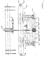
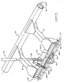
- FIG. 1 illustrates a portion of a spindle type veneer lathe having a frame 10.
- a peel block 12 (which the drawings depict as the minimum diameter core which is left after completion of the veneer peeling operation) is supported between a pair of opposed spindles (not shown) which constitute a “supporting means” for rotatably, drivingly supporting block 12.
- a veneer peeling knife (also not shown but, like the spindles, well known to those skilled in the art) is slidably positionable with respect to rotating block 12 for peeling of veneer therefrom.
- Backup roll support members 14, 16 are rigidly affixed to cylindrical support 18 which is journaled for rotation about first pivot axis 20 by means of supporting bearings 22, 24 which rotatably support the opposed ends of cylinder 18 relative to lathe frame 10.
- First backup roll 26 (which may consist of one or more discrete roller segments 26a, 26b, etc.) is rotatably supported between the ends of support members 14, 16 which together comprise a "first roll support means" for supporting first roll 26 for pivotal positioning thereof about first pivot axis 20 in the manner hereinafter explained.
- Second backup roll 28 (which may also comprise one or more discrete roller segments 28a, 28b, etc.) is journaled for rotation between the ends of a pair of support arms 30, 32 which are in turn pivotally connected to the ends of support arms 14 and 16, respectively.
- Support arms 30, 32 constitute a "second roll support means" for supporting second roll 28 for pivotal positioning thereof about first roll 26 in the manner hereinafter explained. More particularly, support arms 30, 32 are pivotally connected to support arms 14, 16 such that the second roll support means pivots on an axis which coincides with the longitudinal axis of first roll 26.
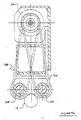
- a "first roll positioning means”, namely, first cylinder 34 is coupled between the lathe frame and support member 36, which is in turn rigidly affixed between the outer ends of support members 14, 16. Controllable actuation of cylinder 34 accordingly causes slidable extension or retraction thereof which in turn causes the first roll support means and, with it, first roll 26 to pivot along a first arc 37 centred on first pivot axis 20.
- a "second roll positioning means”, namely, second hydraulic cylinder 38 is coupled between support member 36 and support member 40, which is in turn rigidly connected between the outer ends of support members 30, 32. Slidable extension or retraction of second cylinder 38 causes the aforementioned second roll support means and, with it, second roll 28, to pivot through a second arc 41 centred on the longitudinal axis of first roll 26.
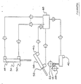
- a knife position sensing means 42 is provided for sensing the position of the knife and for producing a knife position output signal representative thereof.
- First and second control means 44, 46 are respectively provided for controllably actuating first and second cylinders 34, 38 in response to first and second control signals respectively.
- a signal processing means 48 i.e. a suitably programmed microprocessor receives the knife position output signal and produces the first and second control signals in response thereto.
- controllably actuating cylinders 34, 38 in response to changes in the position of the knife, one may produce the second control signal (which controllably actuates second cylinder 38) as a function of the position of first cylinder 34.
- Sensors 50, 52 on cylinders 34, 38 respectively produce signals representative of the position of each cylinder (and therefore representative of the positions of rolls 26, 28 respectively).
- Drive motor 54 is drivingly coupled to first and second rolls 26, 28 by means of drive chains 56, 58 respectively. Accordingly, rolls 26, 28 are both driven at the same speed. However, separate drive motors may if desired be provided for each of the two backup rolls, thereby facilitating controllable actuation of the drive speeds of the two rolls and enabling optimal matching of the roll drive speeds to the rotational speed at different points on the surface of the peel block. Provision of separate drive motors also allows torsional load sharing between the rolls, thereby potentially increasing the total drive torque which may be applied to block 12.
Landscapes
- Engineering & Computer Science (AREA)
- Life Sciences & Earth Sciences (AREA)
- Wood Science & Technology (AREA)
- Forests & Forestry (AREA)
- Manufacturing & Machinery (AREA)
- Mechanical Engineering (AREA)
- Manufacture Of Wood Veneers (AREA)
- Veneer Processing And Manufacture Of Plywood (AREA)
- Debarking, Splitting, And Disintegration Of Timber (AREA)
- Chemical And Physical Treatments For Wood And The Like (AREA)
- Flanged Joints, Insulating Joints, And Other Joints (AREA)
- Structures Of Non-Positive Displacement Pumps (AREA)
- Supporting Of Heads In Record-Carrier Devices (AREA)
Priority Applications (1)
| Application Number | Priority Date | Filing Date | Title |
|---|---|---|---|
| AT88113688T ATE78431T1 (de) | 1987-08-28 | 1988-08-23 | Furnier-rundschaelmaschine mit zwei angetriebenen druckrollen. |
Applications Claiming Priority (2)
| Application Number | Priority Date | Filing Date | Title |
|---|---|---|---|
| CA545656 | 1987-08-28 | ||
| CA000545656A CA1283027C (en) | 1987-08-28 | 1987-08-28 | Veneer lathe with dual powered backup rolls |
Publications (3)
| Publication Number | Publication Date |
|---|---|
| EP0304861A2 true EP0304861A2 (de) | 1989-03-01 |
| EP0304861A3 EP0304861A3 (en) | 1989-07-26 |
| EP0304861B1 EP0304861B1 (de) | 1992-07-22 |
Family
ID=4136358
Family Applications (1)
| Application Number | Title | Priority Date | Filing Date |
|---|---|---|---|
| EP88113688A Expired - Lifetime EP0304861B1 (de) | 1987-08-28 | 1988-08-23 | Furnier-Rundschälmaschine mit zwei angetriebenen Druckrollen |
Country Status (12)
| Country | Link |
|---|---|
| US (1) | US4815508A (de) |
| EP (1) | EP0304861B1 (de) |
| JP (1) | JPH01145102A (de) |
| KR (1) | KR910008249B1 (de) |
| AT (1) | ATE78431T1 (de) |
| AU (1) | AU600163B2 (de) |
| BR (1) | BR8804383A (de) |
| CA (1) | CA1283027C (de) |
| DE (1) | DE3872984T2 (de) |
| ES (1) | ES2034071T3 (de) |
| FI (1) | FI86821C (de) |
| NZ (1) | NZ225845A (de) |
Cited By (1)
| Publication number | Priority date | Publication date | Assignee | Title |
|---|---|---|---|---|
| FR2646627A1 (fr) * | 1989-05-05 | 1990-11-09 | Cremona Angelo & Figlio | Derouleuse de troncs d'arbre avec dispositif antiflexion perfectionne |
Families Citing this family (5)
| Publication number | Priority date | Publication date | Assignee | Title |
|---|---|---|---|---|
| US4922979A (en) * | 1989-06-02 | 1990-05-08 | Premier Gear & Machine Works | Log core steady rest |
| US7370680B2 (en) * | 2006-03-03 | 2008-05-13 | Carlos Alberto Fernando Fezer | Lathe having movable spindles and method |
| RU2480328C2 (ru) * | 2010-12-30 | 2013-04-27 | Общество с ограниченной ответственностью "БЛИЗНЕЦЫ" | Установка для получения из чурака цилиндра максимального объема с механизмом приема, подачи и удаления, механизмом захвата и координации с системой измерения и механизмом обработки с фрезой и муфтой подсоединения ее к приводу, включая монтажную схему установки привода |
| USD700498S1 (en) * | 2013-03-14 | 2014-03-04 | Paul Carter | Woodturning handle |
| CN110757184B (zh) * | 2019-11-03 | 2022-05-17 | 慈利县忠军机电设备制造有限公司 | 一种链式保护带支撑架 |
Citations (2)
| Publication number | Priority date | Publication date | Assignee | Title |
|---|---|---|---|---|
| CA1166045A (en) | 1981-01-12 | 1984-04-24 | Byron B. Brookhyser | Veneer lathe apparatus and method using independently adjustable powered back-up roll |
| CA1202548A (en) | 1982-06-28 | 1986-04-01 | Coe Manufacturing Co. (The) | Veneer lathe drive with powered rolls |
Family Cites Families (6)
| Publication number | Priority date | Publication date | Assignee | Title |
|---|---|---|---|---|
| US3040791A (en) * | 1959-05-29 | 1962-06-26 | Leonard J Fauchon | Log steadying apparatus for veneer lathes |
| GB1548399A (en) * | 1975-09-05 | 1979-07-11 | Lion Match Co Ltd | Veneer-peeling machines |
| SU821148A1 (ru) * | 1979-11-26 | 1981-04-15 | Московский Лесотехнический Институт | Приспособление дл долущивани чура-KOB |
| US4462442A (en) * | 1982-08-30 | 1984-07-31 | Pointner John C | Veneer lathe hold-down rolls |
| US4529021A (en) * | 1984-03-29 | 1985-07-16 | Sun Studs, Inc. | Block stabilizer for veneer lathe and method for operating same |
| IT1188691B (it) * | 1986-05-22 | 1988-01-20 | Lorenzo Cremona | Sfogliatrice rotativa,per la trasformazione di un tronco di legno in fogli,provvista di un dispositivo antiflessione del tronco di tipo perfezionato |
-
1987
- 1987-08-28 CA CA000545656A patent/CA1283027C/en not_active Expired - Lifetime
- 1987-08-31 US US07/091,514 patent/US4815508A/en not_active Expired - Lifetime
-
1988
- 1988-08-16 NZ NZ225845A patent/NZ225845A/xx unknown
- 1988-08-17 FI FI883808A patent/FI86821C/fi not_active IP Right Cessation
- 1988-08-23 ES ES198888113688T patent/ES2034071T3/es not_active Expired - Lifetime
- 1988-08-23 EP EP88113688A patent/EP0304861B1/de not_active Expired - Lifetime
- 1988-08-23 AT AT88113688T patent/ATE78431T1/de not_active IP Right Cessation
- 1988-08-23 AU AU21480/88A patent/AU600163B2/en not_active Ceased
- 1988-08-23 DE DE8888113688T patent/DE3872984T2/de not_active Revoked
- 1988-08-26 BR BR8804383A patent/BR8804383A/pt not_active IP Right Cessation
- 1988-08-27 KR KR1019880010917A patent/KR910008249B1/ko not_active Expired
- 1988-08-29 JP JP63214739A patent/JPH01145102A/ja active Pending
Patent Citations (2)
| Publication number | Priority date | Publication date | Assignee | Title |
|---|---|---|---|---|
| CA1166045A (en) | 1981-01-12 | 1984-04-24 | Byron B. Brookhyser | Veneer lathe apparatus and method using independently adjustable powered back-up roll |
| CA1202548A (en) | 1982-06-28 | 1986-04-01 | Coe Manufacturing Co. (The) | Veneer lathe drive with powered rolls |
Cited By (1)
| Publication number | Priority date | Publication date | Assignee | Title |
|---|---|---|---|---|
| FR2646627A1 (fr) * | 1989-05-05 | 1990-11-09 | Cremona Angelo & Figlio | Derouleuse de troncs d'arbre avec dispositif antiflexion perfectionne |
Also Published As
| Publication number | Publication date |
|---|---|
| FI883808L (fi) | 1989-03-01 |
| FI86821C (fi) | 1992-10-26 |
| ES2034071T3 (es) | 1993-04-01 |
| US4815508A (en) | 1989-03-28 |
| DE3872984T2 (de) | 1993-01-14 |
| EP0304861A3 (en) | 1989-07-26 |
| EP0304861B1 (de) | 1992-07-22 |
| KR890003505A (ko) | 1989-04-15 |
| KR910008249B1 (ko) | 1991-10-12 |
| AU600163B2 (en) | 1990-08-02 |
| FI86821B (fi) | 1992-07-15 |
| BR8804383A (pt) | 1989-03-28 |
| NZ225845A (en) | 1989-10-27 |
| ATE78431T1 (de) | 1992-08-15 |
| CA1283027C (en) | 1991-04-16 |
| AU2148088A (en) | 1989-03-02 |
| DE3872984D1 (de) | 1992-08-27 |
| FI883808A0 (fi) | 1988-08-17 |
| JPH01145102A (ja) | 1989-06-07 |
Similar Documents
| Publication | Publication Date | Title |
|---|---|---|
| EP0304861A2 (de) | Furnier-Rundschälmaschine mit zwei angetriebenen Druckrollen | |
| CA1054493A (en) | Veneer-peeling machines | |
| US5056971A (en) | Operating head chuck unit for automatic machine tools | |
| US4781229A (en) | Spindleless veneer lathe | |
| US4922979A (en) | Log core steady rest | |
| JP4157623B2 (ja) | ベニヤレース | |
| US5018561A (en) | Veneer lathe | |
| JP2000326103A (ja) | 棒材供給機のフィードパイプ | |
| JP3091306B2 (ja) | 回転駆動部チャッキング装置 | |
| JP4094708B2 (ja) | スピンドルレス切削自在なベニヤレースにおける鉋台の後退作動制御方法及びスピンドルレス切削自在なベニヤレース | |
| JPH0657374B2 (ja) | 切削加工装置 | |
| EP0076635A1 (de) | Kurbelzapfenschleifmaschine | |
| JPS6337136Y2 (de) | ||
| JP2515217Y2 (ja) | 偏心加工用割り出し・回転装置 | |
| JP2563025B2 (ja) | 部材の切断制御方法 | |
| JPS6156804A (ja) | フエ−シングユニツト | |
| JPS57173407A (en) | Chucking device | |
| JPS6113287Y2 (de) | ||
| SU1359123A1 (ru) | Окорочный станок | |
| SU663470A1 (ru) | Устройство к токарному станку дл накатывани шлицев | |
| JPS6237683Y2 (de) | ||
| SU1150050A1 (ru) | Станок дл двусторонней бескопирной чистовой обработки лопастей | |
| JPS6029384Y2 (ja) | 工具台 | |
| JPH066243B2 (ja) | 切削加工装置 | |
| JPS5858184B2 (ja) | 工作機械における刃物送り量制御装置 |
Legal Events
| Date | Code | Title | Description |
|---|---|---|---|
| PUAI | Public reference made under article 153(3) epc to a published international application that has entered the european phase |
Free format text: ORIGINAL CODE: 0009012 |
|
| AK | Designated contracting states |
Kind code of ref document: A2 Designated state(s): AT DE ES FR GB IT SE |
|
| PUAL | Search report despatched |
Free format text: ORIGINAL CODE: 0009013 |
|
| AK | Designated contracting states |
Kind code of ref document: A3 Designated state(s): AT DE ES FR GB IT SE |
|
| 17P | Request for examination filed |
Effective date: 19891109 |
|
| 17Q | First examination report despatched |
Effective date: 19910926 |
|
| GRAA | (expected) grant |
Free format text: ORIGINAL CODE: 0009210 |
|
| AK | Designated contracting states |
Kind code of ref document: B1 Designated state(s): AT DE ES FR GB IT SE |
|
| REF | Corresponds to: |
Ref document number: 78431 Country of ref document: AT Date of ref document: 19920815 Kind code of ref document: T |
|
| RIN1 | Information on inventor provided before grant (corrected) |
Inventor name: BUCKSDRUCKER, ARTHUR HORST Inventor name: WILSON, GARY LINDSAY Inventor name: CARTER, PAUL MILTON |
|
| ITF | It: translation for a ep patent filed | ||
| REF | Corresponds to: |
Ref document number: 3872984 Country of ref document: DE Date of ref document: 19920827 |
|
| ET | Fr: translation filed | ||
| REG | Reference to a national code |
Ref country code: ES Ref legal event code: FG2A Ref document number: 2034071 Country of ref document: ES Kind code of ref document: T3 |
|
| PLBI | Opposition filed |
Free format text: ORIGINAL CODE: 0009260 |
|
| 26 | Opposition filed |
Opponent name: COLOMBO & CREMONA S.R.L. Effective date: 19930416 |
|
| PGFP | Annual fee paid to national office [announced via postgrant information from national office to epo] |
Ref country code: AT Payment date: 19930713 Year of fee payment: 6 |
|
| PGFP | Annual fee paid to national office [announced via postgrant information from national office to epo] |
Ref country code: GB Payment date: 19930715 Year of fee payment: 6 |
|
| PGFP | Annual fee paid to national office [announced via postgrant information from national office to epo] |
Ref country code: DE Payment date: 19930721 Year of fee payment: 6 |
|
| PGFP | Annual fee paid to national office [announced via postgrant information from national office to epo] |
Ref country code: ES Payment date: 19930728 Year of fee payment: 6 |
|
| PGFP | Annual fee paid to national office [announced via postgrant information from national office to epo] |
Ref country code: SE Payment date: 19930730 Year of fee payment: 6 |
|
| PGFP | Annual fee paid to national office [announced via postgrant information from national office to epo] |
Ref country code: FR Payment date: 19930827 Year of fee payment: 6 |
|
| PG25 | Lapsed in a contracting state [announced via postgrant information from national office to epo] |
Ref country code: GB Effective date: 19940823 Ref country code: AT Effective date: 19940823 |
|
| PG25 | Lapsed in a contracting state [announced via postgrant information from national office to epo] |
Ref country code: SE Effective date: 19940824 |
|
| EAL | Se: european patent in force in sweden |
Ref document number: 88113688.1 |
|
| GBPC | Gb: european patent ceased through non-payment of renewal fee |
Effective date: 19940823 |
|
| EUG | Se: european patent has lapsed |
Ref document number: 88113688.1 |
|
| RDAG | Patent revoked |
Free format text: ORIGINAL CODE: 0009271 |
|
| STAA | Information on the status of an ep patent application or granted ep patent |
Free format text: STATUS: PATENT REVOKED |
|
| REG | Reference to a national code |
Ref country code: FR Ref legal event code: ST |
|
| 27W | Patent revoked |
Effective date: 19950305 |
|
| PLAB | Opposition data, opponent's data or that of the opponent's representative modified |
Free format text: ORIGINAL CODE: 0009299OPPO |