EP0304815A2 - Circuit de détection et/ou de contrôle de mots de synchronisation contenus dans une transmission en série de données - Google Patents
Circuit de détection et/ou de contrôle de mots de synchronisation contenus dans une transmission en série de données Download PDFInfo
- Publication number
- EP0304815A2 EP0304815A2 EP88113488A EP88113488A EP0304815A2 EP 0304815 A2 EP0304815 A2 EP 0304815A2 EP 88113488 A EP88113488 A EP 88113488A EP 88113488 A EP88113488 A EP 88113488A EP 0304815 A2 EP0304815 A2 EP 0304815A2
- Authority
- EP
- European Patent Office
- Prior art keywords
- shift register
- data stream
- output
- outputs
- detection
- Prior art date
- Legal status (The legal status is an assumption and is not a legal conclusion. Google has not performed a legal analysis and makes no representation as to the accuracy of the status listed.)
- Granted
Links
Images

Classifications
-
- H—ELECTRICITY
- H04—ELECTRIC COMMUNICATION TECHNIQUE
- H04J—MULTIPLEX COMMUNICATION
- H04J3/00—Time-division multiplex systems
- H04J3/02—Details
- H04J3/06—Synchronising arrangements
- H04J3/0602—Systems characterised by the synchronising information used
- H04J3/0605—Special codes used as synchronising signal
Definitions
- the invention relates to a circuit arrangement for recognizing and / or monitoring synchronous words contained in a serial data stream according to the preamble of claim 1.
- the aim is to integrate such circuit arrangements together with others so as to reduce the number of individual parts required, to reduce the installation space and to increase the reliability of the circuit arrangement.
- the size of the chip area on which modules can be integrated is limited. It is therefore important to use the available space particularly sparingly.
- the invention is based on the object, taking into account the chip area which is scarcely dimensioned in the case of highly integrated circuits, to provide a circuit arrangement which, with as little effort as possible, in particular on flip-flop stages, reliably detects and / or monitors synchronous words contained in a serial data stream enables.
- the circuit arrangement according to the invention is limited to the memory cells present in a shift register and only compares the data present in these memory cells. If a data combination currently corresponds to a synchronous word, the logical AND link at the output of the link briefly shows a first detection or monitoring signal. The circuit arrangement is therefore particularly suitable for the first time to find out a combination from a data stream which could correspond to a synchronous word.
- the first check can initially be limited to one part of the synchronous word. To evaluate the remaining digits, the same shift register can then be loaded with a setpoint and the remaining part of the synchronous word, which is now in the other shift register, can then be compared bit by bit with the setpoint. The first shift register is thus used twice, with no delay in the further test due to the loading with the setpoint immediately after the first recognition of part of the synchronous word.
- the receiver for digital satellite broadcasting is intended to receive radio programs in accordance with the specifications of the radio transmission method in TV-SAT.
- the nesting of the programs in a frame structure and the accommodation of additional program information in special service frames and special service superframes are described in more detail in DE-OS 33 08 025.
- each special service frame begins with a 16-digit sync word, followed by data words with program type information about the radio programs broadcast. Of these, however, only the four following data words are assigned useful information, while the data of the remaining two data words are irrelevant.
- the special service superframe SAÜ comprises eight special service frames SA, but the synchronization word for the special service superframe is slightly different from the other synchronous words.
- the first special service frame SA of the special service superframe SAÜ contains program type information for program 1 and program 2.
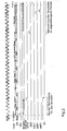
- the circuit shown in FIG. 1 is initially in a search mode after being switched on or after a synchronous failure.
- the data stream that is to say the special service bits, arrive as a KB at a flip-flop 1, which is clocked with a frequency T32N which is of the same frequency as the sequence of the KB.
- the flip-flop 1 is followed by a shift register 2, which in turn is followed by a shift register 3.
- the flip flop 1 and that Shift registers 2 can also be combined as partial shift registers to form a common shift register 1, 2 with a further memory cell, although the first memory cell is only connected upstream and is not loaded with setpoints.
- Inputs of a logic logic element 9 are connected to the outputs Q1 to Q8 of the memory cells of the shift register 2. If a data configuration which corresponds to the synchronous word appears at the outputs Q1 to Q8, a detection and / or monitoring signal SHL occurs at the output of the AND logic element 9. This triggers a counting process in a control circuit 7, 8 in order to be able to query a positive recognition of the synchronous word after the frame duration has expired, and on the other hand calls up a load command LD2, which loads a setpoint into shift register 2, which corresponds to a previous part of the corresponds to the currently recognized sync word. Since the data leaving the shift register 2 are transferred to the shift register 3, parts of longer synchronization words are still available.
- the circuit arrangement is thus able to also be able to check synchronous words which have more than two places in the shift register.
- the output of the shift register 3 and the output of the shift register 2, the latter via a logic circuit 15, are connected to an EXCLUSIVE-OR logic element 16.
- EXCLUSIVE-OR logic element 16 At its output, if the bits of the setpoint and the ACTUAL value stored in shift register 3 match, a logical L appears, and if they do not match, a logical H.
- This signal arrives via a logic element 12, clocked by the clock T32N, into an error counter 4 and from there after a query command SYSU issued by the control circuit 8 in the “search” operating mode and SYLF in the loading drive mode "monitor” in a shift register 5, which holds the successive number of nonexistent or faulty sync words.
- An evaluation matrix 6 connected to an output of the shift register 5 determines when, when detecting or monitoring synchronous words, a switch is made from an “monitoring” operating mode to a “searching” operating mode or when it switches back to the “monitoring” operating mode.
- the shift register 3 is originally used for other purposes, namely for the transmission of data into a connected data processor.
- irrelevant data which does not have to be processed by the connected data processor is transmitted in the data stream according to the above-mentioned specifications before the arrival of the synchronous words. It is therefore possible to interrupt the data transfer to the data processor and instead to enter the full target value of the expected sync word in shift registers 2 and 3 the, the temporally first part being transferred to shift register 3 and the temporally second part being shifted register 2.
- Another problem is the recognition of the synchronous words, which each initiate the special service superframe. These differ from the other synchronous words in that the 11th and 12th digits have a different logical status.
- the incoming synchronizing word is in any case transformed so that it corresponds to the frequently occurring synchronizing word. This means that the frequently occurring synchronous word is not changed and the frequently occurring synchronous word is formed from the rarely occurring synchronous word with the changed 11th and 12th digits. This ensures that the different synchronous words are treated equally and are not displayed as errors.
- the data change circuit used for this purpose comprises two EXCLUSIVE-OR logic elements 17 and 18, the first between the D input and the Q output of flip-flop 1 and the second between the Q output of flip-flop 1 and the Q1 output the flop flop 2 is arranged.
- the outputs of the EXCLUSIVE-OR logic elements 17 and 18 are linked to outputs of the control matrix 8, at which query signals ABF1 and ABF2 are generated at times when the 11th or 12th digit of the synchronous word occurs.
- query signals ABF1 and ABF2 are generated at times when the 11th or 12th digit of the synchronous word occurs.
Landscapes
- Engineering & Computer Science (AREA)
- Computer Networks & Wireless Communication (AREA)
- Signal Processing (AREA)
- Synchronisation In Digital Transmission Systems (AREA)
- Communication Control (AREA)
- Information Transfer Systems (AREA)
- Signal Processing For Digital Recording And Reproducing (AREA)
- Time-Division Multiplex Systems (AREA)
Priority Applications (1)
| Application Number | Priority Date | Filing Date | Title |
|---|---|---|---|
| AT88113488T ATE96592T1 (de) | 1987-08-28 | 1988-08-19 | Schaltungsanordnung zur erkennung und/oder ueberwachung von in einem seriellen datenstrom enthaltenen synchronworten. |
Applications Claiming Priority (2)
| Application Number | Priority Date | Filing Date | Title |
|---|---|---|---|
| DE19873728792 DE3728792A1 (de) | 1987-08-28 | 1987-08-28 | Schaltungsanordnung zur erkennung und/oder ueberwachung von in einem seriellen datenstrom enthaltener synchronworte |
| DE3728792 | 1987-08-28 |
Publications (3)
| Publication Number | Publication Date |
|---|---|
| EP0304815A2 true EP0304815A2 (fr) | 1989-03-01 |
| EP0304815A3 EP0304815A3 (en) | 1990-08-22 |
| EP0304815B1 EP0304815B1 (fr) | 1993-10-27 |
Family
ID=6334722
Family Applications (1)
| Application Number | Title | Priority Date | Filing Date |
|---|---|---|---|
| EP88113488A Expired - Lifetime EP0304815B1 (fr) | 1987-08-28 | 1988-08-19 | Circuit de détection et/ou de contrôle de mots de synchronisation contenus dans une transmission en série de données |
Country Status (6)
| Country | Link |
|---|---|
| EP (1) | EP0304815B1 (fr) |
| JP (1) | JPS6471352A (fr) |
| AT (1) | ATE96592T1 (fr) |
| DE (2) | DE3728792A1 (fr) |
| ES (1) | ES2046260T3 (fr) |
| HK (1) | HK79997A (fr) |
Cited By (1)
| Publication number | Priority date | Publication date | Assignee | Title |
|---|---|---|---|---|
| US5553313A (en) * | 1993-11-10 | 1996-09-03 | Becker Gmbh | Method for detecting information in a RDS data flow |
Families Citing this family (2)
| Publication number | Priority date | Publication date | Assignee | Title |
|---|---|---|---|---|
| DE4304995A1 (de) * | 1993-02-18 | 1994-08-25 | Sel Alcatel Ag | Empfängerschaltung für eine Teilnehmerstation eines Netzwerks |
| DE4338422C1 (de) * | 1993-11-10 | 1995-02-09 | Becker Gmbh | Verfahren zur Synchronisation eines RDS-Decoders |
Citations (1)
| Publication number | Priority date | Publication date | Assignee | Title |
|---|---|---|---|---|
| US4607378A (en) * | 1984-10-22 | 1986-08-19 | Honeywell Inc. | Detector for detecting sync bits in a stream of data bits |
Family Cites Families (5)
| Publication number | Priority date | Publication date | Assignee | Title |
|---|---|---|---|---|
| JPS55135450A (en) * | 1979-04-10 | 1980-10-22 | Mitsubishi Electric Corp | Synchronous signal formation for digital transmission signal |
| DE2920809A1 (de) * | 1979-05-22 | 1980-11-27 | Siemens Ag | Verfahren und schaltungsanordnung zur synchronisierung bei der uebertragung von digitalen nachrichtensignalen |
| DE3103574C2 (de) * | 1981-02-03 | 1983-06-16 | Siemens AG, 1000 Berlin und 8000 München | Schaltungsanordnung zum Herstellen und Aufrechterhalten des Gleichlaufs zwischen von örtlich erzeugten Bittaktimpulsen abgeleiteten Envelopetaktimpulsen und in Envelopes eines binärcodierten Signals enthaltenen Synchronisierbits |
| DE3132198C2 (de) * | 1981-08-14 | 1984-02-02 | Felten & Guilleaume Fernmeldeanlagen GmbH, 8500 Nürnberg | Schaltungsanordnung zum Erkennen der Synchronisierbitstelle in einem Digitalsignal |
| JPS59221047A (ja) * | 1983-05-30 | 1984-12-12 | Victor Co Of Japan Ltd | デイジタル信号伝送における同期信号検出回路 |
-
1987
- 1987-08-28 DE DE19873728792 patent/DE3728792A1/de not_active Withdrawn
-
1988
- 1988-08-19 ES ES198888113488T patent/ES2046260T3/es not_active Expired - Lifetime
- 1988-08-19 EP EP88113488A patent/EP0304815B1/fr not_active Expired - Lifetime
- 1988-08-19 AT AT88113488T patent/ATE96592T1/de not_active IP Right Cessation
- 1988-08-19 DE DE88113488T patent/DE3885206D1/de not_active Expired - Fee Related
- 1988-08-29 JP JP63212659A patent/JPS6471352A/ja active Pending
-
1997
- 1997-06-12 HK HK79997A patent/HK79997A/xx not_active IP Right Cessation
Patent Citations (1)
| Publication number | Priority date | Publication date | Assignee | Title |
|---|---|---|---|---|
| US4607378A (en) * | 1984-10-22 | 1986-08-19 | Honeywell Inc. | Detector for detecting sync bits in a stream of data bits |
Cited By (1)
| Publication number | Priority date | Publication date | Assignee | Title |
|---|---|---|---|---|
| US5553313A (en) * | 1993-11-10 | 1996-09-03 | Becker Gmbh | Method for detecting information in a RDS data flow |
Also Published As
| Publication number | Publication date |
|---|---|
| JPS6471352A (en) | 1989-03-16 |
| EP0304815B1 (fr) | 1993-10-27 |
| DE3728792A1 (de) | 1989-03-09 |
| HK79997A (en) | 1997-06-20 |
| EP0304815A3 (en) | 1990-08-22 |
| ATE96592T1 (de) | 1993-11-15 |
| DE3885206D1 (de) | 1993-12-02 |
| ES2046260T3 (es) | 1994-02-01 |
Similar Documents
| Publication | Publication Date | Title |
|---|---|---|
| DE3443925C1 (de) | Schaltungsanordnung zum Unterscheiden der beiden Halbbilder in einem Fernsehsignal | |
| DE2721319A1 (de) | Einrichtung zur selbsttaetigen aenderung der prozessor/speicher-konfiguration | |
| DE4432061C1 (de) | Paketübertragungssystem | |
| DE2621882B2 (de) | Speicher für Rechenautomaten mit mindestens zwei parallel angeordneten, einen Rücklaufkreis aufweisenden Speicherschleifen | |
| DE2121330C3 (de) | Verfahren und Schaltungsanordnung zum Prüfen digital arbeitender elektronischer Geräte und ihrer Bauteile | |
| DE1424741A1 (de) | Einrichtung zum Durchsuchen eines Speichers | |
| DE2729362C2 (de) | Digitale Datenverarbeitungsanordnung, insbesondere für die Eisenbahnsicherungstechnik, mit in zwei Kanälen dieselben Informationen verarbeitenden Schaltwerken | |
| EP0226241A2 (fr) | Circuit d'évaluation de données pour un système de programmation vidéo dans un enregistreur à bande vidéo | |
| DE2641700C2 (fr) | ||
| EP0304815B1 (fr) | Circuit de détection et/ou de contrôle de mots de synchronisation contenus dans une transmission en série de données | |
| EP0333273A2 (fr) | Générateur de signal de commande pour le traitement d'un signal vidéo | |
| DE2854655A1 (de) | Signaluebertragungs-steueranordnung | |
| EP0195421B1 (fr) | Procédé et arrangement pour la synchronisation de signaux numériques d'informations | |
| EP0204376B1 (fr) | Circuit pour l'exploration d'un signal ternaire | |
| DE2524129C3 (de) | Zeitsteuereinheit für die Steuerung logischer Schaltungen | |
| DE3132198C2 (de) | Schaltungsanordnung zum Erkennen der Synchronisierbitstelle in einem Digitalsignal | |
| DE4422784C2 (de) | Schaltungsanordnung mit wenigstens einer Schaltungseinheit wie einem Register, einer Speicherzelle, einer Speicheranordnung oder dergleichen | |
| DE3315683C1 (de) | Schaltungsanordnung zum Abfragen einer Matrix aus Tastenkontakten | |
| DE3034754C2 (de) | Schaltungsanordnung zur Erzeugung von Adreßsignalen | |
| EP0304814B1 (fr) | Dispositif de synchronisation | |
| CH625067A5 (en) | Device for error processing in a microprogram-controlled data processing system. | |
| EP0110257B1 (fr) | Circuit pour adresser des dispositifs | |
| DE2824862A1 (de) | Monolithisch integrierte digitale halbleiterschaltung | |
| DE2130917C3 (de) | Schaltungsanordnung von Impulszählern zum Prüfen eines Eingabe-Musgabe-Steuerwerks in einem Rechner-Steuersystem | |
| EP0840204A2 (fr) | Circuit électrique pour l'évaluation sérielle d'une séquence de bits |
Legal Events
| Date | Code | Title | Description |
|---|---|---|---|
| PUAI | Public reference made under article 153(3) epc to a published international application that has entered the european phase |
Free format text: ORIGINAL CODE: 0009012 |
|
| AK | Designated contracting states |
Kind code of ref document: A2 Designated state(s): AT BE CH DE ES FR GB GR IT LI LU NL SE |
|
| PUAL | Search report despatched |
Free format text: ORIGINAL CODE: 0009013 |
|
| AK | Designated contracting states |
Kind code of ref document: A3 Designated state(s): AT BE CH DE ES FR GB GR IT LI LU NL SE |
|
| 17P | Request for examination filed |
Effective date: 19901231 |
|
| 17Q | First examination report despatched |
Effective date: 19920904 |
|
| RAP1 | Party data changed (applicant data changed or rights of an application transferred) |
Owner name: TELEFUNKEN FERNSEH UND RUNDFUNK GMBH |
|
| GRAA | (expected) grant |
Free format text: ORIGINAL CODE: 0009210 |
|
| AK | Designated contracting states |
Kind code of ref document: B1 Designated state(s): AT BE CH DE ES FR GB GR IT LI LU NL SE |
|
| PG25 | Lapsed in a contracting state [announced via postgrant information from national office to epo] |
Ref country code: SE Effective date: 19931027 Ref country code: GR Free format text: LAPSE BECAUSE OF FAILURE TO SUBMIT A TRANSLATION OF THE DESCRIPTION OR TO PAY THE FEE WITHIN THE PRESCRIBED TIME-LIMIT Effective date: 19931027 |
|
| REF | Corresponds to: |
Ref document number: 96592 Country of ref document: AT Date of ref document: 19931115 Kind code of ref document: T |
|
| ITF | It: translation for a ep patent filed |
Owner name: BARZANO' E ZANARDO MILA |
|
| REF | Corresponds to: |
Ref document number: 3885206 Country of ref document: DE Date of ref document: 19931202 |
|
| GBT | Gb: translation of ep patent filed (gb section 77(6)(a)/1977) |
Effective date: 19931109 |
|
| ET | Fr: translation filed | ||
| PLBE | No opposition filed within time limit |
Free format text: ORIGINAL CODE: 0009261 |
|
| STAA | Information on the status of an ep patent application or granted ep patent |
Free format text: STATUS: NO OPPOSITION FILED WITHIN TIME LIMIT |
|
| PG25 | Lapsed in a contracting state [announced via postgrant information from national office to epo] |
Ref country code: LU Free format text: LAPSE BECAUSE OF NON-PAYMENT OF DUE FEES Effective date: 19940831 |
|
| 26N | No opposition filed | ||
| REG | Reference to a national code |
Ref country code: CH Ref legal event code: PFA Free format text: THOMSON CONSUMER ELECTRONIC SALES GMBH |
|
| NLT1 | Nl: modifications of names registered in virtue of documents presented to the patent office pursuant to art. 16 a, paragraph 1 |
Owner name: THOMSON CONSUMER ELECTRONICS SALES GMBH TE HANNOVE |
|
| REG | Reference to a national code |
Ref country code: ES Ref legal event code: PC2A Owner name: THOMSON CONSUMER ELECTRONICS SALES GMBH |
|
| PGFP | Annual fee paid to national office [announced via postgrant information from national office to epo] |
Ref country code: GB Payment date: 19980703 Year of fee payment: 11 |
|
| PGFP | Annual fee paid to national office [announced via postgrant information from national office to epo] |
Ref country code: FR Payment date: 19980814 Year of fee payment: 11 |
|
| PGFP | Annual fee paid to national office [announced via postgrant information from national office to epo] |
Ref country code: BE Payment date: 19980824 Year of fee payment: 11 |
|
| PGFP | Annual fee paid to national office [announced via postgrant information from national office to epo] |
Ref country code: AT Payment date: 19980825 Year of fee payment: 11 |
|
| PGFP | Annual fee paid to national office [announced via postgrant information from national office to epo] |
Ref country code: CH Payment date: 19980826 Year of fee payment: 11 |
|
| PGFP | Annual fee paid to national office [announced via postgrant information from national office to epo] |
Ref country code: NL Payment date: 19980827 Year of fee payment: 11 |
|
| PGFP | Annual fee paid to national office [announced via postgrant information from national office to epo] |
Ref country code: ES Payment date: 19980828 Year of fee payment: 11 |
|
| PG25 | Lapsed in a contracting state [announced via postgrant information from national office to epo] |
Ref country code: GB Free format text: LAPSE BECAUSE OF NON-PAYMENT OF DUE FEES Effective date: 19990819 Ref country code: AT Free format text: LAPSE BECAUSE OF NON-PAYMENT OF DUE FEES Effective date: 19990819 |
|
| PG25 | Lapsed in a contracting state [announced via postgrant information from national office to epo] |
Ref country code: ES Free format text: LAPSE BECAUSE OF NON-PAYMENT OF DUE FEES Effective date: 19990820 |
|
| PG25 | Lapsed in a contracting state [announced via postgrant information from national office to epo] |
Ref country code: LI Free format text: LAPSE BECAUSE OF NON-PAYMENT OF DUE FEES Effective date: 19990831 Ref country code: CH Free format text: LAPSE BECAUSE OF NON-PAYMENT OF DUE FEES Effective date: 19990831 Ref country code: BE Free format text: LAPSE BECAUSE OF NON-PAYMENT OF DUE FEES Effective date: 19990831 |
|
| BERE | Be: lapsed |
Owner name: THOMSON CONSUMER ELECTRONICS SALES G.M.B.H. Effective date: 19990831 |
|
| PG25 | Lapsed in a contracting state [announced via postgrant information from national office to epo] |
Ref country code: NL Free format text: LAPSE BECAUSE OF NON-PAYMENT OF DUE FEES Effective date: 20000301 |
|
| GBPC | Gb: european patent ceased through non-payment of renewal fee |
Effective date: 19990819 |
|
| REG | Reference to a national code |
Ref country code: CH Ref legal event code: PL |
|
| PG25 | Lapsed in a contracting state [announced via postgrant information from national office to epo] |
Ref country code: FR Free format text: LAPSE BECAUSE OF NON-PAYMENT OF DUE FEES Effective date: 20000428 |
|
| NLV4 | Nl: lapsed or anulled due to non-payment of the annual fee |
Effective date: 20000301 |
|
| REG | Reference to a national code |
Ref country code: FR Ref legal event code: ST |
|
| PGFP | Annual fee paid to national office [announced via postgrant information from national office to epo] |
Ref country code: DE Payment date: 20010111 Year of fee payment: 13 |
|
| PG25 | Lapsed in a contracting state [announced via postgrant information from national office to epo] |
Ref country code: DE Free format text: LAPSE BECAUSE OF NON-PAYMENT OF DUE FEES Effective date: 20020501 |
|
| REG | Reference to a national code |
Ref country code: ES Ref legal event code: FD2A Effective date: 20000911 |
|
| PG25 | Lapsed in a contracting state [announced via postgrant information from national office to epo] |
Ref country code: IT Free format text: LAPSE BECAUSE OF NON-PAYMENT OF DUE FEES;WARNING: LAPSES OF ITALIAN PATENTS WITH EFFECTIVE DATE BEFORE 2007 MAY HAVE OCCURRED AT ANY TIME BEFORE 2007. THE CORRECT EFFECTIVE DATE MAY BE DIFFERENT FROM THE ONE RECORDED. Effective date: 20050819 |