EP0304531A1 - Schliessblech - Google Patents
Schliessblech Download PDFInfo
- Publication number
- EP0304531A1 EP0304531A1 EP87810484A EP87810484A EP0304531A1 EP 0304531 A1 EP0304531 A1 EP 0304531A1 EP 87810484 A EP87810484 A EP 87810484A EP 87810484 A EP87810484 A EP 87810484A EP 0304531 A1 EP0304531 A1 EP 0304531A1
- Authority
- EP
- European Patent Office
- Prior art keywords
- piece
- lock
- striking plate
- receiving
- flat part
- Prior art date
- Legal status (The legal status is an assumption and is not a legal conclusion. Google has not performed a legal analysis and makes no representation as to the accuracy of the status listed.)
- Granted
Links
- 239000002023 wood Substances 0.000 description 6
- 229920002522 Wood fibre Polymers 0.000 description 1
- 238000004873 anchoring Methods 0.000 description 1
- 238000010276 construction Methods 0.000 description 1
- 230000007547 defect Effects 0.000 description 1
- 238000009434 installation Methods 0.000 description 1
- 238000003801 milling Methods 0.000 description 1
- 239000002025 wood fiber Substances 0.000 description 1
Images
Classifications
-
- E—FIXED CONSTRUCTIONS
- E05—LOCKS; KEYS; WINDOW OR DOOR FITTINGS; SAFES
- E05B—LOCKS; ACCESSORIES THEREFOR; HANDCUFFS
- E05B15/00—Other details of locks; Parts for engagement by bolts of fastening devices
- E05B15/02—Striking-plates; Keepers; Bolt staples; Escutcheons
- E05B15/0205—Striking-plates, keepers, staples
-
- E—FIXED CONSTRUCTIONS
- E05—LOCKS; KEYS; WINDOW OR DOOR FITTINGS; SAFES
- E05B—LOCKS; ACCESSORIES THEREFOR; HANDCUFFS
- E05B63/00—Locks or fastenings with special structural characteristics
- E05B63/04—Locks or fastenings with special structural characteristics for alternative use on the right-hand or left-hand side of wings
Definitions
- the present invention relates to a striking plate for receiving locking parts of a lock for doors or windows, which can be fastened in a wooden frame by means of fastening screws.
- striking plates for front doors and apartment doors are also considered, in which attempts are always made to increase security, i.e. their tear resistance.
- a large number of striking plates are known which attempt to meet the higher security requirements. For example, there are also those in which a part of the U-shaped or angularly curved striking plate is anchored in a groove in the door frame, which striking plates, like others, can have support bolts or the like. Such striking plates have the disadvantage, among other things, that installation is relatively complex and special milling cutters are required. With most striking plates, the fastening screws are inserted into the wood of the frame parallel to the slide bolt or latch of the lock, with the risk that the pull-out strength will be reduced if the wood fibers run unfavorably.
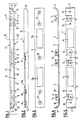
- the striking plate according to the invention consists of two pieces, the first piece 1 according to FIGS. 4 + 5 and the second piece 2 according to FIGS. 2 + 3.
- the first piece 1 is essentially flat and has two transverse sides 3 curved in the direction of the lock, whereby this whole first piece 1 is embedded in the wooden frame 4 of a door, as can be seen from FIG. From the flat part 5 of the first piece 1 project - in the present example four - tabs 6 with holes 7 for receiving fastening screws 8, see Figure 1, these tabs forming an angle of approximately 35 ° with respect to the flat part 5.
- This piece of striking plate also has openings 9 for receiving the slide bolt 16 of the lock, if it is pushed out twice as shown in dot-dash lines in FIG. 7.
- the slide bolt is only guided through one opening 9 and a corresponding recess is made in frame 4.
- the flat part 5 of the first piece has a number of holes 10 for receiving other fastening screws 11, which pass through both the second piece 2 and the first piece 1.
- the second piece 2 is U-shaped, the height of the longitudinal legs 12 being approximately equal to the height of the transverse sides 3 of the first piece, so that a box closed on all sides results in the installed state according to FIG .
- the rounded portions 13 on the longitudinal legs correspond to the rounded portions of the transverse sides 3.
- the piece 2 also has two identical and symmetrically arranged openings 9a for the latch and the slide bolt.
- this second piece has 2 bores 14, which coincide with the bores 10 on the first piece and serve to hold the fastening screws, which are designed as countersunk screws 11.
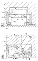
- a recess 15 corresponding to piece 1 is first milled out of the frame 4 using a router, it being emphasized that such a router is one of the simplest tools and this recess 15 can be produced very easily and quickly. Then the first piece 1 is fastened to the tab 6 by means of fastening screws 8, whereupon the second piece 2 is placed on and fastened with the countersunk screws 11 on the piece 1 and in the wood of the frame 4.
- a router is one of the simplest tools and this recess 15 can be produced very easily and quickly.
- the striking plate overall has a flat construction and is symmetrical in the embodiment according to the present drawing, so that it can be used both on the left and on the right. Tests have shown that defects only occur above a pull-out force of more than 10,000 N, while this threshold for normal, conventional striking plates is in the range from 2000 to 5000 N, with the wood generally tearing out, while in tests with the striking plate according to the invention this sheet itself was broken without the wood tearing out.
- the high pull-out strength is achieved not least by the fact that, when the pull-out force F acts on the upper, second piece (2), the latter against the edges 6b of the ends 6a of the tabs located near the leg 12a 6 is pressed, which distributes this force to both anchored pieces.
- the ends 6a are angled to run parallel to the flat part 5.
- the striking plate according to the invention not only offers high security but also solves an as yet unresolved aesthetic problem for security striking plates in that it can be installed in such a way that it is no longer visible when the door is closed.
- such a striking plate is intended for house and apartment end doors, but it is also possible to use such two-part striking plates for locks with multiple slide bolts and as striking plates for windows.
Landscapes
- Securing Of Glass Panes Or The Like (AREA)
- Door And Window Frames Mounted To Openings (AREA)
- Supports Or Holders For Household Use (AREA)
- Push-Button Switches (AREA)
Abstract
Description
- Die vorliegende Erfindung bezieht sich auf ein Schliessblech zur Aufnahme von Schliessteilen eines Verschlusses für Türen oder Fenster, das mittels Befestigungsschrauben in einem Holzrahmen befestigbar ist. Dabei ist insbesondere auch an Schliessbleche für Haustüren und Wohnungsabschlusstüren gedacht, bei denen stets versucht wird, die Sicherheit zu erhöhen, d.h. deren Ausreissfestigkeit.
- Es sind eine Vielzahl von Schliessblechen bekannt, die versuchen, den höheren Sicherheitsanforderungen Genüge zu leisten. So gibt es beispielsweise auch solche, bei denen ein Teil des U- oder winkelförmig gebogenen Schliessbleches in eine Nut des Türrahmens verankert wird, wobei diese Schliessbleche, wie andere auch, Stützbolzen oder dergleichen aufweisen können. Solche Schliessbleche haben unter anderem den Nachteil, dass der Einbau relativ aufwendig wird und spezielle Fräser dazu benötigt werden. Bei den meisten Schliessblechen werden die Befestigungsschrauben parallel zum Schubriegel, bzw. Falle des Schlosses in das Holz des Rahmens eingebracht, wobei die Gefahr besteht, dass die Ausreissfestigkeit bei ungünstigem Verlauf der Holzfasern herabgesetzt wird.
- Es ist von obigem ausgehend Aufgabe der vorliegenden Erfindung ein Schliessblech anzugeben, das einerseits leicht montiert werden kann und andererseits eine hohe Ausreissfestigkeit besitzt. Ein solches Schliessblech wird in den Ansprüchen beschrieben.
- Die Erfindung wird im folgenden anhand einer Zeichnung eines Ausführungsbeispiels näher erläutert.
- Fig. 1 zeigt in Seitenansicht ein montiertes, erfin dungsgemässes Schliessblech,
- Fig. 2 zeigt, teilweise längsgeschnitten, ein Stück des Schliessbleches gemäss Figur 1,
- Fig. 3 zeigt das Stück von Figur 2 von oben,
- Fig. 4 zeigt, teilweise längsgeschnitten, das zweite Stück des Schliessbleches,
- Fig. 5 zeigt das zweite Stück gemäss Figur 4 von oben,
- Fig. 6 zeigt, im vergrösserten Massstab, einen Schnitt gemäss der Linie VI/VI von Figur 1, und
- Fig. 7 zeigt einen Schnitt gemäss der Linie VII/VII der Figur 1 im vergrösserten Massstab.
- Das erfindungsgemässe Schliessblech besteht aus zwei Stücken, dem ersten Stück 1 gemäss Figuren 4 + 5 und dem zweiten Stück 2 gemäss Figuren 2 + 3. Das erste Stück 1 ist im wesentlichen eben ausgebildet und weist zwei in Richtung des Schlosses gebogene Querseiten 3 auf, wobei dieses ganze erste Stück 1 im Holzrahmen 4 einer Türe eingelassen ist, wie dies aus Figur 1 hervorgeht. Aus dem ebenen Teil 5 des ersten Stückes 1 ragen - in vorliegendem Beispiel vier - Lappen 6 mit Bohrungen 7 zur Aufnahme von Befestigungsschrauben 8, siehe Figur 1, heraus, wobei diese Lappen etwa einen Winkel von 35° bezüglich des ebenen Teils 5 bilden. Dieses Schliessblechstück weist ferner Oeffnungen 9 zur Aufnahme des Schubriegels 16 des Schlosses auf, falls dieser wie in Figur 7 strichpunktiert eingezeichnet, doppelt herausgeschoben wird. Da die beiden Stücke 1 und 2 symmetrisch ausgeführt sind, wird der Schubriegel jeweils nur durch eine Oeffnung 9 geführt und im Rahmen 4 eine entsprechende Ausnehmung angefertigt. Neben den Lappen 6 mit den Bohrungen 7 besitzt das ebene Teil 5 des ersten Stücks eine Anzahl Bohrungen 10 zur Aufnahme von anderen Befestigungsschrauben 11, die sowohl durch das zweite Stück 2 als auch durch das erste Stück 1 hindurchgehen.
- Das zweite Stück 2 ist, wie insbesondere aus Figur 2 hervorgeht, U-förmig ausgebildet, wobei die Höhe der Längsschenkel 12 etwa gleich der Höhe der Querseiten 3 des ersten Stücks ist, so dass im eingebauten Zustand gemäss Figur 1 sich ein allseitig geschlossener Kasten ergibt. Selbstverständlich entsprechen dabei die Abrundungen 13 an den Längsschenkeln den Rundungen der Querseiten 3. Das Stück 2 weist ebenfalls zwei gleiche und symmetrisch angeordnete Oeffnungen 9a für die Falle und den Schubriegel auf. Ausserdem besitzt dieses zweite Stück 2 Bohrungen 14, die sich mit den Bohrungen 10 am ersten Stück decken und der Aufnahme der Befestigungsschrauben, die als Senkkopfschrauben 11 ausgebildet sind, dienen.
- Zur Befestigung dieses zweiteiligen Schliessbleches wird zuerst mit einer Oberfräse eine dem Stück 1 entsprechende Ausnehmung 15 aus dem Rahmen 4 herausgefräst, wobei hervorzuheben ist, dass eine solche Oberfräse zu den einfachsten Werkzeugen zählt und diese Ausnehmung 15 sehr einfach und schnell hergestellt werden kann. Anschliessend wird das erste Stück 1 mittels Befestigungsschrauben 8 an den Lappen 6 befestigt, woraufhin das zweite Stück 2 aufgesetzt und mit den Senkkopfschrauben 11 auf dem Stück 1 und im Holz des Rahmens 4 befestigt wird. Insbesondere aus der Ausschnittsvergrösserung gemäss Figur 6 geht hervor, dass die Befestigung des ersten Stückes mittels schräg in das Holz hineinreichender Schrauben 8 sowie die Befestigung des zweiten Stückes mittels Schrauben 11, die etwa parallel zum Schubriegel 16 oder zu der Falle verlaufen, eine äusserst starke Verankerung mit hoher Ausreissfestigkeit ergibt, da die Ausreisskraft auf eine grosse Anzahl von Befestigungsschrauben wirkt, die in zwei verschiedenen Richtungen im Holz verankert sind.
- Aus Figur 1 ergibt sich ferner, dass das Schliessblech insgesamt eine flache Konstruktion ergibt und bei der Ausführung gemäss der vorliegenden Zeichnung symmetrisch ist, so dass es sowohl links als auch rechts verwendbar ist. Versuche haben ergeben, dass Defekte erst oberhalb einer Ausreisskraft von über 10'000 N erfolgen, während diese Schwelle bei normalen, herkömmlichen Schliessblechen im Bereich von 2000 - 5000 N liegen, wobei in der Regel das Holz ausreisst, während bei Versuchen mit dem erfindungsgemässen Schliessblech dieses Blech selber defekt wurde, ohne dass das Holz ausriss.
- Aus den Figuren 6 und 7 geht hervor, dass die hohe Ausreissfestigkeit nicht zuletzt dadurch erzielt wird, dass beim Einwirken der Ausreisskraft F auf das obere, zweite Stück (2) dieses gegen die nahe dem Schenkel 12a sich befindlichen Kanten 6b der Enden 6a der Lappen 6 gedrückt wird, womit sich diese Kraft auf beide verankerten Stücke verteilt. Die Enden 6a sind abgewinkelt, um parallel zum ebenen Teil 5 zu verlaufen.
- Das erfindungsgemässe Schliessblech bietet nicht nur hohe Sicherheit sondern löst auch ein bis anhin nicht bewältigtes ästhetisches Problem für Sicherheitsschliessbleche, indem es so eingebaut werden kann, dass es bei geschlossener Türe nicht mehr sichtbar ist.
- In der Mehrzahl von Fällen ist ein solches Schliessblech für Haus- und Wohnungsabschlusstüren gedacht, doch ist es auch möglich, solche zweiteilige Schliessbleche für Schlösser mit mehreren Schubriegeln sowie als Schliessplatten für Fenster zu verwenden.
Claims (3)
Priority Applications (3)
| Application Number | Priority Date | Filing Date | Title |
|---|---|---|---|
| DE8787810484T DE3765640D1 (de) | 1987-08-27 | 1987-08-27 | Schliessblech. |
| AT87810484T ATE57565T1 (de) | 1987-08-27 | 1987-08-27 | Schliessblech. |
| EP87810484A EP0304531B1 (de) | 1987-08-27 | 1987-08-27 | Schliessblech |
Applications Claiming Priority (1)
| Application Number | Priority Date | Filing Date | Title |
|---|---|---|---|
| EP87810484A EP0304531B1 (de) | 1987-08-27 | 1987-08-27 | Schliessblech |
Publications (2)
| Publication Number | Publication Date |
|---|---|
| EP0304531A1 true EP0304531A1 (de) | 1989-03-01 |
| EP0304531B1 EP0304531B1 (de) | 1990-10-17 |
Family
ID=8198414
Family Applications (1)
| Application Number | Title | Priority Date | Filing Date |
|---|---|---|---|
| EP87810484A Expired - Lifetime EP0304531B1 (de) | 1987-08-27 | 1987-08-27 | Schliessblech |
Country Status (3)
| Country | Link |
|---|---|
| EP (1) | EP0304531B1 (de) |
| AT (1) | ATE57565T1 (de) |
| DE (1) | DE3765640D1 (de) |
Cited By (4)
| Publication number | Priority date | Publication date | Assignee | Title |
|---|---|---|---|---|
| DE29810360U1 (de) * | 1998-06-09 | 1998-08-27 | RW Rüdel Werner Patentverwertung Entwicklung u. Konstruktion, 84307 Eggenfelden | Schließblech für Türzargen bzw. integrale Türzarge mit einem Schließbereich |
| EP0964118A1 (de) * | 1998-05-30 | 1999-12-15 | Ernst Straub GmbH, Baubeschläge und Werkzeuge | Schliessblechanordnung |
| RU2171880C1 (ru) * | 2000-01-26 | 2001-08-10 | Открытое акционерное общество "Пластик" | Декоративная накладка |
| BE1019537A5 (nl) * | 2010-10-13 | 2012-08-07 | Thery Marc Willy Christianne | Samenstel van een sluitplaat en een sluitkom. |
Citations (2)
| Publication number | Priority date | Publication date | Assignee | Title |
|---|---|---|---|---|
| US1365156A (en) * | 1920-02-24 | 1921-01-11 | Yale & Towne Mfg Co | Keeper for night-latches |
| CH365630A (fr) * | 1961-02-21 | 1962-11-15 | Oswald Walter | Gâche pour serrure de porte |
-
1987
- 1987-08-27 EP EP87810484A patent/EP0304531B1/de not_active Expired - Lifetime
- 1987-08-27 AT AT87810484T patent/ATE57565T1/de not_active IP Right Cessation
- 1987-08-27 DE DE8787810484T patent/DE3765640D1/de not_active Expired - Fee Related
Patent Citations (2)
| Publication number | Priority date | Publication date | Assignee | Title |
|---|---|---|---|---|
| US1365156A (en) * | 1920-02-24 | 1921-01-11 | Yale & Towne Mfg Co | Keeper for night-latches |
| CH365630A (fr) * | 1961-02-21 | 1962-11-15 | Oswald Walter | Gâche pour serrure de porte |
Cited By (4)
| Publication number | Priority date | Publication date | Assignee | Title |
|---|---|---|---|---|
| EP0964118A1 (de) * | 1998-05-30 | 1999-12-15 | Ernst Straub GmbH, Baubeschläge und Werkzeuge | Schliessblechanordnung |
| DE29810360U1 (de) * | 1998-06-09 | 1998-08-27 | RW Rüdel Werner Patentverwertung Entwicklung u. Konstruktion, 84307 Eggenfelden | Schließblech für Türzargen bzw. integrale Türzarge mit einem Schließbereich |
| RU2171880C1 (ru) * | 2000-01-26 | 2001-08-10 | Открытое акционерное общество "Пластик" | Декоративная накладка |
| BE1019537A5 (nl) * | 2010-10-13 | 2012-08-07 | Thery Marc Willy Christianne | Samenstel van een sluitplaat en een sluitkom. |
Also Published As
| Publication number | Publication date |
|---|---|
| ATE57565T1 (de) | 1990-11-15 |
| DE3765640D1 (de) | 1990-11-22 |
| EP0304531B1 (de) | 1990-10-17 |
Similar Documents
| Publication | Publication Date | Title |
|---|---|---|
| WO2004106679A1 (de) | Schiebetür | |
| EP0304531B1 (de) | Schliessblech | |
| EP0761920B1 (de) | Fenster/Tür mit Dreh-Kipp-Beschlag | |
| CH656175A5 (de) | Schliessstueck zur aufnahme des freien endes eines sperrorgans. | |
| EP0733761B1 (de) | Flügelrahmen | |
| EP0807731A2 (de) | Durchgehende Schliessleiste für Türen | |
| DE2946933A1 (de) | Sicherheitsschliessblech | |
| DE29600891U1 (de) | Sicherungseinrichtung | |
| DE19502362C2 (de) | Positionierungseinrichtung für Beschlagteile | |
| DE69705077T2 (de) | Scharnier | |
| DE9015120U1 (de) | Schließblech | |
| EP0118113A2 (de) | Kastenschloss mit Sperrbügel | |
| CH664418A5 (en) | Double-leaf burglar-resistant door - has bar on channel-section rail on stationary leaf covering join with hinging one | |
| DE29806594U1 (de) | Gegen Einbruch hohen Widerstand leistendes Scharnier | |
| DE102023113130A1 (de) | Türstopper und System aus Tür und Türstopper | |
| DE19646585C2 (de) | Ortsveränderliche Tür | |
| CH683789A5 (de) | Scharnier. | |
| EP0331979A1 (de) | Schliessblech für Türverschlüsse | |
| DE2553607A1 (de) | Holztuerstock mit einem schliessblech | |
| DE9208758U1 (de) | Vorrichtung zur Erhöhung der Sicherheit von Türen, Fenstern o.dgl. gegen Einbruch | |
| DE8812938U1 (de) | Beschlag zur Sicherung von beweglichen Flügeln für Fenster, Türen o.dgl. gegen Aufhebeln von außen | |
| DE7823228U1 (de) | Tuerbeschlag | |
| DE3825645A1 (de) | Schliessfachtuere mit einem tuerblatt und einem in einem schlosskasten angeordneten riegelschloss | |
| DE2755961A1 (de) | Halterung von mit stulpschienen ausgestatteten schloessern | |
| EP0736662A1 (de) | Gehtüren in grossen Toren |
Legal Events
| Date | Code | Title | Description |
|---|---|---|---|
| PUAI | Public reference made under article 153(3) epc to a published international application that has entered the european phase |
Free format text: ORIGINAL CODE: 0009012 |
|
| AK | Designated contracting states |
Kind code of ref document: A1 Designated state(s): AT BE CH DE ES FR GB GR IT LI LU NL SE |
|
| RBV | Designated contracting states (corrected) |
Designated state(s): AT BE CH DE FR IT LI NL SE |
|
| 17P | Request for examination filed |
Effective date: 19890510 |
|
| 17Q | First examination report despatched |
Effective date: 19891228 |
|
| GRAA | (expected) grant |
Free format text: ORIGINAL CODE: 0009210 |
|
| ITF | It: translation for a ep patent filed | ||
| AK | Designated contracting states |
Kind code of ref document: B1 Designated state(s): AT BE CH DE FR IT LI NL SE |
|
| REF | Corresponds to: |
Ref document number: 57565 Country of ref document: AT Date of ref document: 19901115 Kind code of ref document: T |
|
| REF | Corresponds to: |
Ref document number: 3765640 Country of ref document: DE Date of ref document: 19901122 |
|
| ET | Fr: translation filed | ||
| PLBI | Opposition filed |
Free format text: ORIGINAL CODE: 0009260 |
|
| ITTA | It: last paid annual fee | ||
| 26 | Opposition filed |
Opponent name: ROTO FRANK AKTIENGESELLSCHAFT Effective date: 19910715 |
|
| NLR1 | Nl: opposition has been filed with the epo |
Opponent name: ROTO FRANK AKTIENGESELLSCHAFT |
|
| PLBN | Opposition rejected |
Free format text: ORIGINAL CODE: 0009273 |
|
| STAA | Information on the status of an ep patent application or granted ep patent |
Free format text: STATUS: OPPOSITION REJECTED |
|
| 27O | Opposition rejected |
Effective date: 19930816 |
|
| NLR2 | Nl: decision of opposition | ||
| EAL | Se: european patent in force in sweden |
Ref document number: 87810484.3 |
|
| PGFP | Annual fee paid to national office [announced via postgrant information from national office to epo] |
Ref country code: SE Payment date: 19950717 Year of fee payment: 9 |
|
| PGFP | Annual fee paid to national office [announced via postgrant information from national office to epo] |
Ref country code: FR Payment date: 19950725 Year of fee payment: 9 |
|
| PGFP | Annual fee paid to national office [announced via postgrant information from national office to epo] |
Ref country code: BE Payment date: 19950825 Year of fee payment: 9 |
|
| PGFP | Annual fee paid to national office [announced via postgrant information from national office to epo] |
Ref country code: CH Payment date: 19950829 Year of fee payment: 9 |
|
| PGFP | Annual fee paid to national office [announced via postgrant information from national office to epo] |
Ref country code: NL Payment date: 19950831 Year of fee payment: 9 Ref country code: DE Payment date: 19950831 Year of fee payment: 9 Ref country code: AT Payment date: 19950831 Year of fee payment: 9 |
|
| PG25 | Lapsed in a contracting state [announced via postgrant information from national office to epo] |
Ref country code: AT Effective date: 19960827 |
|
| PG25 | Lapsed in a contracting state [announced via postgrant information from national office to epo] |
Ref country code: SE Effective date: 19960828 |
|
| PG25 | Lapsed in a contracting state [announced via postgrant information from national office to epo] |
Ref country code: LI Effective date: 19960831 Ref country code: CH Effective date: 19960831 Ref country code: BE Effective date: 19960831 |
|
| BERE | Be: lapsed |
Owner name: SCHLOSS -& BESCHLAGEFABRIK A.G. Effective date: 19960831 |
|
| PG25 | Lapsed in a contracting state [announced via postgrant information from national office to epo] |
Ref country code: NL Effective date: 19970301 |
|
| REG | Reference to a national code |
Ref country code: CH Ref legal event code: PL |
|
| PG25 | Lapsed in a contracting state [announced via postgrant information from national office to epo] |
Ref country code: FR Effective date: 19970430 |
|
| NLV4 | Nl: lapsed or anulled due to non-payment of the annual fee |
Effective date: 19970301 |
|
| PG25 | Lapsed in a contracting state [announced via postgrant information from national office to epo] |
Ref country code: DE Effective date: 19970501 |
|
| EUG | Se: european patent has lapsed |
Ref document number: 87810484.3 |
|
| REG | Reference to a national code |
Ref country code: FR Ref legal event code: ST |
|
| PG25 | Lapsed in a contracting state [announced via postgrant information from national office to epo] |
Ref country code: IT Free format text: LAPSE BECAUSE OF NON-PAYMENT OF DUE FEES;WARNING: LAPSES OF ITALIAN PATENTS WITH EFFECTIVE DATE BEFORE 2007 MAY HAVE OCCURRED AT ANY TIME BEFORE 2007. THE CORRECT EFFECTIVE DATE MAY BE DIFFERENT FROM THE ONE RECORDED. Effective date: 20050827 |