EP0304370A2 - Roboterhand zum Transportieren von Halbleiterplättchen - Google Patents
Roboterhand zum Transportieren von Halbleiterplättchen Download PDFInfo
- Publication number
- EP0304370A2 EP0304370A2 EP88402053A EP88402053A EP0304370A2 EP 0304370 A2 EP0304370 A2 EP 0304370A2 EP 88402053 A EP88402053 A EP 88402053A EP 88402053 A EP88402053 A EP 88402053A EP 0304370 A2 EP0304370 A2 EP 0304370A2
- Authority
- EP
- European Patent Office
- Prior art keywords
- plate
- robot
- plates
- robotic
- collision
- Prior art date
- Legal status (The legal status is an assumption and is not a legal conclusion. Google has not performed a legal analysis and makes no representation as to the accuracy of the status listed.)
- Granted
Links
Images
Classifications
-
- B—PERFORMING OPERATIONS; TRANSPORTING
- B25—HAND TOOLS; PORTABLE POWER-DRIVEN TOOLS; MANIPULATORS
- B25J—MANIPULATORS; CHAMBERS PROVIDED WITH MANIPULATION DEVICES
- B25J15/00—Gripping heads and other end effectors
-
- B—PERFORMING OPERATIONS; TRANSPORTING
- B25—HAND TOOLS; PORTABLE POWER-DRIVEN TOOLS; MANIPULATORS
- B25J—MANIPULATORS; CHAMBERS PROVIDED WITH MANIPULATION DEVICES
- B25J19/00—Accessories fitted to manipulators, e.g. for monitoring, for viewing; Safety devices combined with or specially adapted for use in connection with manipulators
- B25J19/06—Safety devices
- B25J19/063—Safety devices working only upon contact with an outside object
-
- H—ELECTRICITY
- H01—ELECTRIC ELEMENTS
- H01L—SEMICONDUCTOR DEVICES NOT COVERED BY CLASS H10
- H01L21/00—Processes or apparatus adapted for the manufacture or treatment of semiconductor or solid state devices or of parts thereof
- H01L21/67—Apparatus specially adapted for handling semiconductor or electric solid state devices during manufacture or treatment thereof; Apparatus specially adapted for handling wafers during manufacture or treatment of semiconductor or electric solid state devices or components ; Apparatus not specifically provided for elsewhere
- H01L21/683—Apparatus specially adapted for handling semiconductor or electric solid state devices during manufacture or treatment thereof; Apparatus specially adapted for handling wafers during manufacture or treatment of semiconductor or electric solid state devices or components ; Apparatus not specifically provided for elsewhere for supporting or gripping
- H01L21/687—Apparatus specially adapted for handling semiconductor or electric solid state devices during manufacture or treatment thereof; Apparatus specially adapted for handling wafers during manufacture or treatment of semiconductor or electric solid state devices or components ; Apparatus not specifically provided for elsewhere for supporting or gripping using mechanical means, e.g. chucks, clamps or pinches
- H01L21/68707—Apparatus specially adapted for handling semiconductor or electric solid state devices during manufacture or treatment thereof; Apparatus specially adapted for handling wafers during manufacture or treatment of semiconductor or electric solid state devices or components ; Apparatus not specifically provided for elsewhere for supporting or gripping using mechanical means, e.g. chucks, clamps or pinches the wafers being placed on a robot blade, or gripped by a gripper for conveyance
Definitions
- the present invention relates to industrial robots, or more particularly to an industrial robot hand useful for the transportation of integrated circuit wafers.
- an industrial robot has an articulated mechanical arm, on the end of which is a "hand".
- the arm and hand movements are controlled by a servosystem which directs the hand to accomplish any desired pattern of movements.
- Through programming the robot is directed through various movements in a desired sequence.
- the use of a sensor input provides the robot with a knowledge of the changes to its environment, i.e. intrusions.
- Robot control algorithms may monitor sensor states to make decisions concerning the suitability of certain actions.
- the manufacture of integrated circuits is becoming a highly automated process. Semiconductor wafers are processed with wafers held in carriers containing twenty-five wafers each. Processing the wafers requires handling and manipulation of the wafer carriers for transporting the wafers between process steps and loading wafer carriers into process machines. The process machines may produce corrosive fumes and liquids which may contact and attack any handling surface.
- the wafers are extremely fragile and may be of very high monetary value. For this reason, handling techniques must be very reliable and done in a manner to protect the wafer carriers from being dropped, or forcefully crushed. When handling tasks are given to robots, the robot must be given the ability to sense and judge the safety of its load. Wafer handling is becoming automated, that is, robots are being introduced to manipulate the carriers through the process steps. Robotic handling of wafer carriers is relatively new and suffers from the inability to determine whether the carrier grasp by the robot arm is successful and the inability to detect a collision during motion of wafer carriers. Detecting collisions during motion affords a peripheral benefit of improving the safety of people and adjacent equipment which may be damaged by a non-sensing robot.
- This invention solves the foregoing problems of robotic wafer carrier handling by providing mechanical engagement of the wafer carriers in such a manner that a sensor is able to detect when the carrier position is correct for safe lifting of the wafer carrier, thus allowing the robot to decide whether movement is appropriate.
- the grasp mechanism is mounted to the robot arm in a manner enabling detection of a collision and halting further motion attempts. This prevents damage to the wafer carrier payload, robot mechanisms and the encountered object.
- grippers available from robot arm manufacturers are successful in grasping a wafer carrier that is properly presented and which does not exhibit wear or distortion. This works well if the wafer carriers are accurately placed and the grasped carrier remains securely in the gripper.
- manipulation may be unreliable, limited by carrier distortion and accuracy limitations of the machine delivering the wafer carrier.
- delivery deviations occur beyond the acceptance limits of the gripper, it may either miss the wafer carrier entirely, causing the downstream process machine to deal with an error condition, or the gripper may make a partial grip, causing distortion or damage to the wafer carrier, crushed wafers or a dropped wafer carrier.
- wafer carriers which are worn or otherwise distorted from original design dimensions may cause mis-grip problems when a non-sensing gripper is utilized.
- the results are distortion or damage to the wafer carrier when the carrier slips out during movement.
- the carrier is also subject to entanglement at the pick-up position and may encounter foreign objects in its path of motion. Also, mis-programming or hardware failure could cause a collision path to be followed. In these cases, the carrier may be wrenched from the gripper or the carrier may be crushed between the gripper and the obstacle.
- the invention provides workpiece sensing and lifting, aswell as collision sensing. In the event of a misgrip, the invention provides error recovery in that the robot may be programmed to make minute movements and search for proper grip before giving up on the grip attempt.
- the invention provides a robotic element for engagement with an article to be carried and for detecting collisions and correctness of engagement which comprises:
- the grip driving means are rotary solenoids.
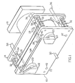
- the invention provides a robotic element 10, which comprises front and rear parallel plates 12 and 14 respectively which are non-rigidly attached to robot arm 16. Disposed between plates 12 and 14 are rotary solenoids 18 which are fixed to the rear plate 14.
- the solenoids have frontwardly projecting parts 20, which are mounted in circular holes completely through the front plate so as to be able to rotate therewithin.
- Each of the frontwardly projecting solenoids parts 20 have cassette engagement arms 22 attached as shown.
- parts 20 Upon generating the appropriate signal to the solenoid, parts 20 rotate the engagement arms 22 and thus lock into a wafer carrying cassette.
- the engagement arms preferably mate in a close tolerance fit with corresponding notches on the wafer carriers and urge the upper part of the cassette against mating lift structure 24.
- the solenoids are capable of rotary motion to either engage or disengage the cassette workpiece, however, in the most preferred embodiment, the solenoids are also capable of some degree of motion along the axis of rotation so as to be able to wiggle the cassette into exact engagement with parts 22 and 24.
- the invention uses rotary solenoids as gripping means, other gripping means such as air cylinders, motors, spring levers, linear solenoids, vacuum cylinders and the like are within the scope of the invention to impart gripping motion.
- the assembly has at least two sensor locations 26 which signal the correct placement of the workpiece cassette 31. Sensor signals are combined logically so that all the necessary conditions for a good grip are met before movement takes place. These contact points may be micro-switches which signal the correct seating of the cassette or as shown in the drawing, such may be pressure switches which are connected via hose fitting 27 to vacuum lines 28. When the cassette is correctly positioned, it will simultaneously block the flow of air through the sensors 26 and lines 28, thus signalling correct placement to the controller. If air flow is not simultaneously blocked, the solenoids are directed to move arms 22 until placement is correct, for example in cassette engagement recess 33. Otherwise, human intervention will be necessary.
- Optional post member 30 aids in placing cassette 33 by resisting any bending moment caused by parts 22 and 24 when the cassette is lifted.
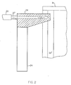
- a series of rebound springs 32 is placed between the plates 12 and 14. These assist in cushioning the impact of the plates in the event the robotic element encounters an unexpected obstacle. These rebound springs surround optional guide bars as shown. Clearly other rebound means such as rubber cushions could be used as well. Also positioned between plates 12 and 14 are impact sensors 34 which detect any amount of impact force encountered which is in excess of the amount tolerated by design. Such impact sensors signal the robot mechanism to stop when an undersirable resistive or impact force is encountered. Such may be micro-switches or as in the embodiment shown in the drawing figures are vacuum lines 36 attached to pressure switches. When air flow in the lines is unobstructed, the element is available for movement.
- Rod member 38 When the element hits an obstruction, rod member 38 is forced into a coupling engagement with receptor 40 and air flow is stopped in line 36. A signal is thereby transmitted to a switching mechanism upstream, not shown which stops the movement of the robot arm until the obstruction is cleared by human intervention.
- Rod members 38 may have their sensitivity adjusted at adjustment points 42. In practice, rods 38 are merely screws which are adjusted by turning a screw head at points 42 so their proximity to receptors 40 is changed as desired.
- Each of vacuum lines 28 and 36 may be connected to a common vacuum source without detrimental interference with sensing functions of all the sensors.
- the carrier grasp elements are not rigidly mounted on the end of a robot arm.
- the wafer carrier and grasp elements are deflected from their normal position with respect to the robot arm. This is set to occur with a small enough force that a detectable deflection occurs before the carrier is either damaged or wrenched out of a secure grip.
- the number and positioning of sensing points are selected to detect deflections caused by collisions, thereby signalling the robot control computer to immediately stop motion thereby eliminating the vast majority of situations where wafer damage would ordinarily occur.
- the non-rigid mounting of the hand assembly is designed so as not to deflect due to the weight and inertial forces caused by the carrier and wafers.
- the carrier remains in proper position with respect to the robot arm at all times.
- the construction materials are selected such that they are resilient and not damaged by collisions.
- the materials should be able to withstand the corrosive chemicals typically used in semi-conductor manufacture without deterioration.
Landscapes
- Engineering & Computer Science (AREA)
- Robotics (AREA)
- Mechanical Engineering (AREA)
- Physics & Mathematics (AREA)
- Condensed Matter Physics & Semiconductors (AREA)
- General Physics & Mathematics (AREA)
- Manufacturing & Machinery (AREA)
- Computer Hardware Design (AREA)
- Microelectronics & Electronic Packaging (AREA)
- Power Engineering (AREA)
- Container, Conveyance, Adherence, Positioning, Of Wafer (AREA)
- Manipulator (AREA)
Priority Applications (1)
| Application Number | Priority Date | Filing Date | Title |
|---|---|---|---|
| AT88402053T ATE101075T1 (de) | 1987-08-17 | 1988-08-05 | Roboterhand zum transportieren von halbleiterplaettchen. |
Applications Claiming Priority (2)
| Application Number | Priority Date | Filing Date | Title |
|---|---|---|---|
| US07/086,278 US4816732A (en) | 1987-08-17 | 1987-08-17 | Robotic hand for transporting semiconductor wafer carriers |
| US86278 | 1987-08-17 |
Publications (3)
| Publication Number | Publication Date |
|---|---|
| EP0304370A2 true EP0304370A2 (de) | 1989-02-22 |
| EP0304370A3 EP0304370A3 (de) | 1991-11-27 |
| EP0304370B1 EP0304370B1 (de) | 1994-02-02 |
Family
ID=22197492
Family Applications (1)
| Application Number | Title | Priority Date | Filing Date |
|---|---|---|---|
| EP88402053A Expired - Lifetime EP0304370B1 (de) | 1987-08-17 | 1988-08-05 | Roboterhand zum Transportieren von Halbleiterplättchen |
Country Status (6)
| Country | Link |
|---|---|
| US (1) | US4816732A (de) |
| EP (1) | EP0304370B1 (de) |
| JP (1) | JP2553472B2 (de) |
| KR (1) | KR950005079B1 (de) |
| AT (1) | ATE101075T1 (de) |
| DE (1) | DE3887597T2 (de) |
Cited By (4)
| Publication number | Priority date | Publication date | Assignee | Title |
|---|---|---|---|---|
| EP0396923A1 (de) * | 1989-05-08 | 1990-11-14 | Balzers Aktiengesellschaft | Hubtisch und Transportverfahren |
| EP0563712A1 (de) * | 1992-03-28 | 1993-10-06 | Gebrüder Junghans Gmbh | Greifer für Handhabungseinrichtungen |
| WO1993024953A1 (de) * | 1992-06-03 | 1993-12-09 | Esec S.A. | Transportroboter für eine bearbeitungs- bzw. behandlungslinie für systemträger |
| CN101987451B (zh) * | 2009-08-03 | 2013-11-20 | 鸿富锦精密工业(深圳)有限公司 | 夹紧机构及使用该夹紧机构的机械手 |
Families Citing this family (12)
| Publication number | Priority date | Publication date | Assignee | Title |
|---|---|---|---|---|
| US5271686A (en) * | 1992-01-27 | 1993-12-21 | The Budd Company | Robot hand for aligning and isolating a work tool |
| US5668452A (en) * | 1996-05-09 | 1997-09-16 | Vlsi Technology, Inc. | Magnetic sensing robotics for automated semiconductor wafer processing systems |
| US5953804A (en) * | 1998-07-10 | 1999-09-21 | Systems Engineering Company | Automated workpiece insertion method and apparatus |
| US6282459B1 (en) | 1998-09-01 | 2001-08-28 | International Business Machines Corporation | Structure and method for detection of physical interference during transport of an article |
| US6246924B1 (en) * | 1998-11-30 | 2001-06-12 | Honda Of America Mfg., Inc. | Apparatus and method for automatically realigning an end effector of an automated equipment to prevent a crash |
| DE60019713T2 (de) | 1999-02-17 | 2006-06-22 | Brooks Automation, Inc., Chelmsford | Robotische greifvorrichtung zum greifen von werkstücken mit einem an der oberseite angeortneten handgriff |
| US6695120B1 (en) | 2000-06-22 | 2004-02-24 | Amkor Technology, Inc. | Assembly for transporting material |
| US6889813B1 (en) | 2000-06-22 | 2005-05-10 | Amkor Technology, Inc. | Material transport method |
| US6530735B1 (en) * | 2000-06-22 | 2003-03-11 | Amkor Technology, Inc. | Gripper assembly |
| KR20040017614A (ko) * | 2002-08-22 | 2004-02-27 | 동부전자 주식회사 | 웨이퍼 이송 방법 |
| US9709119B2 (en) * | 2015-08-12 | 2017-07-18 | Ati Industrial Automation, Inc. | Compliance compensator |
| JP7180165B2 (ja) * | 2018-07-23 | 2022-11-30 | セイコーエプソン株式会社 | ロボット、制御装置および制御方法 |
Family Cites Families (14)
| Publication number | Priority date | Publication date | Assignee | Title |
|---|---|---|---|---|
| US3145333A (en) * | 1962-10-29 | 1964-08-18 | Pardini John Anthony | Force limiting device for motor control |
| DE1554691A1 (de) * | 1966-12-30 | 1970-01-15 | Engelhardt Hans | Vorrichtung zur Entnahme von Tuechern,Lappen od.dgl. aus einem Behaelter |
| US4179783A (en) * | 1974-12-16 | 1979-12-25 | Hitachi, Ltd. | Holding apparatus with elastic mechanism |
| US4316329A (en) * | 1979-09-19 | 1982-02-23 | The Charles Stark Draper Laboratory | Instrumented remote center compliance device |
| DE3004014A1 (de) * | 1980-02-04 | 1981-08-06 | Jungheinrich Unternehmensverwaltung Kg, 2000 Hamburg | Ueberlastsicherungsvorrichtung fuer ein handhabungsgeraet |
| JPS59353B2 (ja) * | 1980-07-24 | 1984-01-06 | ファナック株式会社 | 把持装置 |
| JPS5761487A (en) * | 1980-09-30 | 1982-04-13 | Fujitsu Fanuc Ltd | Hand for industrial robot |
| GB2127775B (en) * | 1982-09-27 | 1985-10-16 | Gen Electric Co Plc | Controlled machine limb incorporating a safety coupling |
| GB2152473B (en) * | 1984-01-12 | 1987-01-21 | British Nuclear Fuels Ltd | Improvements in compliant devices |
| US4632623A (en) * | 1984-10-15 | 1986-12-30 | United Technologies Corporation | Workpiece manipulator for a hot environment |
| DE3445849A1 (de) * | 1984-12-15 | 1986-06-19 | Dürr Automation + Fördertechnik GmbH, 7889 Grenzach-Wyhlen | Industrie-roboter |
| US4645411A (en) * | 1985-03-18 | 1987-02-24 | Albert Madwed | Gripper assembly |
| FR2581914A1 (fr) * | 1985-05-14 | 1986-11-21 | Renault | Dispositif de prehension de pieces pour robot manipulateur |
| US4672741A (en) * | 1985-06-27 | 1987-06-16 | Westinghouse Electric Corp. | End effector apparatus for positioning a steam generator heat exchanger tube plugging tool |
-
1987
- 1987-08-17 US US07/086,278 patent/US4816732A/en not_active Expired - Lifetime
-
1988
- 1988-08-05 EP EP88402053A patent/EP0304370B1/de not_active Expired - Lifetime
- 1988-08-05 DE DE3887597T patent/DE3887597T2/de not_active Expired - Fee Related
- 1988-08-05 AT AT88402053T patent/ATE101075T1/de active
- 1988-08-16 KR KR1019880010445A patent/KR950005079B1/ko not_active Expired - Fee Related
- 1988-08-16 JP JP63203674A patent/JP2553472B2/ja not_active Expired - Fee Related
Cited By (4)
| Publication number | Priority date | Publication date | Assignee | Title |
|---|---|---|---|---|
| EP0396923A1 (de) * | 1989-05-08 | 1990-11-14 | Balzers Aktiengesellschaft | Hubtisch und Transportverfahren |
| EP0563712A1 (de) * | 1992-03-28 | 1993-10-06 | Gebrüder Junghans Gmbh | Greifer für Handhabungseinrichtungen |
| WO1993024953A1 (de) * | 1992-06-03 | 1993-12-09 | Esec S.A. | Transportroboter für eine bearbeitungs- bzw. behandlungslinie für systemträger |
| CN101987451B (zh) * | 2009-08-03 | 2013-11-20 | 鸿富锦精密工业(深圳)有限公司 | 夹紧机构及使用该夹紧机构的机械手 |
Also Published As
| Publication number | Publication date |
|---|---|
| KR890003497A (ko) | 1989-04-15 |
| EP0304370B1 (de) | 1994-02-02 |
| ATE101075T1 (de) | 1994-02-15 |
| KR950005079B1 (ko) | 1995-05-18 |
| EP0304370A3 (de) | 1991-11-27 |
| JPS6471143A (en) | 1989-03-16 |
| DE3887597T2 (de) | 1994-06-30 |
| JP2553472B2 (ja) | 1996-11-13 |
| US4816732A (en) | 1989-03-28 |
| DE3887597D1 (de) | 1994-03-17 |
Similar Documents
| Publication | Publication Date | Title |
|---|---|---|
| US4816732A (en) | Robotic hand for transporting semiconductor wafer carriers | |
| US9126336B2 (en) | Compliant end of arm tooling for a robot | |
| US8862269B2 (en) | Robotic picking of parts from a bin | |
| EP2331301B1 (de) | Ergreifen von teilen aus einem behälter durch einen roboter unter verwendung von kraftrückkopplung | |
| US4813732A (en) | Apparatus and method for automated wafer handling | |
| CA1225680A (en) | Manipulator gripper tool changing apparatus | |
| CN108349090B (zh) | 用于在铰接臂中提供接触检测的系统和方法 | |
| EP1430513B1 (de) | Gegenstandshalter mit sensoren zur bestimmung der art des artikels, welcher durch den halter gehalten wird | |
| US6652217B2 (en) | System and method for separating double blanks | |
| JPH05138570A (ja) | 電動モーターの部品などのグリツパー装置 | |
| US20070001638A1 (en) | Robot with vibration sensor device | |
| JPS61226287A (ja) | 加工品を取扱うたぬの装置および方法 | |
| Tella et al. | General purpose hands for bin-picking robots | |
| WO2017155094A1 (ja) | 電子部品実装装置および電子部品の実装方法 | |
| EP0090060B1 (de) | Kontaktfühlervorrichtung | |
| US20210118719A1 (en) | Dual Arm with Opposed Dual End Effectors and No Vertical Wafer Overlap | |
| US6246924B1 (en) | Apparatus and method for automatically realigning an end effector of an automated equipment to prevent a crash | |
| JP4156822B2 (ja) | ハンドリング装置 | |
| CN115485108A (zh) | 用于操作拣拾机器人的方法及相关装置 | |
| JPS61168481A (ja) | センサー及びセンサーを用いた制御システム | |
| US20250214263A1 (en) | Robot assembly for processing and/or handling a workpiece, protection element for a robot assembly, and protection assembly | |
| JPH02291144A (ja) | ウェーハ搬送装置 | |
| Kelley et al. | A robot system which acquires cylindrical workpieces from bins | |
| JPS63120092A (ja) | 把持装置 | |
| EP3875231A1 (de) | Endeffektoranordnung für einen kommissionierroboter, werkzeugeinheit und kommissionierroboter |
Legal Events
| Date | Code | Title | Description |
|---|---|---|---|
| PUAI | Public reference made under article 153(3) epc to a published international application that has entered the european phase |
Free format text: ORIGINAL CODE: 0009012 |
|
| AK | Designated contracting states |
Kind code of ref document: A2 Designated state(s): AT CH DE ES FR GB IT LI NL SE |
|
| PUAL | Search report despatched |
Free format text: ORIGINAL CODE: 0009013 |
|
| AK | Designated contracting states |
Kind code of ref document: A3 Designated state(s): AT CH DE ES FR GB IT LI NL SE |
|
| 17P | Request for examination filed |
Effective date: 19920125 |
|
| 17Q | First examination report despatched |
Effective date: 19920716 |
|
| GRAA | (expected) grant |
Free format text: ORIGINAL CODE: 0009210 |
|
| AK | Designated contracting states |
Kind code of ref document: B1 Designated state(s): AT CH DE ES FR GB IT LI NL SE |
|
| PG25 | Lapsed in a contracting state [announced via postgrant information from national office to epo] |
Ref country code: SE Effective date: 19940202 Ref country code: NL Effective date: 19940202 Ref country code: LI Effective date: 19940202 Ref country code: ES Free format text: THE PATENT HAS BEEN ANNULLED BY A DECISION OF A NATIONAL AUTHORITY Effective date: 19940202 Ref country code: CH Effective date: 19940202 Ref country code: AT Effective date: 19940202 |
|
| REF | Corresponds to: |
Ref document number: 101075 Country of ref document: AT Date of ref document: 19940215 Kind code of ref document: T |
|
| ITF | It: translation for a ep patent filed | ||
| REF | Corresponds to: |
Ref document number: 3887597 Country of ref document: DE Date of ref document: 19940317 |
|
| ET | Fr: translation filed | ||
| REG | Reference to a national code |
Ref country code: CH Ref legal event code: PL |
|
| NLV1 | Nl: lapsed or annulled due to failure to fulfill the requirements of art. 29p and 29m of the patents act | ||
| PLBE | No opposition filed within time limit |
Free format text: ORIGINAL CODE: 0009261 |
|
| STAA | Information on the status of an ep patent application or granted ep patent |
Free format text: STATUS: NO OPPOSITION FILED WITHIN TIME LIMIT |
|
| 26N | No opposition filed | ||
| PGFP | Annual fee paid to national office [announced via postgrant information from national office to epo] |
Ref country code: DE Payment date: 19980817 Year of fee payment: 11 |
|
| PG25 | Lapsed in a contracting state [announced via postgrant information from national office to epo] |
Ref country code: DE Free format text: LAPSE BECAUSE OF NON-PAYMENT OF DUE FEES Effective date: 20000601 |
|
| PGFP | Annual fee paid to national office [announced via postgrant information from national office to epo] |
Ref country code: GB Payment date: 20010801 Year of fee payment: 14 |
|
| PGFP | Annual fee paid to national office [announced via postgrant information from national office to epo] |
Ref country code: FR Payment date: 20010810 Year of fee payment: 14 |
|
| REG | Reference to a national code |
Ref country code: GB Ref legal event code: IF02 |
|
| PG25 | Lapsed in a contracting state [announced via postgrant information from national office to epo] |
Ref country code: GB Free format text: LAPSE BECAUSE OF NON-PAYMENT OF DUE FEES Effective date: 20020805 |
|
| GBPC | Gb: european patent ceased through non-payment of renewal fee |
Effective date: 20020805 |
|
| PG25 | Lapsed in a contracting state [announced via postgrant information from national office to epo] |
Ref country code: FR Free format text: LAPSE BECAUSE OF NON-PAYMENT OF DUE FEES Effective date: 20030430 |
|
| REG | Reference to a national code |
Ref country code: FR Ref legal event code: ST |
|
| PG25 | Lapsed in a contracting state [announced via postgrant information from national office to epo] |
Ref country code: IT Free format text: LAPSE BECAUSE OF NON-PAYMENT OF DUE FEES Effective date: 20050805 |