EP0303989B1 - Raccord droit pour deux éléments de tuyaux concentriques - Google Patents
Raccord droit pour deux éléments de tuyaux concentriques Download PDFInfo
- Publication number
- EP0303989B1 EP0303989B1 EP19880113155 EP88113155A EP0303989B1 EP 0303989 B1 EP0303989 B1 EP 0303989B1 EP 19880113155 EP19880113155 EP 19880113155 EP 88113155 A EP88113155 A EP 88113155A EP 0303989 B1 EP0303989 B1 EP 0303989B1
- Authority
- EP
- European Patent Office
- Prior art keywords
- tube
- collar
- butt joint
- sections
- joint according
- Prior art date
- Legal status (The legal status is an assumption and is not a legal conclusion. Google has not performed a legal analysis and makes no representation as to the accuracy of the status listed.)
- Expired - Lifetime
Links
Images


Classifications
-
- F—MECHANICAL ENGINEERING; LIGHTING; HEATING; WEAPONS; BLASTING
- F23—COMBUSTION APPARATUS; COMBUSTION PROCESSES
- F23J—REMOVAL OR TREATMENT OF COMBUSTION PRODUCTS OR COMBUSTION RESIDUES; FLUES
- F23J13/00—Fittings for chimneys or flues
- F23J13/02—Linings; Jackets; Casings
- F23J13/025—Linings; Jackets; Casings composed of concentric elements, e.g. double walled
-
- F—MECHANICAL ENGINEERING; LIGHTING; HEATING; WEAPONS; BLASTING
- F16—ENGINEERING ELEMENTS AND UNITS; GENERAL MEASURES FOR PRODUCING AND MAINTAINING EFFECTIVE FUNCTIONING OF MACHINES OR INSTALLATIONS; THERMAL INSULATION IN GENERAL
- F16L—PIPES; JOINTS OR FITTINGS FOR PIPES; SUPPORTS FOR PIPES, CABLES OR PROTECTIVE TUBING; MEANS FOR THERMAL INSULATION IN GENERAL
- F16L37/00—Couplings of the quick-acting type
- F16L37/56—Couplings of the quick-acting type for double-walled or multi-channel pipes or pipe assemblies
- F16L37/565—Concentric pipes
-
- F—MECHANICAL ENGINEERING; LIGHTING; HEATING; WEAPONS; BLASTING
- F16—ENGINEERING ELEMENTS AND UNITS; GENERAL MEASURES FOR PRODUCING AND MAINTAINING EFFECTIVE FUNCTIONING OF MACHINES OR INSTALLATIONS; THERMAL INSULATION IN GENERAL
- F16L—PIPES; JOINTS OR FITTINGS FOR PIPES; SUPPORTS FOR PIPES, CABLES OR PROTECTIVE TUBING; MEANS FOR THERMAL INSULATION IN GENERAL
- F16L39/00—Joints or fittings for double-walled or multi-channel pipes or pipe assemblies
-
- F—MECHANICAL ENGINEERING; LIGHTING; HEATING; WEAPONS; BLASTING
- F23—COMBUSTION APPARATUS; COMBUSTION PROCESSES
- F23J—REMOVAL OR TREATMENT OF COMBUSTION PRODUCTS OR COMBUSTION RESIDUES; FLUES
- F23J13/00—Fittings for chimneys or flues
- F23J13/04—Joints; Connections
-
- F—MECHANICAL ENGINEERING; LIGHTING; HEATING; WEAPONS; BLASTING
- F23—COMBUSTION APPARATUS; COMBUSTION PROCESSES
- F23J—REMOVAL OR TREATMENT OF COMBUSTION PRODUCTS OR COMBUSTION RESIDUES; FLUES
- F23J2211/00—Flue gas duct systems
- F23J2211/10—Balanced flues (combining air supply and flue gas exhaust)
- F23J2211/101—Balanced flues (combining air supply and flue gas exhaust) with coaxial duct arrangement
-
- F—MECHANICAL ENGINEERING; LIGHTING; HEATING; WEAPONS; BLASTING
- F23—COMBUSTION APPARATUS; COMBUSTION PROCESSES
- F23J—REMOVAL OR TREATMENT OF COMBUSTION PRODUCTS OR COMBUSTION RESIDUES; FLUES
- F23J2213/00—Chimneys or flues
- F23J2213/20—Joints; Connections
- F23J2213/202—Joints; Connections between duct or stack sections
-
- F—MECHANICAL ENGINEERING; LIGHTING; HEATING; WEAPONS; BLASTING
- F23—COMBUSTION APPARATUS; COMBUSTION PROCESSES
- F23J—REMOVAL OR TREATMENT OF COMBUSTION PRODUCTS OR COMBUSTION RESIDUES; FLUES
- F23J2213/00—Chimneys or flues
- F23J2213/20—Joints; Connections
- F23J2213/203—Joints; Connections between stack/duct and combustion apparatus
Definitions
- the invention relates to a butt joint for pipe sections consisting of two concentric pipes of different diameters (outer and inner pipe), in particular exhaust gases and combustion air from gas burners, wherein at least the inner pipes of this pipe section are connected to one another by means of a sleeve which forms a distance between the end faces of the pipe sections bridged.
- the object of the invention is to provide a butt joint of such pipes which can be produced even under comparatively difficult local conditions without any particular expenditure of time and effort lets, for example, even if one of the two pipe sections to be connected to one another is stationary and the other pipe section can only be brought to the end of the pipe section in a direction perpendicular to the axis of this stationary pipe section, such as when installing an exhaust gas and supply air duct burner-heated wall unit that is to be connected to a combined exhaust gas / fresh air duct already embedded in the wall.
- the sleeve is from a position in which it is pushed or pushed into or onto the inner or outer pipe of one of the two pipe sections to be connected and its free edge is axially spaced from the end face of the inner or outer pipe of the other pipe section, in a position connecting the inner or outer tubes of these pipe sections, in which it is then pushed onto or into the inner or outer pipe of the other pipe section.
- an initially movable pipe section can be brought up to a fixed pipe section in a direction perpendicular to its axis and then, as soon as the pipe sockets run coaxially, can be connected to this stationary pipe section by a simple axial displacement of the sleeve.
- the main feature of this solution is that it is easy to use and provides a reliable connection.
- the sleeve is in a position in which it is pushed or pushed into or onto the inner or outer tube of one of the two pipe sections to be connected and its free edge on the end face of the inner or outer pipe of the other pipe section opposite with an axial distance, in a position connecting the inner or outer tubes of these pipe sections, in which it is then pushed onto or into the inner or outer pipe of the other pipe section.
- This embodiment is characterized in that it is easy to use and provides a reliable connection.
- the sleeve expediently consists of two mutually offset sections, one of which has an inner diameter which corresponds to the outer diameter of the inner or outer tube of one of the two pipe sections to be connected, and the other has an outer diameter which corresponds to the inner diameter of the inner or Outer tube of the other of the two pipe sections to be connected corresponds,
- the minimum length of one of the two pipe sections of the sleeve should be the maximum distance between the end faces of the inner or. Outer pipes of the two pipe sections to be connected correspond.
- such coupling members can consist of an angled guide formed on the sleeve and a pin which projects into one of the two pipe sections to be connected and projects into this guide.
- a coupling member which consists of a screw which penetrates the wall of the sleeve in a bore, possibly a threaded bore.
- a screw can simply act as a clamping screw on the wall of the tube stored in the sleeve, but it can also engage in a bore, possibly a threaded bore, in the wall of the inner or outer tube of one of the pipe sockets to be connected.
- the invention can be implemented in various variants.
- only the inner tubes of the tube sections to be connected can be connected a displaceable sleeve
- the outer tubes on the other hand, are connected by means of a tube clamp bridging the distance between their end faces.
- the advantageous possibility is open within the scope of the invention to connect both the inner tubes and the outer tubes of the tube sections to be connected to one another by means of a displaceable sleeve that bridges the distances between their end faces.
- various variants can be designed to suit the purpose of the pipes.
- both the inner tubes and the outer tubes connecting sleeves of one of the two tube sections to be connected to each other can the inner or.
- the sleeve of the outer pipe of one of the two pipe sections is advantageously in the outer pipe of the other Pipe section inserted, but the sleeve of the inner pipe of this one pipe section pushed onto the inner pipe of the other pipe section, so that the sections of the cuffs pushed onto the ends of the inner and outer pipes each point against the predetermined flow direction of the media flowing in these pipes, causing leakage of the medium at the butt joint is effectively prevented.
- connection between the sleeves and the tubes embodying the pipe sections can be made even more intimate in the context of the invention if the sleeve has ring slots on their two end faces for inserting the front ends of the inner and outer pipes of the two pipe sections to be connected, the width of which corresponds approximately to the thickness of the walls of the pipe sections.
- such ring slots on the two end faces can be made unequal in depth, the minimum depth of the deeper ring slot corresponding to the maximum distance between the two pipe sections to be connected.
- Such a sleeve can then be largely pushed onto one of the pipes of the pipe sections with its deeper slot so that it does not hinder the installation of the adjacent pipe section.
- the ring slots can be molded or incorporated into the material of the sleeves, but such a ring slot can be formed particularly easily by the sleeve containing a tubular lining with an outer bead which limits the slot depth and which lies against the inner wall of the sleeve.
- the sleeves can optionally be formed on their inner wall with longitudinal strips with an outwardly projecting bead which limits the insertion depth and which abuts the inner wall of the sleeves and delimits slots on both sides.
- the aforementioned lining or the aforementioned strips can easily be attached to the inside of the wall of the sleeve by means of recesses in the sleeve wall, which engage in recesses in the lining or the strips.
- Such recesses can also be designed as threaded holes; they are expediently provided in the vicinity of the two end faces of the cuff or the lining or the strips.
- the collars according to the invention can also be used if pipe sections of different diameters are to be connected to one another, in this case they can be formed with a shoulder.
- the easiest way to do this is to form such a step between the two aforementioned longitudinal sections of the sleeve facing the pipes of the pipe sections to be connected.
- a deposit can be arranged in the area of the aforementioned annular bead of the lining of the cuff, preferably running next to this annular bead.
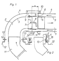
- the sleeve 5 is in the state shown with solid lines with a section whose outer diameter corresponds to the inner diameter of the inner tube 3 of the pipe section 1 and is inserted into this inner pipe and its end face is at a short distance c from the end face of the inner pipe 3 of the pipe section 2.
- the sleeve bridges the distance a between the free end faces of the inner tubes 3 and can be locked in this position by coupling members.
- these coupling members consist of an angularly extending guide 8 formed on the sleeve 5 and of a pin 7 protruding at the end of the inner tube 3 of the pipe socket 2 and fitting into the guide 8.
- the wall of the sleeve 5 in is a coupling member a bore, optionally penetrating a threaded bore, screw 9 is provided, which either presses clampingly against the wall of the inner tube 3 or engages in a bore, optionally a threaded bore of this wall.
- 1 shows the connection of the curved pipe section 2 to the mouth of an exhaust gas duct 11 of a burner-heated device housed in a housing 12, for example a water heater.
- the inner pipe 3 of the pipe section 2 is simply plugged onto the mouth of the exhaust gas duct 11.
- the outer tube 4 on the other hand, is inserted into an annular flange 13 of the housing 12 and is fastened to the annular flange 13 with radially arranged screws 14 passing through elongated holes.
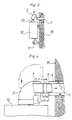
- a fastening according to FIG. 2 could also be provided, with a tab 15 in combination with the ring flange 13 or a clamp tightly enclosing the stepped end of the outer tube 4.
- FIG 3 shows a side view of the arrangement of the burner-heated device on the inside (room side) of a building, illustrating the problem that occurs when the curved pipe section 2, on the one hand, has the end of a straight pipe section embedded in the outer wall 16 1 and on the other hand to be connected to the ring flange 13 of the housing 12 of the device attached to the outer wall 16 and connected to a supply line 17.
- the sleeve 5 (in the drawing to the left) needs to be pushed onto the end of the inner tube 3 of the pipe section 2 and the pipe clamp 10 according to FIG. 1 is mounted to complete the connection to bridge the distance b between the end faces of the outer pipes 4
- the sleeve 5 bridges the distance a between the free end faces of the inner tubes 3 of the two pipe sections 1 and 2. It is essential that the minimum length of the protruding longitudinal section of the sleeve 5 corresponds to the maximum distance a between the end sides of the inner pipes 3 of the pipe sections 1 and 2.
- both the sleeves 5 of the outer tubes 4 and the sleeves 5 of the inner tubes 3 of one tube section overlap the ends of the outer and inner tubes 4 and 3 of the tube section 2.
- the inner pipe is used, for example, to guide the exhaust gas and the outer pipe is used to guide the combustion air flowing in countercurrent, then it is advisable to point the sections of the sleeves 5 that respectively encase the pipe ends against the direction of flow indicated by arrows of the media conveyed in these pipe sections 1 and 2 to leave, as shown in Fig.6.
- the sleeve 5 of the outer tube 4 of the pipe section 1 is pushed into the outer pipe 4 of the pipe section 2, but the sleeve 5 of the inner pipe of the pipe section 5 is pushed onto the inner pipe 3 of the pipe section 2.
- the shoulders between the two sections of the cuffs therefore serve as stops which limit the insertion depth.
- the distance b between the end faces of the outer tubes 4 must in any case be so large that the sleeve 5 of the inner tubes 3 can be handled without difficulty.
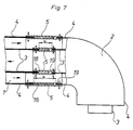
- the sleeves 5 have on their two end faces suitable ring slots 18 and 19 for inserting the end ends of the walls of the two pipe sections 1 and 2 to be connected, the width of which is approximately the same thickness as the pipe walls corresponds to pipe sections 1 and 2.
- These ring slots 18 and 19 are not the same depth and the depth of the deeper slots 18 is in any case greater than the clear one Distance a from the end faces of the inner tubes 3 of the tube sections 1 and 2 to be connected to one another.
- the sleeve 5 to form the ring slots 18 and 19 a tubular lining 20 with an adjacent to the inner wall of the sleeve 5 and the slot depth on both sides contain annular bead 21, for example in variants such as the upper and 8, can be profiled. If no requirements are imposed on the tightness of the butt joint, such as, for example, in the case of a fresh air duct, it may be sufficient if the sleeve 5 has longitudinal strips 22 attached to its inner wall to limit the insertion depth for the ends of the pipes 3 and 4 of the pipe sections 1 and 2 outwardly projecting beads 23 which distance the strips 22 from the inner wall.
- Such liners 20 or strips 22 can be fastened to the wall of the cuff 5 by means of recesses 24 in the cuff wall, which engage in recesses 25 of the liner 20 or the strips 22.
- these recesses 25 of the chuck 20 or the strips 22 can also be designed as threaded bores according to FIG.
- the tube ends of the tubes to be inserted into the slots formed in this way can have perforations in order to allow the shafts of the fastening screws to pass through. If necessary, slots can also be arranged so that the screws do not have to be removed when the tubes are inserted.
- FIG. 11 shows a butt joint, the sleeve 5 of which has a shoulder for the connection of pipe sections of different diameters between its two longitudinal sections.
- this shoulder 26 is arranged in the region of the annular bead 21 of the chuck 20, preferably running next to this annular bead 21.
Landscapes
- Engineering & Computer Science (AREA)
- General Engineering & Computer Science (AREA)
- Mechanical Engineering (AREA)
- Quick-Acting Or Multi-Walled Pipe Joints (AREA)
- Joints Allowing Movement (AREA)
- Mutual Connection Of Rods And Tubes (AREA)
- Non-Disconnectible Joints And Screw-Threaded Joints (AREA)
- Rigid Pipes And Flexible Pipes (AREA)
- Fittings On The Vehicle Exterior For Carrying Loads, And Devices For Holding Or Mounting Articles (AREA)
- Infusion, Injection, And Reservoir Apparatuses (AREA)
Claims (22)
- Moyen d'assemblage bout à bout pour deux éléments de tuyauterie comprenant chacun deux tuyaux concentriques de diamètre différent (tuyaux extérieur et intérieur) notamment pour la canalisatioin des gaz brûlés et de l'air de combustion de brûleurs à gaz, où au moins les tuyaux intérieurs de ces éléments sont assemblés entre eux par un manchon qui couvre une distance séparant les bouts des éléments de tuyauterie, caractérisé par le fait que le manchon (5), depuis une position dans laquelle il est introduit dans ou glissé sur le tuyau intérieur ou le tuyau extérieur (3 ou 4) de l'un (1 ou 2) des deux éléments de tuyauterie (t et 2) à assembler et où son bout libre se trouve à une distance axiale (c) du bout du tuyau intérieur ou extérieur (3 ou 4) de l'autre élément de tuyauterie (2 ou 1), peut être mis dans une position où il assemble les tuyaux intérieur ou extérieur (3 ou 4) après qu'il a été introduit dans ou glissé sur le tuyau intérieur ou extérieur (3 ou 4) de l'autre élément de tuyauterie (2 ou 1).
- Moyen d'assemblage bout à bout suivant la revendication 1, caractérisé par le fait que le manchon (5) comprend deux parties étagées l'une par rapport à l'autre dont l'une a un diamètre intérieur qui correspond au diamètre extérieur du tuyau intérieur ou extérieur (3 ou 4) de l'un (1 ou 2) des deux éléments de tuyauterie (1 et 2) à assembler, et l'autre a un diamètre extérieur qui correspond au diamètre intérieur du tuyau intérieur ou extérieur (3 ou 4) de l'autre (2 ou 1) des deux éléments de tuyauterie (1 et 2) à assembler (Fig. 1, 4 à 6).
- Moyen d'assemblage bout à bout suivant la revendication 2, caractérisé par le fait que la longueur mini de l'une des deux parties du manchon est égale à la distance maxi (a ou b) entre les bouts des tuyaux intérieur ou extérieur (3 ou 4) des deux éléments de tuyauterie (1 et 2) à assembler (Fig. 1 et 4 à 6).
- Moyen d'assemblage bout à bout suivant l'une des revendications 1 à 3, caractérisé par des auxiliaires d'accouplement (7 - 9) pour fixer le manchon (5) dans sa position assurant l'assemblage des tuyaux intérieurs ou extérieurs (3 ou 4) des éléments de tuyauterie (1 et 2) à assembler (Fig. 1).
- Moyen d'assemblage bout à bout suivant la revendication 4, caractérisé par le fait que les auxiliaires d'accouplement se composent d'une coulisse coudée (8) pratiquée dans le manchon (5) et d'un doigt (7) adapté à cette coulisse (8) et monté au bout de l'un (1 ou 2) des deux éléments de tuyauterie (1 et 2) à assembler (Fig. 1).
- Moyen d'assemblage bout à bout suivant l'une des revendications 1 à 5, caractérisé par un organe de manipulation (6) disposé radialement sur l'extérieur du manchon (5) et servant à déplacer et éventuellement à faire tourner ledit manchon (Fig. 1).
- Moyen d'assemblage bout à bout suivant l'une des revendications 4 à 6, caractérisé par le fait qu'un auxiliaire d'accouplement est constitué par une vis (9) logée dans un alésage, éventuellement un taraudage, pratiqué dans la paroi du manchon (5) (Fig. 1).
- Moyen d'assemblage bout à bout suivant la revendication 7, caractérisé par le fait qu'il est prévu pour la vis (9) un alésage, éventuellement un taraudage, dans la paroi du tuyau intérieur ou extérieur (3 ou 4) de l'un des éléments de tuyauterie (1 et 2) à assembler (Fig. 1).
- Moyen d'assemblage bout à bout suivant l'une des revendications 1 à 8, caractérisé par le fait que seuls les tuyaux intérieurs (3) des éléments de tuyauterie (1 et 2) à assembler sont réunis par un manchon (5) mobile, tandis que les tuyaux extérieurs (4) le sont au moyen d'un collier (10) couvrant la distance (b) entre leurs bouts (Fig. 1).
- Moyen d'assemblage bout à bout suivant l'une des revendications 1 à 8, caractérisé par le fait qu'aussi bien les tuyaux intérieurs (3) que les tuyaux extérieurs (4) des éléments de tuyauterie (1 et 2) à assembler sont réunis entre eux par un manchon (5) mobile couvrant les distances (a ou b) entre leurs bouts respectifs (Fig. 5, 6).
- Moyen d'assemblage bout à bout suivant la revendication 10, caractérisé par le fait que les manchons (5) réunissant les tuyaux intérieurs (3) et les tuyaux extérieurs (4) de l'un (1 ou 2) des deux éléments de tuyauterie (1 et 2) à assembler, dépassent le diamètre du tuyau intérieur ou extérieur (3 ou 4) de l'autre élément de tuyauterie (2 ou 1) et sont glissés dans le même sens sur les bouts de ces tuyaux (3 ou 4) (Fig. 6).
- Moyen d'assemblage bout à bout suivant la revendication 10, caractérisé par le fait que le manchon (5) du tuyau extérieur (4) de l'un (1 ou 2) des deux éléments de tuyauterie (1 et 2) est introduit dans le tuyau extérieur (4) de l'autre élément de tuyauterie (2 ou 1), tandis que le manchon (5) du tuyau intérieur (3) de cet élément de tuyauterie (1 ou 2) est glissé sur le tuyau intérieur (3) de l'autre élément de tuyauterie (2 ou 1) (Fig. 5).
- Moyen d'assemblage bout à bout suivant la revendication 12, caractérisé par le fait que les parties du manchon (5) appliquées aux bouts des tuyaux intérieurs ou extérieurs (3 ou 4) sont orientées contrairement au sens d'écoulement des fluides circulant dans ces tuyaux (3, 4) (Fig. 5).
- Moyen d'assemblage bout à bout suivant la revendication 1, caractérisé par le fait que le manchon (5) présente à ses deux extrémités des rainures annulaires (18 et 19) où sont introduits les bouts du tuyau intérieur ou extérieur (3 ou 4) des deux éléments de tuyauterie (1 et 2) à assembler, et dont la section correspond à peu près à l'épaisseur des parois des éléments de tuyauterie (1, 2) (Fig. 7 à 11).
- Moyen d'assemblage bout à bout suivant la revendication 14, caractérisé par le fait que les rainures annulaires (18 et 19) n'ont pas la même profondeur, la profondeur mini de la rainure plus profonde (18) correspondant à la distance maxi (a ou b) entre les deux éléments de tuyauterie (1, 2) à assembler.
- Moyen d'assemblage bout à bout suivant la revendication 14 ou 15, caractérisé par le fait que le manchon (5) comprend une doublure tubulaire (20) comportant un bourrelet (21) délimitant la profondeur des rainures (18 et 19) et s'appliquant contre la paroi intérieure du manchon (5) (Fig. 8).
- Moyen d'assemblage bout à bout suivant la revendication 1, caractérisé par le fait que le manchon (5) porte à sa paroi intérieure, pour délimiter la profondeur de pénétration des bouts des tuyaux intérieurs ou extérieurs (3 ou 4) des éléments de tuyauterie (1 et 2), des baguettes (22) munies d'un bourrelet (23) délimitant ladite profondeur et s'appliquant contre la paroi intérieure du manchon (5) pour former ainsi des rainures (18 et 19) s'étendant de part et d'autre (Fig. 9).
- Moyen d'assemblage bout à bout suivant la revendication 16 ou 17, caractérisé par le fait que la doublure (20) respectivement les baguettes (22) sont fixées sur la paroi intérieure du manchon (5) à l'aide de vis logées dans des trous (24) de la paroi du manchon (5) et dans des trous (25) de la doublure (20) respectivement de la baguette (22) (Fig. 8 à 10).
- Moyen d'assemblage bout à bout suivant la revendication 18, caractérisé par le fait que les trous (25) dans la doublure (20) ou les baguettes (22) sont des taraudages (Fig. 10).
- Moyen d'assemblage bout à bout suivant la revendication 18 ou 19, caractérisé par le fait que les trous (24 ou 25) sont prévus à proximité des deux bouts du manchon (5) ou de la doublure (20) respectivement des baguettes (22) (Fig. 8, 9).
- Moyen d'assemblage bout à bout suivant l'une des revendications 2 à 20, caractérisé par le fait que le manchon (5) pour l'assemblage d'éléments de tuyauterie (1, 2) de diamètre différent comporte entre ses deux parties un épaulement (26) (Fig. 11).
- Moyen d'assemblage bout à bout suivant les revendications 16 et 21, caractérisé par le fait que l'épaulement (26) est prévu à proximité du bourrelet (21) de la doublure (20) du manchon (5), de préférence à côté dudit bourrelet (21) (Fig. 11).
Applications Claiming Priority (2)
| Application Number | Priority Date | Filing Date | Title |
|---|---|---|---|
| AT207087 | 1987-08-18 | ||
| AT2070/87 | 1987-08-18 |
Publications (3)
| Publication Number | Publication Date |
|---|---|
| EP0303989A2 EP0303989A2 (fr) | 1989-02-22 |
| EP0303989A3 EP0303989A3 (en) | 1989-12-20 |
| EP0303989B1 true EP0303989B1 (fr) | 1993-02-10 |
Family
ID=3527132
Family Applications (1)
| Application Number | Title | Priority Date | Filing Date |
|---|---|---|---|
| EP19880113155 Expired - Lifetime EP0303989B1 (fr) | 1987-08-18 | 1988-08-11 | Raccord droit pour deux éléments de tuyaux concentriques |
Country Status (3)
| Country | Link |
|---|---|
| EP (1) | EP0303989B1 (fr) |
| AT (1) | ATE85678T1 (fr) |
| DE (2) | DE3878344D1 (fr) |
Cited By (1)
| Publication number | Priority date | Publication date | Assignee | Title |
|---|---|---|---|---|
| DE102009052674A1 (de) * | 2009-11-12 | 2011-05-19 | Weinhold, Karl, Dipl.-Ing. | Vorrichtung zum Verbinden von Doppelmantelrohren |
Families Citing this family (9)
| Publication number | Priority date | Publication date | Assignee | Title |
|---|---|---|---|---|
| FR2662198B1 (fr) * | 1990-05-18 | 1992-08-14 | Haesebrouck Francis | Colonne de vide-ordures. |
| FR2712745B1 (fr) * | 1993-11-15 | 1996-02-09 | Entrepose Montalev | Dispositif de gaine de pour câbles. |
| WO1996033365A1 (fr) * | 1995-04-21 | 1996-10-24 | Entrepose-Montalev | Dispositif de gaine pour cables |
| DE29810921U1 (de) * | 1998-06-18 | 1999-11-04 | Bosch Gmbh Robert | Abgasanschluß für gasbeheizte Wandgeräte, insbesondere Wassererhitzer |
| IT1305428B1 (it) * | 1998-12-17 | 2001-05-04 | Cast S R L | Condotto di scarico gas di combustione ed aspirazione gas comburenti |
| AT408800B (de) * | 2000-07-10 | 2002-03-25 | Vaillant Gmbh | Ausgleichseinrichtung für eine kombinierte luft-/abgasführung |
| AT503704B1 (de) * | 2000-08-18 | 2008-06-15 | Vaillant Gmbh | Anschlusseinrichtung |
| FR2986606A1 (fr) * | 2012-02-07 | 2013-08-09 | Anais Leroux | Conduit de fumee |
| FR3028303B1 (fr) * | 2014-11-12 | 2016-12-30 | Commissariat Energie Atomique | Dispositif de connexion fluidique d'une ligne fluidique double enveloppe comportant des premier et deuxieme connecteurs fluidiques |
Citations (1)
| Publication number | Priority date | Publication date | Assignee | Title |
|---|---|---|---|---|
| US3896855A (en) * | 1974-03-12 | 1975-07-29 | Chronister Dev Inc | Multiported valve |
Family Cites Families (6)
| Publication number | Priority date | Publication date | Assignee | Title |
|---|---|---|---|---|
| US2650112A (en) * | 1949-02-02 | 1953-08-25 | Williams Wallace Company | Double walled pipe and coupling therefor |
| US2896855A (en) * | 1958-06-18 | 1959-07-28 | Don O Neville | Chemical applicator for use with internal combustion engines |
| DE1870244U (de) * | 1963-01-17 | 1963-04-11 | Linde Eismasch Ag | Kupplungsstueck zur gasdichten loetverbindung der stossstellen ineinander liegender rohre. |
| FR2350539A1 (fr) * | 1976-05-07 | 1977-12-02 | Saunier Duval | Coude de raccordement pour deux tubes concentriques |
| DE3427745A1 (de) * | 1984-07-27 | 1986-02-06 | Heinz Mayer GmbH, Maschinenbau, 7311 Holzmaden | Anschlusskupplung fuer behaelter |
| GB2177768A (en) * | 1985-06-21 | 1987-01-28 | R J Brown And Associates | Replaceable seals for pipelines |
-
1988
- 1988-08-11 DE DE8888113155T patent/DE3878344D1/de not_active Expired - Fee Related
- 1988-08-11 AT AT88113155T patent/ATE85678T1/de not_active IP Right Cessation
- 1988-08-11 EP EP19880113155 patent/EP0303989B1/fr not_active Expired - Lifetime
- 1988-08-11 DE DE8810212U patent/DE8810212U1/de not_active Expired
Patent Citations (1)
| Publication number | Priority date | Publication date | Assignee | Title |
|---|---|---|---|---|
| US3896855A (en) * | 1974-03-12 | 1975-07-29 | Chronister Dev Inc | Multiported valve |
Cited By (1)
| Publication number | Priority date | Publication date | Assignee | Title |
|---|---|---|---|---|
| DE102009052674A1 (de) * | 2009-11-12 | 2011-05-19 | Weinhold, Karl, Dipl.-Ing. | Vorrichtung zum Verbinden von Doppelmantelrohren |
Also Published As
| Publication number | Publication date |
|---|---|
| EP0303989A3 (en) | 1989-12-20 |
| DE3878344D1 (de) | 1993-03-25 |
| DE8810212U1 (fr) | 1988-09-22 |
| EP0303989A2 (fr) | 1989-02-22 |
| ATE85678T1 (de) | 1993-02-15 |
Similar Documents
| Publication | Publication Date | Title |
|---|---|---|
| EP0806597B1 (fr) | Raccord rapide | |
| EP0303989B1 (fr) | Raccord droit pour deux éléments de tuyaux concentriques | |
| DE4010556A1 (de) | Doppellagiger rohrbogen | |
| DE2201306C3 (de) | Rohrkupplung | |
| DE2632456C2 (de) | Injektionsvorrichtung für einen Doppelrohr-Bohrstrang | |
| DE8307717U1 (de) | Schlauchkupplung | |
| DE2327050B1 (de) | Rohrverbindung | |
| EP0398252B1 (fr) | Tube radiant avec enveloppe | |
| DE19547677C2 (de) | Kaminrohr für die Schornsteinsanierung | |
| DE4016124C2 (de) | Rohrverbindung mit gezahnter Dichtung | |
| DE4040638C2 (de) | Rohrverbindung | |
| DE3842436C2 (fr) | ||
| DE2819254A1 (de) | Rohrverbindung | |
| EP0959291A2 (fr) | Raccord de tuyau | |
| DE3447802C1 (de) | Abdeckung an einer Wasserauslauf-Armatur | |
| DE2044492C3 (de) | Brennrohr Anschlußkupplung | |
| DE1475860A1 (de) | Rohrkupplung | |
| CH712158B1 (de) | Schlauch, insbesondere Brauseschlauch. | |
| EP1116544A2 (fr) | Appareil pour le remplissage de gaz | |
| DE3739706A1 (de) | Verbinder | |
| EP1262706B1 (fr) | Raccord pour relier coaxialement des tuyaux flexibles | |
| EP0458289A1 (fr) | Connexion pour tubes de forage ou analogues | |
| DE3216553A1 (de) | Anschlussstueck fuer mehradrige hydraulische oder pneumatische schlauchleitungen, insbesondere fuer hydraulische ausbausysteme | |
| DE3310569A1 (de) | Be- und entlueftungsanlage fuer mehrgeschossige bauwerke | |
| DE19509579C2 (de) | Rohrelement zum Erstellen von Schornsteinen sowie von Abgas- und Abdampfleitungen |
Legal Events
| Date | Code | Title | Description |
|---|---|---|---|
| PUAI | Public reference made under article 153(3) epc to a published international application that has entered the european phase |
Free format text: ORIGINAL CODE: 0009012 |
|
| AK | Designated contracting states |
Kind code of ref document: A2 Designated state(s): AT BE CH DE ES FR GB GR IT LI LU NL SE |
|
| PUAL | Search report despatched |
Free format text: ORIGINAL CODE: 0009013 |
|
| AK | Designated contracting states |
Kind code of ref document: A3 Designated state(s): AT BE CH DE ES FR GB GR IT LI LU NL SE |
|
| 17P | Request for examination filed |
Effective date: 19900618 |
|
| 17Q | First examination report despatched |
Effective date: 19910130 |
|
| RAP1 | Party data changed (applicant data changed or rights of an application transferred) |
Owner name: VAILLANT GMBH Owner name: VAILLANT B.V. Owner name: VAILLANT LTD. Owner name: VAILLANT GES.M.B.H Owner name: VAILLANT S.A.R.L Owner name: N.V. VAILLANT S.A. Owner name: JOH. VAILLANT GMBH U. CO. |
|
| GRAA | (expected) grant |
Free format text: ORIGINAL CODE: 0009210 |
|
| AK | Designated contracting states |
Kind code of ref document: B1 Designated state(s): AT BE CH DE ES FR GB GR IT LI LU NL SE |
|
| PG25 | Lapsed in a contracting state [announced via postgrant information from national office to epo] |
Ref country code: SE Effective date: 19930210 Ref country code: GR Free format text: LAPSE BECAUSE OF FAILURE TO SUBMIT A TRANSLATION OF THE DESCRIPTION OR TO PAY THE FEE WITHIN THE PRESCRIBED TIME-LIMIT Effective date: 19930210 Ref country code: ES Free format text: THE PATENT HAS BEEN ANNULLED BY A DECISION OF A NATIONAL AUTHORITY Effective date: 19930210 |
|
| REF | Corresponds to: |
Ref document number: 85678 Country of ref document: AT Date of ref document: 19930215 Kind code of ref document: T |
|
| ITF | It: translation for a ep patent filed |
Owner name: DE DOMINICIS & MAYER S.R.L. |
|
| REF | Corresponds to: |
Ref document number: 3878344 Country of ref document: DE Date of ref document: 19930325 |
|
| GBT | Gb: translation of ep patent filed (gb section 77(6)(a)/1977) |
Effective date: 19930330 |
|
| PGFP | Annual fee paid to national office [announced via postgrant information from national office to epo] |
Ref country code: GB Payment date: 19930603 Year of fee payment: 6 |
|
| ET | Fr: translation filed | ||
| PGFP | Annual fee paid to national office [announced via postgrant information from national office to epo] |
Ref country code: FR Payment date: 19930618 Year of fee payment: 6 |
|
| PGFP | Annual fee paid to national office [announced via postgrant information from national office to epo] |
Ref country code: BE Payment date: 19930709 Year of fee payment: 6 |
|
| PGFP | Annual fee paid to national office [announced via postgrant information from national office to epo] |
Ref country code: CH Payment date: 19930713 Year of fee payment: 6 |
|
| PGFP | Annual fee paid to national office [announced via postgrant information from national office to epo] |
Ref country code: AT Payment date: 19930716 Year of fee payment: 6 |
|
| RAP4 | Party data changed (patent owner data changed or rights of a patent transferred) |
Owner name: VAILLANT GMBH Owner name: VAILLANT B.V. Owner name: VAILLANT LTD. Owner name: VAILLANT GES.M.B.H Owner name: VAILLANT S.A.R.L Owner name: N.V. VAILLANT S.A. Owner name: JOH. VAILLANT GMBH U. CO. |
|
| PG25 | Lapsed in a contracting state [announced via postgrant information from national office to epo] |
Ref country code: LU Free format text: LAPSE BECAUSE OF NON-PAYMENT OF DUE FEES Effective date: 19930831 |
|
| PGFP | Annual fee paid to national office [announced via postgrant information from national office to epo] |
Ref country code: NL Payment date: 19930831 Year of fee payment: 6 |
|
| PLBE | No opposition filed within time limit |
Free format text: ORIGINAL CODE: 0009261 |
|
| STAA | Information on the status of an ep patent application or granted ep patent |
Free format text: STATUS: NO OPPOSITION FILED WITHIN TIME LIMIT |
|
| 26N | No opposition filed | ||
| PGFP | Annual fee paid to national office [announced via postgrant information from national office to epo] |
Ref country code: DE Payment date: 19940609 Year of fee payment: 7 |
|
| PG25 | Lapsed in a contracting state [announced via postgrant information from national office to epo] |
Ref country code: GB Effective date: 19940811 Ref country code: AT Effective date: 19940811 |
|
| PG25 | Lapsed in a contracting state [announced via postgrant information from national office to epo] |
Ref country code: LI Effective date: 19940831 Ref country code: CH Effective date: 19940831 Ref country code: BE Effective date: 19940831 |
|
| BERE | Be: lapsed |
Owner name: S.A. VAILLANT N.V. Effective date: 19940831 |
|
| PG25 | Lapsed in a contracting state [announced via postgrant information from national office to epo] |
Ref country code: NL Effective date: 19950301 |
|
| GBPC | Gb: european patent ceased through non-payment of renewal fee |
Effective date: 19940811 |
|
| NLV4 | Nl: lapsed or anulled due to non-payment of the annual fee | ||
| PG25 | Lapsed in a contracting state [announced via postgrant information from national office to epo] |
Ref country code: FR Effective date: 19950428 |
|
| REG | Reference to a national code |
Ref country code: CH Ref legal event code: PL |
|
| REG | Reference to a national code |
Ref country code: FR Ref legal event code: ST |
|
| PG25 | Lapsed in a contracting state [announced via postgrant information from national office to epo] |
Ref country code: DE Effective date: 19960501 |
|
| PG25 | Lapsed in a contracting state [announced via postgrant information from national office to epo] |
Ref country code: IT Free format text: LAPSE BECAUSE OF NON-PAYMENT OF DUE FEES;WARNING: LAPSES OF ITALIAN PATENTS WITH EFFECTIVE DATE BEFORE 2007 MAY HAVE OCCURRED AT ANY TIME BEFORE 2007. THE CORRECT EFFECTIVE DATE MAY BE DIFFERENT FROM THE ONE RECORDED. Effective date: 20050811 |