EP0303956A2 - Fleischwolf - Google Patents
Fleischwolf Download PDFInfo
- Publication number
- EP0303956A2 EP0303956A2 EP88112983A EP88112983A EP0303956A2 EP 0303956 A2 EP0303956 A2 EP 0303956A2 EP 88112983 A EP88112983 A EP 88112983A EP 88112983 A EP88112983 A EP 88112983A EP 0303956 A2 EP0303956 A2 EP 0303956A2
- Authority
- EP
- European Patent Office
- Prior art keywords
- locking
- housing
- segment
- conveyor housing
- conveyor
- Prior art date
- Legal status (The legal status is an assumption and is not a legal conclusion. Google has not performed a legal analysis and makes no representation as to the accuracy of the status listed.)
- Granted
Links
Images


Classifications
-
- B—PERFORMING OPERATIONS; TRANSPORTING
- B02—CRUSHING, PULVERISING, OR DISINTEGRATING; PREPARATORY TREATMENT OF GRAIN FOR MILLING
- B02C—CRUSHING, PULVERISING, OR DISINTEGRATING IN GENERAL; MILLING GRAIN
- B02C18/00—Disintegrating by knives or other cutting or tearing members which chop material into fragments
- B02C18/30—Mincing machines with perforated discs and feeding worms
- B02C18/305—Details
-
- B—PERFORMING OPERATIONS; TRANSPORTING
- B02—CRUSHING, PULVERISING, OR DISINTEGRATING; PREPARATORY TREATMENT OF GRAIN FOR MILLING
- B02C—CRUSHING, PULVERISING, OR DISINTEGRATING IN GENERAL; MILLING GRAIN
- B02C18/00—Disintegrating by knives or other cutting or tearing members which chop material into fragments
- B02C18/30—Mincing machines with perforated discs and feeding worms
- B02C18/301—Mincing machines with perforated discs and feeding worms with horizontal axis
- B02C18/302—Mincing machines with perforated discs and feeding worms with horizontal axis with a knife-perforated disc unit
Definitions
- the invention relates to a meat grinder with a housing, a drive unit consisting of a motor and gearbox, a rotary switch for switching the motor on and off, a receptacle bushing that is firmly connected to the gearbox and has a filler shaft, a feed housing that can be inserted into the receptacle bushing in the conveyor housing rotatable screw conveyor, which is connected at one end to the gearbox by a plug-in coupling, a cutting set associated with the conveyor housing and the screw conveyor and a locking device that can be engaged and disengaged for precisely fixing the conveyor housing in the receiving bushing.
- the locking device comprises a locking shaft which can be moved back and forth between an engaging and a disengaging position and which allows the motor to be switched on only in the engaging position and when the conveyor housing is fixed in position in the receiving bushing.
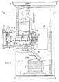
- the meat grinder 1 shown schematically in FIG. 1 essentially consists of a machine housing 2 with a filling bowl 3 releasably connected thereto, to which a filling shaft 4 is fastened.
- the feed chute 4 merges into a receiving bushing 5, which serves for the storage of a delivery housing 6.
- a screw conveyor 7 is rotatably arranged in the conveyor housing 6, a screw conveyor 7 is rotatably arranged.
- the screw conveyor 7 is driven by a drive motor 13 (shown in broken lines), a belt drive 14 and a gear 15, the gear 15 being fixedly connected to the receiving bush 5.
- the screw conveyor is driven by a plug-in coupling. This consists of a square shoulder 16 of the worm 7, which penetrates into a corresponding recess in a drive shaft 17 of the gear 15 designed as a hollow shaft.
- the conveyor housing 6 rests against a stop collar 18 of the receiving bush 5.
- the screw conveyor 7 has at its drive end a collar 19 which is arranged at a safety distance S with respect to a rear wall 20 of the conveyor housing 6.
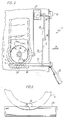
- the conveyor housing 6 is locked in the receiving bush 5 while maintaining the safety distance S by means of a locking shaft 21 which can be pivoted back and forth between an engagement and disengagement position via a lever 22 rigidly connected to it.
- the axis of rotation of the locking shaft 21 is perpendicular to the longitudinal axis of the receiving bush 5 and the conveyor housing 6, so that the shaft 21 tangentially cuts the at least partially circular-cylindrical components 5 and 6.
- the wall of the receiving bushing 5 and the conveying housing 6 each have tangential "half-bores" 45 and 24, which enclose the circular-cylindrical locking shaft 21.
- This in turn has - compare FIGS. 2 and 3 - a recess 23 in the area of these half-bores, which in the engaged position of the locking shaft 21 fixes the conveyor housing 6 in the receiving bush 5, depending on the disengaged position against insertion or extraction of the conveyor housing 6 with respect to the receiving bush 5.
- the recess 23 is adapted to the shape of the outer circumference of the conveyor housing 6 accordingly.
- the locking shaft 21 can be moved back and forth by the lever 22 between the engagement and disengagement position.
- a first locking segment 25 is connected in a rotationally fixed manner to the locking shaft 21.
- a conventional rotary switch 27 arranged on the machine housing 2 for switching the electric motor 13 on and off has a switching shaft 26 with a switching handle 29 arranged thereon.
- a second locking segment 28 is connected in a rotationally fixed manner to the switching shaft 26 and has a guide surface 30 curved concavely about the axis of rotation of the locking shaft 21 and an elongated leg 31.
- Two bolts 32 protrude from the first locking segment 25 towards the second locking segment 28 and are in abutment against the guide surface 30 in the disengaged position of the locking shaft 21.
- the bolts 32 act as stops and prevent the second blocking segment 28 and the rotary switch 27 from rotating, so that the motor 13 of the meat grinder 1 cannot be switched on. Only when the shaft 21 is pivoted into the engaged position and thereby the conveyor housing 6 is locked in the receiving bush 5 (shown in broken lines in FIG. 4) can the second locking segment and with it the rotary switch 27 be brought into the switched-on position (also shown in broken lines in FIG. 4) shown).
- the arrangement of the bolts 32 and the guide surface 30 is designed so that when the first locking segment 25 is pivoted back out of the moved into the engaged position, the second locking segment 28 and thus the rotary switch 27 are taken automatically and thereby the meat grinder 1 is switched off.
- the locking device according to FIGS. 1 to 4 thus provides double security in that it becomes effective both when the motor 13 is switched on and when the lock is released.
- the receiving bushing 5 and the conveying housing 6 are locked together by a displaceable bolt 34 which is prestressed by a spring 33, the bolt 34 being guided in the receiving bushing 5 and being able to penetrate into a corresponding recess 35 in the conveying housing 6.
- an eccentric disk 36 is arranged, by means of which the bolt 34 can be engaged and disengaged by pivoting the shaft 21.
- the embodiment according to FIG. 5 corresponds to the embodiment according to FIGS. 1 to 4.
- the locking shaft is designed as a screw spindle 38 which can be rotated in a screw thread of the receiving bushing 5 and can thus be moved axially back and forth with respect to this bushing.
- a rotary handle 37 is seated on one end of the screw spindle 38, the other end of the screw spindle is designed as a fixing pin 39 which, when the spindle 38 is rotated, penetrates into a corresponding recess 40 in the feed housing 6 and locks it with the receiving bush 5.
- the screw spindle 38 is seated and the selector shaft 26 each rotatably locking segments 41 and 42, the shape of which is best seen in Figure 7.
- the locking segment 41 (see FIG. 6) is axially displaced with respect to the locking segment 42, so that the locking segment 42 and thus the rotary switch 27 can be actuated without hindrance.
- the fixing pin 39 is not in engagement with the recess 40 and therefore the conveyor housing 6 is not locked with the receiving bush 5, the first locking segment 41 engages in a corresponding recess 44 in the second locking segment, so that it is blocked and the Rotary switch 27 can not be turned on (dash-dotted lines in Figure 7).
- FIGS. 6 and 7 is simplified compared to the embodiments according to FIGS. 1 to 5, because when the screw spindle 38 is moved from the engaged to the disengaged position, there is no inevitable return of the rotary switch 27 from the switch-on to the switch-off position.
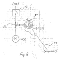
- FIG. 8 schematically shows a further embodiment of the invention.
- a switch cam 51 which interrupts the electrical current flow from the mains via a safety limit switch 52 and via the switch 27 to the motor 13 if the shaft 21 is not in the engagement position and the conveyor housing 6 is not fixed in position in the receiving socket 5 is. Switching on the motor 13 is therefore only possible with the conveyor housing 6 properly fixed.
- switch 27 can also in this embodiment a self-holding circuit with a switch protection can be used in a manner known per se.
Landscapes
- Engineering & Computer Science (AREA)
- Food Science & Technology (AREA)
- Crushing And Pulverization Processes (AREA)
- Meat, Egg Or Seafood Products (AREA)
Abstract
Description
- Die Erfindung betrifft einen Fleischwolf mit einem Gehäuse, einem im Gehäuse fest angeordneten Antriebsaggregat aus Motor und Getriebe, einem Drehschalter zum Ein- und Ausschalten des Motors, einer mit dem Getriebe fest verbundenen, einen Einfüllschacht aufweisenden Aufnahmebuchse, einem in die Aufnahmebuchse einführbaren Fördergehäuse, einer im Fördergehäuse drehbaren Förderschnecke, die an ihrem einen Ende mit dem Getriebe durch eine Steckkupplung verbunden ist, einem dem Fördergehäuse und der Förderschnecke zugeordneten Schneidsatz und einer ein- und ausrückbaren Verriegelungsvorrichtung zum lagegenauen Fixieren des Fördergehäuses in der Aufnahmebuchse.
- Bei Geräten dieser Art treten beim Vorzerkleinern des Schneidgutes mittels der Förderschnecke starke axiale Kräfte auf, welche die Förderschnecke entgegen und das Fördergehäuse in der Förderrichtung belasten. Die auf die Förderschnecke wirkenden Axialkräfte werden bei den bekannten Geräten von der Getriebewelle, die auf das Fördergehäuse wirkenden Axialkräfte werden von lösbaren Verriegelungselementen aufgenommen, wobei zwischen der stirnseitigen Innenfläche des Fördergehäuses und einem stirnseitigen Bund der Förderschnecke bei ordnungsgemäßem Zusammenbau des Fleischwolfes zur Vermeidung von Reibung und Abnutzung ein Sicherheitsabstand vorhanden ist.
- Beim Arbeiten mit nicht lagegenau und somit funktionsgerecht eingesetztem und verriegeltem Fördergehäuse kommt es durch die beschriebenen Axialkräfte zu einer Verschiebung des Fördergehäuses, die bis zum Anlaufen am stirnseitigen Bund der Förderschnecke führen kann. Dadurch entsteht hohe Reibungswärme, die zur Zerstörung des Fördergehäuses und der Förderschnecke führen kann.
- Es ist Aufgabe der Erfindung, diesem Mangel abzuhelfen und in einfacher Weise zu verhindern, daß der Fleischwolf bei nicht ordnungsgemäß eingesetztem und verriegeltem Fördergehäuse eingeschaltet werden kann.
- Die Aufgabe wird erfindungsgemäß dadurch gelöst, daß die Verriegelungsvorrichtung eine zwischen einer Ein- und einer Ausrückposition hin- und herbewegliche Verriegelungswelle umfaßt, die ein Einschalten des Motors nur in Einrückposition und bei lagegenauer Fixierung des Fördergehäuses in der Aufnahmebuchse gestattet.
- Die nachstehende Beschreibung bevorzugter Ausführungsformen der Erfindung dient im Zusammenhang mit beiliegender Zeichnung der weiteren Erläuterung. Es zeigen:
- - Figur 1 eine teilweise aufgebrochene Seitenansicht eines Fleischwolfes;
- - Figur 2 eine Teilschnittansicht entlang der Linie 2-2 in Figur 1;
- - Figur 3 eine Einzelheit einer Verriegelungswelle aus Figur 2;
- - Figur 4 eine Einzeldarstellung in Richtung des Pfeiles A in Figur 2;
- - Figur 5 eine Schnittansicht ähnlich Figur 2 einer abgewandelten Ausführungsform;
- - Figur 6 eine Schnittansicht ähnlich Figur 5 einer weiterhin abgewandelten Ausführungsform;
- - Figur 7 eine Einzeldarstellung in Richtung des Pfeiles B in Figur 6, und
- - Figur 8 eine schematische Darstellung einer abgewandelten Ausführungsform.
- Der in Figur 1 schematisch dargestellte Fleischwolf 1 besteht im wesentlichen aus einem Maschinengehäuse 2 mit damit lösbar verbundener Einfüllschale 3, an der ein Einfüllschacht 4 befestigt ist. Der Einfüllschacht 4 geht in eine Aufnahmebuchse 5 über, die der Lagerung eines Fördergehäuses 6 dient. Im Fördergehäuse 6 ist eine Förderschnecke 7 drehbar angeordnet. Ein dem Fördergehäuse 6 und der Förderschnecke 7 in an sich bekannter Weise zugeordneter, vorzugsweise mindestens zweiteiliger Schneidsatz 8 umfaßt zwei im Gehäuse 6 fixierte Lochscheiben 9 und ein mit der Schnecke 7 drehfest verbundenes Flügelmesser 10. Der Schneidsatz ist durch eine Überwurfmutter 11 und einen Spannring 12 spielfrei im Fördergehäuse 6 fixiert.
- Die Förderschnecke 7 wird über einen (strichpunktiert dargestellten) Antriebsmotor 13, einen Riementrieb 14 und ein Getriebe 15 angetrieben, wobei das Getriebe 15 mit der Aufnahmebuchse 5 fest verbunden ist. Die drehende Mitnahme der Förderschnecke erfolgt über eine Steckkupplung. Diese besteht aus einem Vierkantansatz 16 der Schnecke 7, der in eine entsprechende Aussparung einer als Hohlwelle ausgebildeten Antriebswelle 17 des Getriebes 15 eindringt.
- In ordnungsgemäßem, d. h. lagegenau und funktionsgerecht zusammengebautem Zustand liegt das Fördergehäuse 6 an einem Anschlagbund 18 der Aufnahmebuchse 5 an. Die Förderschnecke 7 weist an ihrem antriebsseitigen Ende einen Bund 19 auf, der mit Bezug auf eine Rückwand 20 des Fördergehäuses 6 in einem Sicherheitsabstand S angeordnet ist. Die Verriegelung des Fördergehäuses 6 in der Aufnahmebuchse 5 erfolgt unter Einhaltung des Sicherheitsabstandes S durch eine Verriegelungswelle 21, die über einen starr mit ihr verbundenen Hebel 22 zwischen einer Ein- und Ausrückposition hin- und herverschwenkbar ist. Die Drehachse der Verriegelungswelle 21 verläuft senkrecht zur Längsachse der Aufnahmebuchse 5 und des Fördergehäuses 6, so daß die Welle 21 die zumindest teilweise kreiszylindrisch ausgebildeten Bauteile 5 und 6 tangential schneidet. Hierzu weist die Wand von Aufnahmebuchse 5 und Fördergehäuse 6 jeweils tangential verlaufende "Halbbohrungen" 45 bzw. 24 auf, welche die kreiszylindrisch ausgebildete Verriegelungswelle 21 umschließen. Diese weist ihrerseits - vergleiche Figur 2 und 3 - im Bereich dieser Halbbohrungen eine Aussparung 23 auf, welche in der eingerückten Position der Verriegelungswelle 21 das Fördergehäuse 6 in der Aufnahmebuchse 5 fixiert, in der ausgerückten Position hinge gegen ein Einführen oder Herausziehen des Fördergehäuses 6 bezüglich der Aufnahmebuchse 5 ermöglicht. Die Aussparung 23 ist dabei an die Form des Außenumfangs des Fördergehäuses 6 entsprechend angepaßt. Die Verriegelungswelle 21 kann durch den Hebel 22 zwischen der Ein- und Ausrückposition hin- und herverstellt werden.
- Mit der Verriegelungswelle 21 ist drehfest ein erstes Sperrsegment 25 verbunden. Ein üblicher, am Maschinengehäuse 2 angeordneter Drehschalter 27 zum Ein- und Ausschalten des Elektromotors 13 weist eine Schaltwelle 26 mit darauf angeordnetem Schaltgriff 29 auf. Mit der Schaltwelle 26 ist drehfest ein zweites Sperrsegment 28 verbunden, das eine konkav um die Drehachse der Verriegelungswelle 21 gekrümmte Führungsfläche 30 und einen verlängerten Schenkel 31 aufweist. Vom ersten Sperrsegment 25 stehen zum zweiten Sperrsegment 28 hin zwei Bolzen 32 ab, die sich in der ausgerückten Stellung der Verriegelungswelle 21 in Anlage an der Führungsfläche 30 befinden. In dieser Stellung wirken die Bolzen 32 als Anschläge und verhindern ein Verdrehen des zweiten Sperrsegments 28 und des Drehschalters 27, so daß der Motor 13 des Fleischwolfes 1 nicht eingeschaltet werden kann. Erst wenn die Welle 21 in die eingerückte Stellung verschwenkt und hierdurch das Fördergehäuse 6 in der Aufnahmebuchse 5 verriegelt ist (in Figur 4 strichpunktiert dargestellt), können das zweite Sperrsegment und mit ihm der Drehschalter 27 in die Einschaltstellung gebracht werden (in Figur 4 ebenfalls strichpunktiert dargestellt).
- Wie sich aus Figur 4 ergibt, ist die Anordnung der Bolzen 32 und die Führungsfläche 30 so gestaltet, daß bei einem Zurückverschwenken des ersten Sperrsegments 25 aus der ausge rückten in die eingerückte Position das zweite Sperrsegment 28 und damit der Drehschalter 27 automatisch mitgenommen werden und hierdurch der Fleischwolf 1 ausgeschaltet wird. Die Verriegelungsvorrichtung gemäß Figur 1 bis 4 vermittelt also insoweit eine doppelte Sicherheit, indem sie sowohl beim Einschalten des Motors 13 als auch bei der Aufhebung der Verriegelung wirksam wird.
- Bei der Ausführungsform gemäß Figur 5 werden Aufnahmebuchse 5 und Fördergehäuse 6 durch einen verschieblichen und von einer Feder 33 vorgespannten Bolzen 34 miteinander verriegelt, wobei der Bolzen 34 in der Aufnahmebuchse 5 geführt und in eine entsprechende Ausnehmung 35 des Fördergehäuses 6 eindringen kann. Am freien Ende der Verriegelungswelle 21 ist eine Exzenterscheibe 36 angeordnet, mit deren Hilfe der Bolzen 34 durch Verschwenken der Welle 21 ein- und ausgerückt werden kann. Im übrigen entspricht die Ausführungsform gemäß Figur 5 der Ausführungsform gemäß Figur 1 bis 4.
- Bei einer weiterhin abgewandelten Ausführungsform gemäß Figur 6 und 7 ist die Verriegelungswelle als Schraubspindel 38 ausgebildet, die in einem Schraubgewinde der Aufnahmebuchse 5 verdrehbar und hierdurch mit Bezug auf diese Buchse axial hin- und herbeweglich ist. Auf dem einen Ende der Schraubspindel 38 sitzt ein Drehgriff 37, das andere Ende der Schraubspindel ist als Fixierzapfen 39 ausgebildet, der beim Verdrehen der Spindel 38 in eine entsprechende Ausnehmung 40 des Fördergehäuses 6 eindringt und dieses mit der Aufnahmebuchse 5 verriegelt.
- Bei dieser Ausführungsform sitzen auf der Schraubspindel 38 und der Schaltwelle 26 jeweils drehfest Sperrsegmente 41 bzw. 42, deren Form am besten aus Figur 7 ersichtlich ist. In der eingerückten oder Verriegelungsposition ist das Sperrsegment 41 (vergleiche Figur 6) gegenüber dem Sperrsegment 42 axial verschoben, so daß das Sperrsegment 42 und damit der Drehschalter 27 ungehindert betätigt werden können. Ist hingegen bei ausgeschaltetem Drehschalter 27 der Fixierzapfen 39 nicht in Eingriff mit der Ausnehmung 40 und daher das Fördergehäuse 6 mit der Aufnahmebuchse 5 nicht verriegelt, greift das erste Sperrsegment 41 in eine entsprechende Aussparung 44 des zweiten Sperrsegments ein, so daß dieses blockiert ist und der Drehschalter 27 nicht eingeschaltet werden kann (strichpuntierte Linien in Figur 7).
- Die Ausführungsform gemäß Figur 6 und 7 ist gegenüber den Ausführungsformen nach Figur 1 bis 5 vereinfacht, weil beim Verstellen der Schraubspindel 38 von der eingerückten in die ausgerückte Position keine zwangsläufige Rückführung des Drehschalters 27 von der Einschalt- in die Ausschaltstellung stattfindet.
- Die Figur 8 zeigt schematisch eine weitere Ausführungsform der Erfindung. Auf der Verriegelungswelle 27 sitzt ein Schaltnocken 51, der über einen Sicherheits-Endschalter 52 den elektrischen Stromfluß aus dem Netz und über den Schalter 27 zum Motor 13 unterbricht, wenn die Welle 21 nicht in Einrückposition und das Fördergehäuse 6 nicht lagegenau in der Aufnahmebuchse 5 fixiert ist. Ein Einschalten des Motors 13 ist somit nur bei ordnungsgemäßer Fixierung des Fördergehäuses 6 möglich.
- Statt dem Schalter 27 kann bei dieser Ausführungsform auch in an sich bekannter Weise eine Selbsthalteschaltung mit einem Schaltschutz Anwendung finden.
- Bei der Ausführungsform nach Figur 8 entfallen die mechanischen Sperrsegmente 25 und 41 bzw. 28 and 42.
Claims (9)
Priority Applications (1)
| Application Number | Priority Date | Filing Date | Title |
|---|---|---|---|
| AT88112983T ATE96056T1 (de) | 1987-08-20 | 1988-08-10 | Fleischwolf. |
Applications Claiming Priority (2)
| Application Number | Priority Date | Filing Date | Title |
|---|---|---|---|
| DE3727751 | 1987-08-20 | ||
| DE19873727751 DE3727751A1 (de) | 1987-08-20 | 1987-08-20 | Fleischwolf |
Publications (3)
| Publication Number | Publication Date |
|---|---|
| EP0303956A2 true EP0303956A2 (de) | 1989-02-22 |
| EP0303956A3 EP0303956A3 (en) | 1990-01-17 |
| EP0303956B1 EP0303956B1 (de) | 1993-10-20 |
Family
ID=6334113
Family Applications (1)
| Application Number | Title | Priority Date | Filing Date |
|---|---|---|---|
| EP88112983A Expired - Lifetime EP0303956B1 (de) | 1987-08-20 | 1988-08-10 | Fleischwolf |
Country Status (3)
| Country | Link |
|---|---|
| EP (1) | EP0303956B1 (de) |
| AT (1) | ATE96056T1 (de) |
| DE (2) | DE3727751A1 (de) |
Cited By (4)
| Publication number | Priority date | Publication date | Assignee | Title |
|---|---|---|---|---|
| EP0695581A1 (de) * | 1994-08-04 | 1996-02-07 | Braun Aktiengesellschaft | Fleischwolf |
| EP1832346A3 (de) * | 2006-03-07 | 2009-03-11 | La Minerva Di Chiodini Mario S.R.L. | Sicherheitsvorrichtung für Fleischwölfe und ähnliches |
| ITVI20100352A1 (it) * | 2010-12-28 | 2012-06-29 | Felsinea S R L | Dispositivo automatizzato di sicurezza per tritacarne |
| ITBO20110463A1 (it) * | 2011-07-29 | 2013-01-30 | Essedue S R L | Dispositivo di sicurezza per tritacarne o simili. |
Family Cites Families (6)
| Publication number | Priority date | Publication date | Assignee | Title |
|---|---|---|---|---|
| DE450116C (de) * | 1926-11-13 | 1927-09-29 | Wommer Maschinenfabrik Geb | Ein-, Ausschalt- und Ausstossvorrichtung bei Fleischwoelfen |
| DE923952C (de) * | 1953-03-08 | 1955-02-24 | Krauss Maffei Ag | Fleischwolf mit Drehstromantrieb |
| DE8320586U1 (de) * | 1983-07-16 | 1983-12-22 | Samix-Umwelttechnik-Maschinenbau GmbH, 6330 Kufstein | Vorrichtung zum zerkleinern von haeckselgut |
| DE3503718A1 (de) * | 1985-02-04 | 1985-07-25 | Bosch-Siemens Hausgeräte GmbH, 7000 Stuttgart | Elektrische kuechenmaschine |
| DE8526418U1 (de) * | 1985-09-16 | 1986-02-13 | Robert Stahlschmidt RST Motorenwerk GmbH, 4800 Bielefeld | Gerät mit umlaufendem Werkzeug |
| DE8526857U1 (de) * | 1985-09-19 | 1985-10-31 | Atika-Maschinenfabrik Wilhelm Pollmeier GmbH & Co, 4730 Ahlen | Gartenhäcksler |
-
1987
- 1987-08-20 DE DE19873727751 patent/DE3727751A1/de not_active Withdrawn
-
1988
- 1988-08-10 DE DE88112983T patent/DE3885039D1/de not_active Expired - Fee Related
- 1988-08-10 AT AT88112983T patent/ATE96056T1/de not_active IP Right Cessation
- 1988-08-10 EP EP88112983A patent/EP0303956B1/de not_active Expired - Lifetime
Cited By (5)
| Publication number | Priority date | Publication date | Assignee | Title |
|---|---|---|---|---|
| EP0695581A1 (de) * | 1994-08-04 | 1996-02-07 | Braun Aktiengesellschaft | Fleischwolf |
| EP1832346A3 (de) * | 2006-03-07 | 2009-03-11 | La Minerva Di Chiodini Mario S.R.L. | Sicherheitsvorrichtung für Fleischwölfe und ähnliches |
| ITVI20100352A1 (it) * | 2010-12-28 | 2012-06-29 | Felsinea S R L | Dispositivo automatizzato di sicurezza per tritacarne |
| EP2471601A1 (de) * | 2010-12-28 | 2012-07-04 | La Felsinea S.r.L. | Automatisierte Sicherheitsvorrichtung für Zerkleinerungsmaschinen |
| ITBO20110463A1 (it) * | 2011-07-29 | 2013-01-30 | Essedue S R L | Dispositivo di sicurezza per tritacarne o simili. |
Also Published As
| Publication number | Publication date |
|---|---|
| EP0303956B1 (de) | 1993-10-20 |
| DE3885039D1 (de) | 1993-11-25 |
| DE3727751A1 (de) | 1989-03-02 |
| ATE96056T1 (de) | 1993-11-15 |
| EP0303956A3 (en) | 1990-01-17 |
Similar Documents
| Publication | Publication Date | Title |
|---|---|---|
| DE69409134T2 (de) | Halterungssystem für ein Sägeblatt | |
| EP0650805B1 (de) | Elektrowerkzeug | |
| EP0401548B1 (de) | Schraubwerkzeugmaschine | |
| DE3741484C1 (de) | Handwerkzeugmaschine mit automatischer Arretierung der Arbeitsspindel | |
| EP0023951B1 (de) | Motorgetriebenes Handwerkzeug, insbesondere Heimwerkerkombinationsmaschine | |
| DE2613065C3 (de) | Automatische Kupplungsvorrichtung für ein Handrad | |
| EP0716896A1 (de) | Bohrvorrichtung | |
| EP1092379B1 (de) | Elektrisch betriebener Handrührer | |
| DE69218823T2 (de) | Lageeinstell- und Begrenzungsvorrichtung für ein zentrifugales Betätigungselement eines Elektromotors | |
| DE102014116705B4 (de) | Laborrührer | |
| EP1572403B1 (de) | Kraftspannfutter und keilstange dafür | |
| EP0458170A2 (de) | Spannfutter | |
| DE2904535C2 (de) | Drehantrieb für eine Schneidvorrichtung zum Zerkleinern von Nahrungsmitteln | |
| EP0303956B1 (de) | Fleischwolf | |
| DE3305632C2 (de) | Reibungskupplungs- und Bremskombination | |
| EP0237857B1 (de) | Antriebsvorrichtung für einen elektrischen Trennschalter | |
| EP0054912B1 (de) | Vorrichtung, insbes. tragbare Vorrichtung, zum Bearbeiten von rohr und/oder stangenförmigen Werkstücken oder dergleichen | |
| DE29502032U1 (de) | Preßwerkzeug | |
| DE2755401A1 (de) | Anordnung zum absenken der leerlaufdrehzahl eines elektromotors | |
| EP0095572A1 (de) | Drehrichtungssperre für den Rotor eines Synchronmotors | |
| DE102016015728B4 (de) | Parksperren-Aktuatoreinheit | |
| DE4208474C2 (de) | Handrad-Stellvorrichtung für Offset-Druckmaschinen | |
| DE1654887C3 (de) | Werkzeug-Auswerfvorrichtung für eine elektrische Küchenmaschine, insbesondere einen Handquirl | |
| DE1009886B (de) | Handrad fuer die Feinverstellung der Schlitten von Werkzeugmaschinen, insbesondere Fraesmaschinen | |
| EP4480650B1 (de) | Fleisch-trimmer, kupplungsanordnung hierfür sowie verwendung derselben |
Legal Events
| Date | Code | Title | Description |
|---|---|---|---|
| PUAI | Public reference made under article 153(3) epc to a published international application that has entered the european phase |
Free format text: ORIGINAL CODE: 0009012 |
|
| AK | Designated contracting states |
Kind code of ref document: A2 Designated state(s): AT DE FR GB |
|
| PUAL | Search report despatched |
Free format text: ORIGINAL CODE: 0009013 |
|
| AK | Designated contracting states |
Kind code of ref document: A3 Designated state(s): AT DE FR GB |
|
| 17P | Request for examination filed |
Effective date: 19900628 |
|
| 17Q | First examination report despatched |
Effective date: 19910822 |
|
| GRAA | (expected) grant |
Free format text: ORIGINAL CODE: 0009210 |
|
| AK | Designated contracting states |
Kind code of ref document: B1 Designated state(s): AT DE FR GB |
|
| REF | Corresponds to: |
Ref document number: 96056 Country of ref document: AT Date of ref document: 19931115 Kind code of ref document: T |
|
| REF | Corresponds to: |
Ref document number: 3885039 Country of ref document: DE Date of ref document: 19931125 |
|
| GBT | Gb: translation of ep patent filed (gb section 77(6)(a)/1977) |
Effective date: 19931109 |
|
| ET | Fr: translation filed | ||
| PLBE | No opposition filed within time limit |
Free format text: ORIGINAL CODE: 0009261 |
|
| STAA | Information on the status of an ep patent application or granted ep patent |
Free format text: STATUS: NO OPPOSITION FILED WITHIN TIME LIMIT |
|
| 26N | No opposition filed | ||
| PGFP | Annual fee paid to national office [announced via postgrant information from national office to epo] |
Ref country code: FR Payment date: 20010801 Year of fee payment: 14 |
|
| PGFP | Annual fee paid to national office [announced via postgrant information from national office to epo] |
Ref country code: GB Payment date: 20010810 Year of fee payment: 14 |
|
| PGFP | Annual fee paid to national office [announced via postgrant information from national office to epo] |
Ref country code: AT Payment date: 20010818 Year of fee payment: 14 |
|
| PGFP | Annual fee paid to national office [announced via postgrant information from national office to epo] |
Ref country code: DE Payment date: 20010924 Year of fee payment: 14 |
|
| REG | Reference to a national code |
Ref country code: GB Ref legal event code: IF02 |
|
| PG25 | Lapsed in a contracting state [announced via postgrant information from national office to epo] |
Ref country code: GB Free format text: LAPSE BECAUSE OF NON-PAYMENT OF DUE FEES Effective date: 20020810 Ref country code: AT Free format text: LAPSE BECAUSE OF NON-PAYMENT OF DUE FEES Effective date: 20020810 |
|
| PG25 | Lapsed in a contracting state [announced via postgrant information from national office to epo] |
Ref country code: DE Free format text: LAPSE BECAUSE OF NON-PAYMENT OF DUE FEES Effective date: 20030301 |
|
| GBPC | Gb: european patent ceased through non-payment of renewal fee |
Effective date: 20020810 |
|
| PG25 | Lapsed in a contracting state [announced via postgrant information from national office to epo] |
Ref country code: FR Free format text: LAPSE BECAUSE OF NON-PAYMENT OF DUE FEES Effective date: 20030430 |
|
| REG | Reference to a national code |
Ref country code: FR Ref legal event code: ST |