EP0303944A1 - Verfahren und Schaltung zur Anregung eines Ultraschallschwingers, und deren Verwendung zur Zerstäubung einer Flüssigkeit - Google Patents
Verfahren und Schaltung zur Anregung eines Ultraschallschwingers, und deren Verwendung zur Zerstäubung einer Flüssigkeit Download PDFInfo
- Publication number
- EP0303944A1 EP0303944A1 EP88112934A EP88112934A EP0303944A1 EP 0303944 A1 EP0303944 A1 EP 0303944A1 EP 88112934 A EP88112934 A EP 88112934A EP 88112934 A EP88112934 A EP 88112934A EP 0303944 A1 EP0303944 A1 EP 0303944A1
- Authority
- EP
- European Patent Office
- Prior art keywords
- oscillator
- frequency
- voltage
- control
- ultrasonic
- Prior art date
- Legal status (The legal status is an assumption and is not a legal conclusion. Google has not performed a legal analysis and makes no representation as to the accuracy of the status listed.)
- Withdrawn
Links
- 230000005284 excitation Effects 0.000 title claims abstract description 29
- 239000007788 liquid Substances 0.000 title claims abstract description 6
- 238000000034 method Methods 0.000 title claims description 13
- 238000000889 atomisation Methods 0.000 title abstract description 9
- 230000010355 oscillation Effects 0.000 claims abstract description 12
- 230000000737 periodic effect Effects 0.000 claims 1
- 239000002002 slurry Substances 0.000 claims 1
- 239000003990 capacitor Substances 0.000 description 15
- 238000010586 diagram Methods 0.000 description 3
- 238000005259 measurement Methods 0.000 description 3
- 238000001514 detection method Methods 0.000 description 2
- 238000009688 liquid atomisation Methods 0.000 description 2
- 238000004519 manufacturing process Methods 0.000 description 2
- 238000004804 winding Methods 0.000 description 2
- 230000032683 aging Effects 0.000 description 1
- 230000007423 decrease Effects 0.000 description 1
- 230000001419 dependent effect Effects 0.000 description 1
- 238000011161 development Methods 0.000 description 1
- 230000018109 developmental process Effects 0.000 description 1
- 230000003993 interaction Effects 0.000 description 1
- 229920005989 resin Polymers 0.000 description 1
- 239000011347 resin Substances 0.000 description 1
- 238000000926 separation method Methods 0.000 description 1
- 239000004071 soot Substances 0.000 description 1
- 239000000725 suspension Substances 0.000 description 1
- 238000002604 ultrasonography Methods 0.000 description 1
Images
Classifications
-
- B—PERFORMING OPERATIONS; TRANSPORTING
- B05—SPRAYING OR ATOMISING IN GENERAL; APPLYING FLUENT MATERIALS TO SURFACES, IN GENERAL
- B05B—SPRAYING APPARATUS; ATOMISING APPARATUS; NOZZLES
- B05B17/00—Apparatus for spraying or atomising liquids or other fluent materials, not covered by the preceding groups
- B05B17/04—Apparatus for spraying or atomising liquids or other fluent materials, not covered by the preceding groups operating with special methods
- B05B17/06—Apparatus for spraying or atomising liquids or other fluent materials, not covered by the preceding groups operating with special methods using ultrasonic or other kinds of vibrations
- B05B17/0607—Apparatus for spraying or atomising liquids or other fluent materials, not covered by the preceding groups operating with special methods using ultrasonic or other kinds of vibrations generated by electrical means, e.g. piezoelectric transducers
- B05B17/0653—Details
- B05B17/0669—Excitation frequencies
-
- B—PERFORMING OPERATIONS; TRANSPORTING
- B05—SPRAYING OR ATOMISING IN GENERAL; APPLYING FLUENT MATERIALS TO SURFACES, IN GENERAL
- B05B—SPRAYING APPARATUS; ATOMISING APPARATUS; NOZZLES
- B05B17/00—Apparatus for spraying or atomising liquids or other fluent materials, not covered by the preceding groups
- B05B17/04—Apparatus for spraying or atomising liquids or other fluent materials, not covered by the preceding groups operating with special methods
- B05B17/06—Apparatus for spraying or atomising liquids or other fluent materials, not covered by the preceding groups operating with special methods using ultrasonic or other kinds of vibrations
- B05B17/0607—Apparatus for spraying or atomising liquids or other fluent materials, not covered by the preceding groups operating with special methods using ultrasonic or other kinds of vibrations generated by electrical means, e.g. piezoelectric transducers
-
- B—PERFORMING OPERATIONS; TRANSPORTING
- B06—GENERATING OR TRANSMITTING MECHANICAL VIBRATIONS IN GENERAL
- B06B—METHODS OR APPARATUS FOR GENERATING OR TRANSMITTING MECHANICAL VIBRATIONS OF INFRASONIC, SONIC, OR ULTRASONIC FREQUENCY, e.g. FOR PERFORMING MECHANICAL WORK IN GENERAL
- B06B1/00—Methods or apparatus for generating mechanical vibrations of infrasonic, sonic, or ultrasonic frequency
- B06B1/02—Methods or apparatus for generating mechanical vibrations of infrasonic, sonic, or ultrasonic frequency making use of electrical energy
- B06B1/0207—Driving circuits
- B06B1/0223—Driving circuits for generating signals continuous in time
- B06B1/0238—Driving circuits for generating signals continuous in time of a single frequency, e.g. a sine-wave
- B06B1/0246—Driving circuits for generating signals continuous in time of a single frequency, e.g. a sine-wave with a feedback signal
- B06B1/0253—Driving circuits for generating signals continuous in time of a single frequency, e.g. a sine-wave with a feedback signal taken directly from the generator circuit
-
- B—PERFORMING OPERATIONS; TRANSPORTING
- B06—GENERATING OR TRANSMITTING MECHANICAL VIBRATIONS IN GENERAL
- B06B—METHODS OR APPARATUS FOR GENERATING OR TRANSMITTING MECHANICAL VIBRATIONS OF INFRASONIC, SONIC, OR ULTRASONIC FREQUENCY, e.g. FOR PERFORMING MECHANICAL WORK IN GENERAL
- B06B2201/00—Indexing scheme associated with B06B1/0207 for details covered by B06B1/0207 but not provided for in any of its subgroups
- B06B2201/70—Specific application
- B06B2201/77—Atomizers
Definitions
- the invention relates to a method and a circuit for excitation of an ultrasonic vibrator and their use for atomizing a liquid.
- Such parameters are, for example, the manufacturing tolerances of the mechanical components of the ultrasonic vibrator (in particular its atomizing plate), the variations in the mechanical and electrical parameters of its origin Position used piezoceramic, the operating temperature of the ultrasonic transducer (very important when used in burners), the aging of the ultrasonic transducer, the deposits that form on it (such as soot and resins when used in burners), and also the manufacturing, adjustment and other tolerances in the excitation circuit.
- the reliable detection of atomization suspension must be guaranteed.
- the ability to atomize the ultrasonic vibrator or its atomizing plate must be able to regulate itself without any intervention by an operator and e.g. the excitation voltage or the duty cycle of the control frequency must change.
- DE-3222425 it was proposed to excite the ultrasonic vibrator via a matching network which, among other things, is intended to suppress the oscillation of the ultrasonic vibrator at harmonics of its resonance frequency.
- the DC component of the resonator current is used to regulate the excitation current and the AC component of the Re sonator current is used to regulate the excitation frequency, with a bandpass only passing the frequency component at the desired resonance frequency of the ultrasonic oscillator. If the resonance fails, the excitation frequency is swept in order to pass through the resonance point and to achieve re-engagement.
- the disadvantage of this solution is that the circuit is matched to the ultrasonic oscillator and in particular to its resonance target frequency, so that the operation of the ultrasonic oscillator cannot be tracked to the changes in some of the parameters listed above and the easy interchangeability of components with spare parts does not guarantee is.
- a reliable function is not guaranteed when starting up, especially under load and with changing operating conditions, since the impedance and thus the phase relationships between the current and voltage of the ultrasonic transducer change significantly with changes in load, and thus a tracking of the optimal oscillation frequency, derived from the phase relationships between current and Voltage in the ultrasonic transducer is not possible. It is not possible to achieve a real compensation of the capacitance of the ultrasonic vibrator by means of an inductor, because of the capacitance changing with changes in load.
- the object of the invention is to overcome the disadvantages mentioned above in a cost-effective manner.
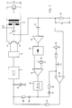
- the circuit for excitation of an ultrasonic oscillator shown in FIG. 1 comprises an ultrasonic oscillator 1, the atomizing plate of which is known per se is not shown.
- the ultrasonic vibrator 1 is via a transformer 2 excited, which ensures a galvanic separation of the ultrasonic vibrator 1 and possibly (depending on its winding conditions) allows the excitation with different voltage values of the voltage source U.
- Two transistors 4 and 5 form a push-pull output stage of the circuit, they mutually switch the voltage source U through to one half of the primary winding of the transformer 2.
- the excitation circuit is closed via a current measuring resistor 18.
- a capacitor 3 leads the current changes directly from the transistors 4 and 5 back to the voltage source U and thereby causes the voltage drop V occurring at the current measuring resistor 18 to have a direct voltage component which is proportional to the direct current consumption of the output stage.
- a driver stage 6 supplies the necessary in-phase signals for the transistors 4 and 5.
- the voltage-controlled oscillator 7 generates the frequency f with which the ultrasonic vibrator 1 is excited.
- the DC voltage drop across the resistor 18 is a direct measure of the active power consumed by the ultrasonic vibrator 1. This, in turn, is a useful measure of atomization performance.
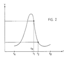
- FIG. 2 shows the profile of the DC voltage component, that is to say the time average of the voltage V across the current measuring resistor 18, that is to say also the profile of the active power consumed by the ultrasonic oscillator 1, as a function of the oscillation frequency f of the ultrasonic oscillator 1.
- the characteristic curve shown in FIG. 2 corresponds entirely to the well-known impedance curve (or reactance ver a resonance system like that of a piezo oscillator.
- the maximum recognizable in FIG. 2 corresponds to the series resonance resulting from the known equivalent circuit diagram of an oscillator, the recognizable minimum corresponds to the parallel resonance resulting from the same equivalent circuit diagram.
- the oscillator 7 in FIG. 1 is a voltage-controlled oscillator constructed using commercially available components.
- the permissible voltage swing at its control input is predetermined, the corresponding frequency swing at its frequency output can be adjusted in a known manner by the value of resistors and / or capacitors that are not shown in FIG. 1 and can be connected to the oscillator 7.
- the voltage V tapped at the current measuring resistor 18 is compared with a voltage in the comparator 21 that can be set on a potentiometer 19.
- the output signal of the comparator 21 is smoothed with the RC element formed from a resistor 9 and a capacitor 8 and supplied to the oscillator 7 as a control voltage.
- a defined operating point can thus be set and recorded on an edge of the characteristic curve in FIG. 2.
- the oscillator 7, the driver stage 6, the transistors 4 and 5, the capacitor 3, the transformer 2, the resistor 18, the comparator 21, the resistor 9 and the capacitor 8 form namely, together a controller, and together with this controller, a controlled system, which is given by the ultrasonic vibrator 1, forms a control loop.
- the oscillator 7 is now set such that with the control voltage swing at its control input (also at the capacitor 8) that can be generated by the comparator 21, only frequencies between f A and f B , that is to say only in a narrow range around the series resonance and the parallel resonance be generated. It is even better if the frequencies that can be generated are in a range that is within the range between the series resonance and the parallel resonance and is significantly smaller, such as the range between f 1 and f 2.
- the locking of the generator circuit to additional resonances which can result from a coordination between the transformer 2 and the ultrasonic vibrator 1 and which do not lead to an effective atomization, is thus ruled out.
- a special coordination between the transformer 2 and the ultrasonic oscillator 1 is therefore neither necessary nor desirable, and the effort for a filter in a resonance detection circuit is therefore also unnecessary.
- the large gain factor at the comparator 21 results in a two-point control in connection with the control voltage swing that can be generated thereby.
- This causes the ultrasonic vibrator 1 to be operated only at a frequency that corresponds to a predetermined target active power consumption.
- the operation of the ultrasonic vibrator 1 is possible due to the two-point control characteristic only at one of the two frequencies that correspond to the target active power consumption (e.g. on the higher-frequency flank of the characteristic curve shown in FIG. 2 and at the frequency f 1).
- control loop defined above is now designed so that defined control vibrations occur. This will be in the essentially achieved in that the control voltage swing generated by the comparator 21 is only incompletely smoothed by the RC element formed from the resistor 9 and the capacitor 8.
- the corresponding control oscillations which are expressed in a wobble of the excitation frequency and the oscillation frequency f of the ultrasonic oscillator 1 and consequently in an alternating voltage component superimposed on the direct voltage component, in the voltage drop V occurring at the current measuring resistor 18, are due to the interaction of the aforementioned resistor 9 and the capacitor 8 formed RC element with the current measuring resistor 18 and the capacitor 3 and with the gain factor on the comparator 21 and the active power characteristic of the ultrasonic transducer 1.
- control vibrations can only occur if the ultrasonic vibrator 1 has the characteristic curve shown in FIG. 2. This is only the case if it is atomized properly. If it is dampened too much by droplets that get stuck, it cannot show any pronounced resonance behavior according to the characteristic curve shown in FIG. 2 and the control vibrations do not occur or only occur very weakly and irregularly.
- control vibrations of the control loop can therefore be taken as a reliable criterion for proper atomization.
- the AC voltage component in the voltage drop V occurring at the current measuring resistor 18 is decoupled by a capacitor 17 and amplified by an amplifier 16.
- a rectifier 15 supplies a DC voltage as a measure of the amplitude of the amplified control vibrations.
- a comparator 13 decides, by comparing this DC voltage with a target voltage that can be set by a potentiometer 14, whether the control vibrations are sufficiently large.
- an oscillator 12 which in the present example is a rectangular oscillator, is started, so that a higher and a lower voltage alternately appear at its output. However, if the control oscillations are sufficiently large, the oscillator 12 is or remains switched off and decoupled from the control circuit by diodes 10 and 11.
- the control voltage at the control input of the oscillator 7 (and therefore also at the capacitor 8) is increased via the diode 10 and the resistor 30, so that the oscillator 7 after the resistor 9, the resistor 30 and the capacitor 8 given the time constant generates the upper limit frequency f B.
- the target current requirement at the input of the comparator 21 is increased via a diode 11 and a resistor 31. An operating point of the ultrasonic vibrator 1 is thus forced in the upper region of the characteristic curve shown in FIG. 2.
- the lower voltage subsequently appears at the output of the oscillator 12, it is decoupled from the control circuit via the diodes 10 and 11.
- the capacitor 8 discharges through the resistor 9 because the target voltage at the comparator 21 is higher than the actual voltage at this point in time and therefore the comparator output carries the lower output voltage (the target voltage is at the inverting input). Consequently, the frequency generated by the oscillator 7 decreases from f B in the direction f A.
- the period of the oscillator 12 is chosen large enough in relation to the time constant of the discharge of the capacitor 8 to ensure that the full frequency range between f B and f A is passed through.
- a power control on the ultrasonic oscillator 1 takes place in that the oscillation frequency f of the ultrasonic oscillator 1 defined by the excitation frequency is shifted between the series resonance and the parallel resonance.
- the smallest atomizing power is achieved with excitation in parallel resonance (large reactive power, low active power), the largest atomizing power with series resonance (small reactive power, large active power). Neither the excitation voltage nor the duty cycle need to be changed for power control.
- the invention has been described in connection with an ultrasonic oscillator, in particular a piezoelectric ultrasonic oscillator, the use of which, e.g. lies in the liquid atomization.
- the invention is also applicable to other resonance systems, the resonance of which takes place in a narrow frequency band and changes greatly as a function of a physical variable, this variable being intended to be maintained as precisely as possible.
- the invention is therefore generally suitable for keeping a physical variable constant by means of a control circuit which comprises a resonant body, the resonance behavior of which is strongly influenced by the physical variable in a narrow frequency band and is used to detect the changes thereof.
Landscapes
- Engineering & Computer Science (AREA)
- Mechanical Engineering (AREA)
- Special Spraying Apparatus (AREA)
- Apparatuses For Generation Of Mechanical Vibrations (AREA)
Applications Claiming Priority (2)
| Application Number | Priority Date | Filing Date | Title |
|---|---|---|---|
| CH3155/87 | 1987-08-17 | ||
| CH315587 | 1987-08-17 |
Publications (1)
| Publication Number | Publication Date |
|---|---|
| EP0303944A1 true EP0303944A1 (de) | 1989-02-22 |
Family
ID=4249804
Family Applications (1)
| Application Number | Title | Priority Date | Filing Date |
|---|---|---|---|
| EP88112934A Withdrawn EP0303944A1 (de) | 1987-08-17 | 1988-08-09 | Verfahren und Schaltung zur Anregung eines Ultraschallschwingers, und deren Verwendung zur Zerstäubung einer Flüssigkeit |
Country Status (3)
| Country | Link |
|---|---|
| US (1) | US4868521A (cs) |
| EP (1) | EP0303944A1 (cs) |
| CS (1) | CS550488A3 (cs) |
Cited By (8)
| Publication number | Priority date | Publication date | Assignee | Title |
|---|---|---|---|---|
| DE3933300A1 (de) * | 1989-10-05 | 1991-04-18 | Eberspaecher J | Ultraschallzerstaeuber |
| EP0442510A1 (de) * | 1990-02-14 | 1991-08-21 | Siemens Aktiengesellschaft | Verfahren und Einrichtung für die Ultraschall-Flüssigkeits-Zerstäubung |
| US5216338A (en) * | 1989-10-05 | 1993-06-01 | Firma J. Eberspacher | Circuit arrangement for accurately and effectively driving an ultrasonic transducer |
| DE102007002315A1 (de) * | 2007-01-16 | 2008-07-24 | Health & Life Co., Ltd., Chung Ho | Piezoelektrisches Antriebssystem |
| US7458372B2 (en) | 2002-10-30 | 2008-12-02 | Pari Pharma Gmbh | Inhalation therapy device |
| CN101024216B (zh) * | 2005-12-29 | 2012-11-14 | 杜凯恩公司 | 对超声波焊接探头提供功率控制的系统 |
| FR3044242A1 (fr) * | 2015-11-30 | 2017-06-02 | Areco Finances Et Tech - Arfitec | Dispositif de pulverisation a transducteur piezoelectrique couple a un concentrateur acoustique, avec detecteur du niveau de liquide interne |
| DE102021110155A1 (de) | 2021-04-21 | 2022-10-27 | Endress+Hauser Conducta Gmbh+Co. Kg | Überprüfen einer Vorrichtung zum Erzeugen von Ultraschall |
Families Citing this family (6)
| Publication number | Priority date | Publication date | Assignee | Title |
|---|---|---|---|---|
| US5710491A (en) * | 1988-10-19 | 1998-01-20 | Nikon Corporation | Driving control device for vibration wave motor |
| US5276376A (en) * | 1992-06-09 | 1994-01-04 | Ultrasonic Power Corporation | Variable frequency ultrasonic generator with constant power output |
| US5563464A (en) * | 1993-02-09 | 1996-10-08 | Olympus Optical Co., Ltd. | Circuit for rotating ultrasonic motor |
| US6148126A (en) * | 1998-10-07 | 2000-11-14 | Zheng; Yu | Dual fiber optical collimator |
| JP2001016877A (ja) * | 1999-06-25 | 2001-01-19 | Asmo Co Ltd | 超音波モータの駆動回路 |
| CN112107030B (zh) * | 2019-06-04 | 2022-02-15 | 湖南中烟工业有限责任公司 | 一种超声波雾化片振荡控制方法及控制系统 |
Citations (7)
| Publication number | Priority date | Publication date | Assignee | Title |
|---|---|---|---|---|
| CH415137A (de) * | 1962-01-29 | 1966-06-15 | Exxon Research Engineering Co | Elektronischer Oszillator mit einer durch ihn betriebenen Belastung mit mindestens einer Resonanzfrequenz |
| US3432691A (en) * | 1966-09-15 | 1969-03-11 | Branson Instr | Oscillatory circuit for electro-acoustic converter |
| DE2338503A1 (de) * | 1972-07-31 | 1974-02-21 | Matsushita Electric Ind Co Ltd | Ultraschallgenerator |
| US3975650A (en) * | 1975-01-30 | 1976-08-17 | Payne Stephen C | Ultrasonic generator drive circuit |
| DE3013964A1 (de) * | 1980-04-11 | 1981-10-22 | Jürgen F. 8011 Poing Strutz | Ultraschallgenerator |
| US4445064A (en) * | 1983-04-25 | 1984-04-24 | E. I. Du Pont De Nemours And Company | Self resonant power supply for electro-acoustical transducer |
| US4583529A (en) * | 1983-05-23 | 1986-04-22 | Mettler Electronics Corporation | High efficiency high frequency power oscillator |
Family Cites Families (1)
| Publication number | Priority date | Publication date | Assignee | Title |
|---|---|---|---|---|
| JPS5916572A (ja) * | 1982-07-21 | 1984-01-27 | 多賀電気株式会社 | 超音波変換器駆動装置の駆動周波数制御方法 |
-
1988
- 1988-08-08 CS CS885504A patent/CS550488A3/cs unknown
- 1988-08-09 EP EP88112934A patent/EP0303944A1/de not_active Withdrawn
- 1988-08-16 US US07/232,731 patent/US4868521A/en not_active Expired - Fee Related
Patent Citations (7)
| Publication number | Priority date | Publication date | Assignee | Title |
|---|---|---|---|---|
| CH415137A (de) * | 1962-01-29 | 1966-06-15 | Exxon Research Engineering Co | Elektronischer Oszillator mit einer durch ihn betriebenen Belastung mit mindestens einer Resonanzfrequenz |
| US3432691A (en) * | 1966-09-15 | 1969-03-11 | Branson Instr | Oscillatory circuit for electro-acoustic converter |
| DE2338503A1 (de) * | 1972-07-31 | 1974-02-21 | Matsushita Electric Ind Co Ltd | Ultraschallgenerator |
| US3975650A (en) * | 1975-01-30 | 1976-08-17 | Payne Stephen C | Ultrasonic generator drive circuit |
| DE3013964A1 (de) * | 1980-04-11 | 1981-10-22 | Jürgen F. 8011 Poing Strutz | Ultraschallgenerator |
| US4445064A (en) * | 1983-04-25 | 1984-04-24 | E. I. Du Pont De Nemours And Company | Self resonant power supply for electro-acoustical transducer |
| US4583529A (en) * | 1983-05-23 | 1986-04-22 | Mettler Electronics Corporation | High efficiency high frequency power oscillator |
Cited By (10)
| Publication number | Priority date | Publication date | Assignee | Title |
|---|---|---|---|---|
| DE3933300A1 (de) * | 1989-10-05 | 1991-04-18 | Eberspaecher J | Ultraschallzerstaeuber |
| EP0421439A3 (en) * | 1989-10-05 | 1992-03-18 | Firma J. Eberspaecher | Ultrasonic atomiser |
| US5216338A (en) * | 1989-10-05 | 1993-06-01 | Firma J. Eberspacher | Circuit arrangement for accurately and effectively driving an ultrasonic transducer |
| EP0442510A1 (de) * | 1990-02-14 | 1991-08-21 | Siemens Aktiengesellschaft | Verfahren und Einrichtung für die Ultraschall-Flüssigkeits-Zerstäubung |
| US7458372B2 (en) | 2002-10-30 | 2008-12-02 | Pari Pharma Gmbh | Inhalation therapy device |
| CN101024216B (zh) * | 2005-12-29 | 2012-11-14 | 杜凯恩公司 | 对超声波焊接探头提供功率控制的系统 |
| DE102007002315A1 (de) * | 2007-01-16 | 2008-07-24 | Health & Life Co., Ltd., Chung Ho | Piezoelektrisches Antriebssystem |
| FR3044242A1 (fr) * | 2015-11-30 | 2017-06-02 | Areco Finances Et Tech - Arfitec | Dispositif de pulverisation a transducteur piezoelectrique couple a un concentrateur acoustique, avec detecteur du niveau de liquide interne |
| WO2017093655A1 (fr) * | 2015-11-30 | 2017-06-08 | Areco Finances Et Technologie - Arfitec | Dispositif de pulverisation a transducteur piezoelectrique couple a un concentrateur acoustique, avec detection du niveau de liquide interne |
| DE102021110155A1 (de) | 2021-04-21 | 2022-10-27 | Endress+Hauser Conducta Gmbh+Co. Kg | Überprüfen einer Vorrichtung zum Erzeugen von Ultraschall |
Also Published As
| Publication number | Publication date |
|---|---|
| CS550488A3 (en) | 1992-11-18 |
| US4868521A (en) | 1989-09-19 |
Similar Documents
| Publication | Publication Date | Title |
|---|---|---|
| EP0254237B1 (de) | Verfahren zur phasengesteuerten Leistungs- und Frequenzregelung eines Ultraschallwandlers sowie Vorrichtung zur Durchführung des Verfahrens | |
| EP0303944A1 (de) | Verfahren und Schaltung zur Anregung eines Ultraschallschwingers, und deren Verwendung zur Zerstäubung einer Flüssigkeit | |
| DE3686574T2 (de) | Vorrichtung zum zertaeuben von kraftstoff durch ultraschall fuer brennkraftmaschinen. | |
| EP0340470A1 (de) | Verfahren und Schaltung zur Anregung eines Ultraschallschwingers und deren Verwendung zur Zerstäubung einer Flüssigkeit | |
| DE2912171C2 (de) | Als Schaltregler arbeitender Gleichspannungswandler | |
| DE2338503C3 (de) | Schaltungsanordnung zum Erregen des Wandlers eines Ultraschall-Zerstäubers | |
| EP0219693A1 (de) | Verfahren zum Betrieb eines Ultraschallzerstäubers zur Flüssigkeitszerstäubung | |
| CH678404A5 (cs) | ||
| DE2916540C2 (de) | Elektrische Schaltungsanordnung zur Ansteuerung eines piezoelektrischen Wandlers | |
| DE4412900C2 (de) | Verfahren und Vorrichtung zum Feststellen des Einsetzens einer Überflutung eines Ultraschallzerstäubers | |
| DE4142398C2 (de) | Steuereinrichtung für einen in der Resonanzfrequenz schwingenden Schwingförderer | |
| EP0123277B1 (de) | Verfahren zum Betrieb eines Ultraschall-Schwingers zur Flüssigkeitszerstäubung | |
| DE69525407T2 (de) | Gerät zur elektrischen Stromversorgung einer Blitzlampe und geeignetes Verfahren | |
| DE3402479A1 (de) | Stromversorgungseinrichtung | |
| DE4232026C2 (de) | Elektrostatische Beschichtungspistole und Verfahren zum Erzeugen einer Hochspannung | |
| EP0421439B1 (de) | Ultraschallzerstäuber | |
| EP1745405B1 (de) | Sendeschaltung für ein transpondersystem zur übertragung eines digitalen signals über eine sendeantenne | |
| EP1977190A1 (de) | Messgerät, insbesondere entfernungsmessgerät | |
| EP0736639A1 (de) | Vorrichtung zur Entfeuchtung von Mauerwerk | |
| DE3222425A1 (de) | Generator zum antrieb eines piezoresonators | |
| DE4200194C2 (de) | Schwingförderanordnung | |
| DE3810669A1 (de) | Vorrichtung zur ueberwachung des pegelstandes einer fluessigkeit | |
| DE2559199A1 (de) | Antriebs- und steuereinrichtung fuer mit ultraschall arbeitende zahnbehandlungsgeraete | |
| DE1964287C3 (de) | Start-Stop-Oszillator, insbesondere zur Erzeugung kurzzeitiger Farbträgerschwingungen | |
| CH673413A5 (cs) |
Legal Events
| Date | Code | Title | Description |
|---|---|---|---|
| PUAI | Public reference made under article 153(3) epc to a published international application that has entered the european phase |
Free format text: ORIGINAL CODE: 0009012 |
|
| AK | Designated contracting states |
Kind code of ref document: A1 Designated state(s): AT CH DE FR GB IT LI NL SE |
|
| 17P | Request for examination filed |
Effective date: 19890401 |
|
| 17Q | First examination report despatched |
Effective date: 19901129 |
|
| STAA | Information on the status of an ep patent application or granted ep patent |
Free format text: STATUS: THE APPLICATION IS DEEMED TO BE WITHDRAWN |
|
| 18D | Application deemed to be withdrawn |
Effective date: 19920303 |