EP0303671B1 - Stabilisatoreinrichtung mit einer kante, die den zwischenraum zwischen einem wandler und einem datenträger in bewegung stabilisiert - Google Patents
Stabilisatoreinrichtung mit einer kante, die den zwischenraum zwischen einem wandler und einem datenträger in bewegung stabilisiert Download PDFInfo
- Publication number
- EP0303671B1 EP0303671B1 EP88902333A EP88902333A EP0303671B1 EP 0303671 B1 EP0303671 B1 EP 0303671B1 EP 88902333 A EP88902333 A EP 88902333A EP 88902333 A EP88902333 A EP 88902333A EP 0303671 B1 EP0303671 B1 EP 0303671B1
- Authority
- EP
- European Patent Office
- Prior art keywords
- disk
- air bearing
- bearing surface
- leading edge
- stabilizer
- Prior art date
- Legal status (The legal status is an assumption and is not a legal conclusion. Google has not performed a legal analysis and makes no representation as to the accuracy of the status listed.)
- Expired - Lifetime
Links
- 239000003381 stabilizer Substances 0.000 title claims abstract description 40
- 230000000087 stabilizing effect Effects 0.000 title claims abstract description 14
- 230000007704 transition Effects 0.000 claims abstract description 14
- 238000003860 storage Methods 0.000 claims description 12
- 230000008878 coupling Effects 0.000 abstract description 8
- 238000010168 coupling process Methods 0.000 abstract description 8
- 238000005859 coupling reaction Methods 0.000 abstract description 8
- 230000002463 transducing effect Effects 0.000 abstract description 4
- 230000002708 enhancing effect Effects 0.000 abstract 1
- 230000035515 penetration Effects 0.000 description 7
- 239000004593 Epoxy Substances 0.000 description 3
- 239000000203 mixture Substances 0.000 description 3
- 230000015572 biosynthetic process Effects 0.000 description 2
- 230000009977 dual effect Effects 0.000 description 2
- 230000000694 effects Effects 0.000 description 2
- 230000007246 mechanism Effects 0.000 description 2
- 239000010409 thin film Substances 0.000 description 2
- UAOUIVVJBYDFKD-XKCDOFEDSA-N (1R,9R,10S,11R,12R,15S,18S,21R)-10,11,21-trihydroxy-8,8-dimethyl-14-methylidene-4-(prop-2-enylamino)-20-oxa-5-thia-3-azahexacyclo[9.7.2.112,15.01,9.02,6.012,18]henicosa-2(6),3-dien-13-one Chemical compound C([C@@H]1[C@@H](O)[C@@]23C(C1=C)=O)C[C@H]2[C@]12C(N=C(NCC=C)S4)=C4CC(C)(C)[C@H]1[C@H](O)[C@]3(O)OC2 UAOUIVVJBYDFKD-XKCDOFEDSA-N 0.000 description 1
- 230000001154 acute effect Effects 0.000 description 1
- 230000002238 attenuated effect Effects 0.000 description 1
- 230000008859 change Effects 0.000 description 1
- 238000013329 compounding Methods 0.000 description 1
- 238000007796 conventional method Methods 0.000 description 1
- -1 epoxy Chemical compound 0.000 description 1
- 239000010408 film Substances 0.000 description 1
- 230000006872 improvement Effects 0.000 description 1
- 230000003993 interaction Effects 0.000 description 1
- 230000001788 irregular Effects 0.000 description 1
- 238000004519 manufacturing process Methods 0.000 description 1
- 230000000149 penetrating effect Effects 0.000 description 1
- 230000003094 perturbing effect Effects 0.000 description 1
- 238000004382 potting Methods 0.000 description 1
- 238000007790 scraping Methods 0.000 description 1
- 230000006641 stabilisation Effects 0.000 description 1
- 238000011105 stabilization Methods 0.000 description 1
- 229910000859 α-Fe Inorganic materials 0.000 description 1
Images


Classifications
-
- G—PHYSICS
- G11—INFORMATION STORAGE
- G11B—INFORMATION STORAGE BASED ON RELATIVE MOVEMENT BETWEEN RECORD CARRIER AND TRANSDUCER
- G11B17/00—Guiding record carriers not specifically of filamentary or web form, or of supports therefor
- G11B17/32—Maintaining desired spacing between record carrier and head, e.g. by fluid-dynamic spacing
Definitions
- the invention generally relates to recording and/or reproducing apparatus for use with a flexible storage medium, such as a non-rigid disk. More particularly, the invention relates to a stabilizer device supported in relation to a magnetic head for maintaining an effective interface between the head and a magnetic storage medium.
- Magnetic recording and playback relative to a pliant, "floppy" magnetic disk requires that a constant interface be maintained between the moving disk and a magnetic record/playback head.
- the stability of the interface typically depends upon an air bearing effect. Further stability is obtained by interposing the magnetic disk between the head and a pressure-exerting backing member that forces the disk to conform to the head.
- the magnetic disk is brought into effective contact with the magnetic head.
- a small film of air typically a few microinches, may actually be interposed between the head and the surface of the magnetic disk during contact operation. Many factors, such as fluttering at high speeds, may change the spacing and the stability of the interface between the disk surface and the magnetic head.
- U.S. patent 4,578,727 discloses that the interface in a contact system may be stabilized by surrounding the transducing surface of the magnetic head with a small, flat air bearing surface.
- the head is supported in relation to an opening in the air bearing surface to a negative pressure cavity.
- a negative pressure is formed in the cavity that pulls a nearby section of the rotated disk into contact with the transducing surface of the head thereby ensuring a constant interface for effective magnetic coupling.
- the air bearing surface is disposed at an angle with respect to the disk medium so that a leading edge of the air bearing surface penetrates slightly into the nominal plane of the rotating disk, thus "scraping" air away from the surface and “choking” off the flow of air over the air bearing surface. This is believed to assist in the formation of strong coupling forces along the air bearing surface.
- magnetic coupling is effected without the necessity of opposing the air bearing surface with a backing member.
- said flat air bearing surface intersects said rounded leading edge and generates a sharp transition at the intersection therewith that forms an abrupt angular termination of the rounded leading edge at its junction with the flat air bearing surface. This causes the medium to be deflected over said sharp transition and an effective magnetic interface is thereby obtained.
- the present invention runs counter to the conventional wisdom expressed in U.S. patent 4,620,250 by intentionally establishing a sharp transition in the leading edge of the air bearing surface that intimately contacts the moving disk. Rather than perturbing the disk, the transition, which is a lineal edge facing the oncoming medium, appears to act as a fulcrum. A torque is apparently generated that turns a section of the moving disk about the lineal transition and flattens the disk down upon the head. This force would appear to contribute to the coupling forces seen in prior art devices. Whatever the exact mechanism, a stabilizer having this type of leading edge, establishes and stabilizes an effective magnetic interface for all but the most significantly warped disks.
- the invention will be described in relation to a transducer and the cooperation of such a transducer with a moving storage medium in order to establish an effective interface for mutual coupling of a signal.
- a drive unit for moving the medium is conventional and will not be specially described.
- the preferred embodiment will be described in relation to a magnetic transducer and a magnetic storage medium such as a magnetic disk. While the description is directed generally to a magnetic disk, it should be understood that the disk can be one that is permanently emplaced in the drive unit, or one that is removable from the drive unit, and furthermore that a removable disk can be a self-contained unit or contained within a conventional cartridge having openings for access to the disk.
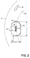
- a magnetic disk 10 (shown in broken line in Figures 1 and 2 so as to reveal underlying structure) is mounted for rotation by a drive motor 12.
- the motor 12 has a spindle 14 connecting to a hub 16 that is securely attached to an inside periphery of the disk 10.
- a stabilizer device 18 includes a stabilizing block 20 having an opening 22 for exposing a magnetic head 24 to the surface of the disk 10.
- a circumferential, flat air bearing surface 26 surrounds the opening 22 on the side of the block 20 that faces the disk 10. Though the circumferential surface 26 is shown to be oval in shape, no particular shape is required for practice of the invention.
- the preferred embodiment is used in a system in which the head 24 traces a circular track 25 during recording and repeatedly traces the same track 25 during reproduction.
- Each track can correspond, for example, to a single video picture in a still video recording/reproduction system.
- the opening 22 leads to a cavity 23 in the block 20.
- the head 24 is mounted on the shoe 30 to locate a magnetic gap 32 in relation to the opening 22 so that the gap 32 slightly protrudes above the plane of the air bearing surface 26.
- the stabilizing block 20 is supported with respect to the disk 10 along a flat inclined surface 33 of a wedge-shaped support 34 mounted upon a conventional head positioning carriage (not shown).
- the support 34 and the head 24 therewith are disposed at a particular angle (the attack angle) with respect to magnetic track movement and at a further particular angle (the tilt angle) with respect to a radial of the disk 10.
- the precise dimensions of the stabilizer are not critical and may vary depending upon the size of the disk, head structure, etc., it may be helpful to disclose the particular dimensions used in connection with a single track head for recording fifty circular tracks on a disk 47 mm in diameter.
- the length L of a suitable stabilizing block 20 in this environment is 0.350 inches and the width W is 0.250 inches. Even for these disk and track dimensions, other stabilizer dimensions are likely to be suitable.
- this invention applies to any size disk with attendent changes, if necessary, in the stabilizer dimensions.
- the magnetic disk 10 When the magnetic disk 10 is rapidly rotated by the drive motor 12 in a direction shown by an arrow 36, successive portions of the disk 10 encounter a leading curved edge 38 of the flat air bearing surface 26.
- the angle of the wedge-shaped support 34 which defines the attack angle, limits penetration of the leading curved edge 38 into a nominal plane 40 of the disk 10. (The nominal plane is the plane established by the rotating disk absent any interference.)
- the extent of penetration is generally quite small, e.g., 0.006 in.
- the attack angle should be as small as possible to prevent wear of the transducer and/or media surfaces.
- the air bearing surface 26 is disposed at a negative angle of attack of 2.3° and at a tilt angle of 0°.
- the magnetic interface should be maintainable at a variety of attack angles, tilt angles, and penetration distances because assembly of the head, stabilizer and wedge requires tolerance of some assembly variation. Furthermore, since the attack angle and the tilt angle are measured with respect to the nominal plane 40 of the disk 10, any perturbation of a local area of the disk 10 such as caused by a warp has the effect of varying the attack and tilt angles and of thus compounding the tolerance required for assembly.
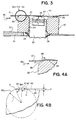
- the invention is concerned with the shape of the leading edge 38.
- the joinder with the flat surface 26′ parallel to surface 26
- the joinder with the flat surface 26′ would be in tangential relation, that is, the line defined by the surface 26′ would be tangent to the circle described by radius r.
- This broken line surface 26′, and the broken line portion 38a′ in fact describe the blended type of leading edge found in the prior art (typified by the aforementioned U.S. patents 4,620,250 and 4,578,727).
- the edge-tracing radius r meets the air bearing surface 26 at an included angle 42 that is acute, rather than at a right angle 42′, as in the prior art.
- the air bearing surface 26 coincides with a chord PQ of the circle defined by the radius r.
- the perpendicular distance d of this chord PQ from the broken line surface 26′ is between 0.0005 and 0.0015 inches.
- the transition point P is one of many points defining a curved line 44 that first meets the surface of the disk 10 as it is rotated over the penetrating leading edge 38 of the stabilizer 18.
- This curved line 44 again shown as a point P in Figure 4A, serves as a fulcrum about which the contacting section of the disk 10 attempts to rotate.
- a torque force is generated according to an arrow 46 ( Figure 4A) that attempts to twist the disk 10 clockwise. This force serves to deflect the disk 10 from its nominal plane 40 firmly upon the air bearing surface 26 despite any irregularities such as warps.
- leading edge 38 operates as an "air scraper” to choke off the flow of moving air over the air bearing surface 26, thereby forming a Bernoulli pull down force across the surface, which also helps to deflect the disk 10 from its nominal plane 40.
- air scraper operates as an "air scraper" to choke off the flow of moving air over the air bearing surface 26, thereby forming a Bernoulli pull down force across the surface, which also helps to deflect the disk 10 from its nominal plane 40.
- air will be removed from the cavity, causing the formation of a negative low pressure in the cavity. This negative pressure generates a pull down force on successive portions of the rotated disk 10 as each portion is moved across the opening, which further deflects the disk 10 into contact with the transducer gap 32 of the head 24.
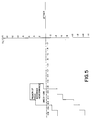
- Figure 5 describes the region of good interface performance for a system using a stabilizer of the prior art, that is, a stabilizer having the configuration including the broken line portions 38a′ and 26′ shown by Figure 4B.
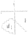
- Figure 6 shows the region of good interface performance for a stabilizer having an air bearing surface 26 that meets the leading edge 38 in a non-tangential relation at a point P as shown by Figure 4B, that is, in accordance with the invention.
- the areas of each region are multiples of tilt degrees by attack degrees, that is, (degrees)2.
- the invention provides a significant improvement by giving good performance over a much broader range of angles for a given head penetration. This makes assembly less critical and, importantly, permits greater confidence in lessened attack angle with attendant benefits of lesser head and media wear. But most significantly in terms of this invention, the effective variation in attack and tilt angles caused by warps or other local deformations of the medium can be accommodated within the large region of good interface performance (assuming the same head penetration is maintained).
- the stabilizer may have an opening 50 large enough to accommodate a dual gap head 52 for tracing two tracks 54a and 54b.
- different types of head structure may be accommodated.
- Figure 7 shows an opening to a negative pressure cavity sufficient to contain the dual transducing gaps of a thin-film head 52 rather than a wound ferrite head.
- a stabilizer with a non-tangential transition edge 44 may be manufactured in any number of conventional ways.
- One way that works especially well is to manufacture a stabilizer of the type disclosed by the prior art, that is, a stabilizer with a continuation of the blended radius leading edge 38a′, as shown in Figure 4B, leading into the surface 26′. Then the surface 26′ is lapped by conventional techniques until the lapped surface coincides with the air bearing surface 26 shown in Figure 4B. This requires removal of a thickness corresponding to the distance d, that is, between 0.0005 and 0.0015 inch.
Landscapes
- Supporting Of Heads In Record-Carrier Devices (AREA)
- Magnetic Record Carriers (AREA)
- Rotational Drive Of Disk (AREA)
Claims (3)
einem Stabilisatorblock (20), der eine Vertiefung (23) aufweist, in der der Wandler (24) auf einer dem sich vorwärtsbewegenden Speichermedium (10) zugewandten Blockseite gelagert ist,
einer glatt abgerundeten Vorderkante (38) auf der dem sich vorwärtsbewegenden Speichermedium (10) zugewandten Blockseite,
einer flachen umlaufenden Luftlagerfläche (26), die die Vertiefung (23) auf der dem Speichermedium (10) zugewandten Seite des Stabilisatorblocks (20) umgibt, und
Mitteln (33), die den Stabilisatorblock (20) und das Speichermedium (10) so in einem Winkel zueinander positionieren, daß die abgerundete Kante (38) mit dem Speichermedium (10) in Berührung kommt und dieses zu dem Wandler (24) hin ablenkt, dadurch gekennzeichnet, daß
die flache Luftlagerfläche (20) die abgerundete Vorderkante (38) schneidet und an der Schnittstelle einen scharfen Übergang (P) erzeugt, der ein abruptes winkelförmiges Ende der abgerundeten Vorderkante (38) an der Anschlußstelle mit der flachen Luftlagerfläche (20) bildet, derart, daß das Speichermedium (10) über den scharfen Übergang (P) abgelenkt wird.
Applications Claiming Priority (2)
| Application Number | Priority Date | Filing Date | Title |
|---|---|---|---|
| US19468 | 1987-02-26 | ||
| US07/019,468 US4792874A (en) | 1987-02-26 | 1987-02-26 | Stabilizer device having an edge configuration for stabilizing the interface between a transducer and a moving medium |
Publications (2)
| Publication Number | Publication Date |
|---|---|
| EP0303671A1 EP0303671A1 (de) | 1989-02-22 |
| EP0303671B1 true EP0303671B1 (de) | 1992-05-06 |
Family
ID=21793387
Family Applications (1)
| Application Number | Title | Priority Date | Filing Date |
|---|---|---|---|
| EP88902333A Expired - Lifetime EP0303671B1 (de) | 1987-02-26 | 1988-02-26 | Stabilisatoreinrichtung mit einer kante, die den zwischenraum zwischen einem wandler und einem datenträger in bewegung stabilisiert |
Country Status (5)
| Country | Link |
|---|---|
| US (1) | US4792874A (de) |
| EP (1) | EP0303671B1 (de) |
| JP (1) | JPH01502943A (de) |
| DE (1) | DE3870760D1 (de) |
| WO (1) | WO1988006788A1 (de) |
Families Citing this family (7)
| Publication number | Priority date | Publication date | Assignee | Title |
|---|---|---|---|---|
| US4833556A (en) * | 1987-12-22 | 1989-05-23 | Eastman Kodak Company | Low drag stabilizer device for stabilizing the interface between a transducer and a moving medium |
| US4928196A (en) * | 1988-04-04 | 1990-05-22 | Eastman Kodak Company | Magnetic recording device using circumferentially offset heads with double sided media |
| JPH0256765A (ja) * | 1988-08-23 | 1990-02-26 | Alps Electric Co Ltd | 磁気ヘッド支持装置 |
| JPH02156493A (ja) * | 1988-12-09 | 1990-06-15 | Victor Co Of Japan Ltd | 浮上型磁気ヘッド構体 |
| EP0446916B1 (de) * | 1990-03-15 | 1998-08-05 | Canon Kabushiki Kaisha | Kamera zur Verwendung eines Magnetschichtspeichers |
| JP3311362B2 (ja) * | 1991-04-10 | 2002-08-05 | 株式会社日本コンラックス | 情報記録再生装置 |
| US6362935B1 (en) * | 1999-04-20 | 2002-03-26 | Iomega Corporation | Chamfered head for enhanced loading onto media |
Family Cites Families (11)
| Publication number | Priority date | Publication date | Assignee | Title |
|---|---|---|---|---|
| US3821813A (en) * | 1972-12-27 | 1974-06-28 | Ibm | Wasp waist head for flying flexible magnetic storage medium over head |
| US4003091A (en) * | 1976-03-08 | 1977-01-11 | International Business Machines Corporation | Transducer support and stabilizer |
| US4151573A (en) * | 1977-06-13 | 1979-04-24 | Tandon Magnetics Corp. | Magnetic recording device for double sided media |
| US4396965A (en) * | 1979-08-06 | 1983-08-02 | Burroughs Corporation | Flying head with foil support |
| US4379315A (en) * | 1980-10-21 | 1983-04-05 | Applied Magnetics Corporation | Carriage loading arm assembly having two magnetic transducers for a double sided floppy disc |
| US4376960A (en) * | 1980-12-31 | 1983-03-15 | International Business Machines Corporation | Flexible disk stabilizing structure |
| US4414592A (en) * | 1981-05-01 | 1983-11-08 | Iomega Corporation | Support for stabilizing the movement of a magnetic medium over a magnetic head |
| JPS60150264A (ja) * | 1984-01-17 | 1985-08-07 | Fujitsu Ltd | 磁気ヘツド支持器 |
| US4578727A (en) * | 1984-02-27 | 1986-03-25 | Eastman Kodak Company | Device for stabilizing the movement of a floppy disk over a magnetic head |
| US4620250A (en) * | 1984-03-29 | 1986-10-28 | Eastman Kodak Company | Transducer-to-medium stabilizing device at negative attack angle with respect to medium |
| JPS619868A (ja) * | 1984-06-25 | 1986-01-17 | Olympus Optical Co Ltd | 磁気記録再生装置 |
-
1987
- 1987-02-26 US US07/019,468 patent/US4792874A/en not_active Expired - Fee Related
-
1988
- 1988-02-26 JP JP63502305A patent/JPH01502943A/ja active Pending
- 1988-02-26 EP EP88902333A patent/EP0303671B1/de not_active Expired - Lifetime
- 1988-02-26 WO PCT/US1988/000530 patent/WO1988006788A1/en not_active Ceased
- 1988-02-26 DE DE8888902333T patent/DE3870760D1/de not_active Expired - Fee Related
Non-Patent Citations (1)
| Title |
|---|
| IBM Technical Disclosure Bulletin, vol. 27, no. 2, July 1984 (New York, US), A. R. Cox et al.: "Head assembly for flexible disk applications", pages 1294-1295 * |
Also Published As
| Publication number | Publication date |
|---|---|
| DE3870760D1 (de) | 1992-06-11 |
| JPH01502943A (ja) | 1989-10-05 |
| EP0303671A1 (de) | 1989-02-22 |
| WO1988006788A1 (en) | 1988-09-07 |
| US4792874A (en) | 1988-12-20 |
Similar Documents
| Publication | Publication Date | Title |
|---|---|---|
| US4833556A (en) | Low drag stabilizer device for stabilizing the interface between a transducer and a moving medium | |
| EP0049755B1 (de) | Magnetkopf-Anordnung | |
| EP0372990A2 (de) | Magnetisches Aufzeichnungsgerät | |
| EP0303671B1 (de) | Stabilisatoreinrichtung mit einer kante, die den zwischenraum zwischen einem wandler und einem datenträger in bewegung stabilisiert | |
| US4367505A (en) | Magnetic head assembly with skewed read/write gap | |
| US4928196A (en) | Magnetic recording device using circumferentially offset heads with double sided media | |
| JPH02165410A (ja) | 回転ヘッド式磁気記録再生装置 | |
| US20040222327A1 (en) | Tape guide for reducing lateral tape movement | |
| US5007040A (en) | Magnetic recording and/or reproducing apparatus having a retaining mechanism for a disc-shaped magnetic record bearing medium | |
| EP0381741B1 (de) | VORRICHTUNG ZUM DOPPELSEITIGEN MAGNETISCHEN AUFZEICHNEN,DIE ZWEI WANDLER IN FESTER BEZIEHUNG ZUEINANDER TRäGT | |
| EP0378220B1 (de) | Aufzeichnungs-/Wiedergabegerät mit drehbaren Magnetköpfen | |
| JP2604420Y2 (ja) | 回転ヘッドドラム | |
| US4514772A (en) | Apparatus for reading/writing data on magnetic disc | |
| JP2728136B2 (ja) | 磁気ヘツド支持装置 | |
| JPH0628082B2 (ja) | 磁気ヘッド | |
| JP2530702Y2 (ja) | 磁気記録再生装置の回転ヘツドアセンブリ | |
| JPH0525081Y2 (de) | ||
| JPS6240680A (ja) | 磁気記録媒体 | |
| JP2728751B2 (ja) | 磁気ヘッド支持装置 | |
| JP2749418B2 (ja) | 磁気ヘッド支持装置 | |
| JPH0214455A (ja) | 磁気記録再生装置の回転ヘッドアセンブリ | |
| JPH0773422A (ja) | ヘッドドラム装置 | |
| JPS6117268A (ja) | 磁気ヘツド装置 | |
| JPS6194267A (ja) | 積層形可撓性デイスク装置の分離ブレ−ド | |
| JPS63183671A (ja) | 磁気デイスク装置 |
Legal Events
| Date | Code | Title | Description |
|---|---|---|---|
| PUAI | Public reference made under article 153(3) epc to a published international application that has entered the european phase |
Free format text: ORIGINAL CODE: 0009012 |
|
| AK | Designated contracting states |
Kind code of ref document: A1 Designated state(s): BE DE FR GB NL |
|
| 17P | Request for examination filed |
Effective date: 19890214 |
|
| 17Q | First examination report despatched |
Effective date: 19901207 |
|
| GRAA | (expected) grant |
Free format text: ORIGINAL CODE: 0009210 |
|
| AK | Designated contracting states |
Kind code of ref document: B1 Designated state(s): BE DE FR GB NL |
|
| REF | Corresponds to: |
Ref document number: 3870760 Country of ref document: DE Date of ref document: 19920611 |
|
| ET | Fr: translation filed | ||
| PLBE | No opposition filed within time limit |
Free format text: ORIGINAL CODE: 0009261 |
|
| STAA | Information on the status of an ep patent application or granted ep patent |
Free format text: STATUS: NO OPPOSITION FILED WITHIN TIME LIMIT |
|
| 26N | No opposition filed | ||
| PGFP | Annual fee paid to national office [announced via postgrant information from national office to epo] |
Ref country code: GB Payment date: 19940127 Year of fee payment: 7 |
|
| PGFP | Annual fee paid to national office [announced via postgrant information from national office to epo] |
Ref country code: FR Payment date: 19940218 Year of fee payment: 7 |
|
| PGFP | Annual fee paid to national office [announced via postgrant information from national office to epo] |
Ref country code: NL Payment date: 19940228 Year of fee payment: 7 |
|
| PGFP | Annual fee paid to national office [announced via postgrant information from national office to epo] |
Ref country code: DE Payment date: 19940301 Year of fee payment: 7 |
|
| PGFP | Annual fee paid to national office [announced via postgrant information from national office to epo] |
Ref country code: BE Payment date: 19940309 Year of fee payment: 7 |
|
| PG25 | Lapsed in a contracting state [announced via postgrant information from national office to epo] |
Ref country code: GB Effective date: 19950226 |
|
| PG25 | Lapsed in a contracting state [announced via postgrant information from national office to epo] |
Ref country code: BE Effective date: 19950228 |
|
| BERE | Be: lapsed |
Owner name: EASTMAN KODAK CY (A NEW JERSEY CORP.) Effective date: 19950228 |
|
| PG25 | Lapsed in a contracting state [announced via postgrant information from national office to epo] |
Ref country code: NL Effective date: 19950901 |
|
| GBPC | Gb: european patent ceased through non-payment of renewal fee |
Effective date: 19950226 |
|
| PG25 | Lapsed in a contracting state [announced via postgrant information from national office to epo] |
Ref country code: FR Effective date: 19951031 |
|
| NLV4 | Nl: lapsed or anulled due to non-payment of the annual fee |
Effective date: 19950901 |
|
| PG25 | Lapsed in a contracting state [announced via postgrant information from national office to epo] |
Ref country code: DE Effective date: 19951101 |
|
| REG | Reference to a national code |
Ref country code: FR Ref legal event code: ST |