EP0303014B1 - Schalteinrichtung für eine elektrisch angetriebene Fussbodenreinigungsmaschine - Google Patents
Schalteinrichtung für eine elektrisch angetriebene Fussbodenreinigungsmaschine Download PDFInfo
- Publication number
- EP0303014B1 EP0303014B1 EP19880109161 EP88109161A EP0303014B1 EP 0303014 B1 EP0303014 B1 EP 0303014B1 EP 19880109161 EP19880109161 EP 19880109161 EP 88109161 A EP88109161 A EP 88109161A EP 0303014 B1 EP0303014 B1 EP 0303014B1
- Authority
- EP
- European Patent Office
- Prior art keywords
- switching
- counterweight
- lever
- pivot
- switch
- Prior art date
- Legal status (The legal status is an assumption and is not a legal conclusion. Google has not performed a legal analysis and makes no representation as to the accuracy of the status listed.)
- Expired - Lifetime
Links
- 238000004140 cleaning Methods 0.000 title claims description 16
- 238000005096 rolling process Methods 0.000 claims description 4
- 239000011248 coating agent Substances 0.000 claims description 3
- 238000000576 coating method Methods 0.000 claims description 3
- 230000003111 delayed effect Effects 0.000 description 2
- 239000000428 dust Substances 0.000 description 2
- 238000000034 method Methods 0.000 description 2
- 230000000994 depressogenic effect Effects 0.000 description 1
- 239000007788 liquid Substances 0.000 description 1
- 230000001960 triggered effect Effects 0.000 description 1
- 238000005406 washing Methods 0.000 description 1
Images
Classifications
-
- A—HUMAN NECESSITIES
- A47—FURNITURE; DOMESTIC ARTICLES OR APPLIANCES; COFFEE MILLS; SPICE MILLS; SUCTION CLEANERS IN GENERAL
- A47L—DOMESTIC WASHING OR CLEANING; SUCTION CLEANERS IN GENERAL
- A47L11/00—Machines for cleaning floors, carpets, furniture, walls, or wall coverings
- A47L11/40—Parts or details of machines not provided for in groups A47L11/02 - A47L11/38, or not restricted to one of these groups, e.g. handles, arrangements of switches, skirts, buffers, levers
- A47L11/4002—Installations of electric equipment
- A47L11/4008—Arrangements of switches, indicators or the like
-
- H—ELECTRICITY
- H01—ELECTRIC ELEMENTS
- H01H—ELECTRIC SWITCHES; RELAYS; SELECTORS; EMERGENCY PROTECTIVE DEVICES
- H01H35/00—Switches operated by change of a physical condition
- H01H35/02—Switches operated by change of position, inclination or orientation of the switch itself in relation to gravitational field
- H01H35/027—Switches operated by change of position, inclination or orientation of the switch itself in relation to gravitational field the inertia mass activating the switch mechanically, e.g. through a lever
Definitions
- the invention relates to a device for switching an electrically driven floor cleaning machine according to the preamble of claim 1.
- Machines which are equipped with mechanically driven, rotating brushes and which are moved by the person working with the machine on a guide handle over the floor surface to be cleaned are preferably used for cleaning floor coverings.
- the guide shaft is preferably articulated on the floor cleaning machine and is pivoted from the non-use position into the use position and back.
- the guide shaft is provided with a switching device for the electric motor drive.
- the electrical power cord is wound up on a holder on the handle when not in use.
- the dust collection container with the suction fan unit or a container to be filled with washing liquid is generally attached to the guide shaft.
- the guide handle In the non-use position, the guide handle is in the vertical or a few degrees beyond the vertical raised and locked in this position against accidental tipping.
- the guide handle is pivoted from the vertical to the use position by approx. 45 °, for which purpose the locking of the non-use position is usually released using a pedal.
- the machine is usually switched on via a manually operated switch, which is often designed such that the lever actuating the electrical switch must be held in its switched-on position by hand while working with the machine, simultaneously with the guide handle, which is very annoying and is perceived as disturbing.
- Machines are also known in which the electrical switch for the drive motor is switched on when the guide shaft is pivoted into its use position and the motor is switched off again when the guide shaft is pivoted up into the non-use position.
- This automatic switching on and off of the machine by pivoting the guide handle has the disadvantage that the machine starts when the guide handle is moved only a few degrees from its non-use position towards the use position, which often gets the machine out of control. It is entirely possible to set the switching time for switching on the machine in such a way that the guide handle is almost in the position of use when the machine is switched on.
- a plunger is built into the bearing block of the guide rod with a rotatable ball guided in a groove in the guide rod bearing, which is limited so that the plunger is depressed and a pushbutton switch located below it is switched off when the guide rod moves from the working position into the upper or lower rest position pivots.
- this design requires a main switch, which is to be switched on when the guide rod is in the vertical position, and moreover a relatively complex structural design of the bearing design of the guide rod.
- the invention has for its object to provide a device for switching an electrically powered floor cleaning machine, in which the switching times, especially when using commercially available pressure switches are delayed so that no unintended switching operations are triggered when the guide shaft swings within its position of use.
- a lever pivotably mounted about an axis of rotation rests on the switch contact, for example a switch rod of an electrical switch.
- the other end of this lever is with his Distance to the axis of rotation of the lever - depending on its inclination - provide changing load weight.
- the part of the lever provided with the load weight assumes a position inclined downward at an angle of approximately 30 °.
- the load weight is at its extreme end and thus at the greatest distance from the axis of rotation of the lever, as a result of which the end of the lever which is in contact with the switching rod of the switch, preferably a pressure switch, exerts its greatest compressive force on the switching rod and against the latter Pressure of a spring acting on the switching rod is moved back into the pressure switch and thus opens the current circuit in the switch.
- the switching rod of the switch preferably a pressure switch
- the lever When the guide handle is tilted to its use position of approx. 45 °, the lever is raised from its position inclined downwards at approx. 30 ° to a position of a few angular degrees above the horizontal.
- the load weight movably mounted on the lever moves in the direction of the axis of rotation of the lever, so that the pressure of the end of the lever abutting the switching rod of the pressure switch is reduced against the restoring force of the pressure switch and the pressure switch closes the current flow, the lever in a position of approximately 30 ° is pivoted upwards.
- the movable load weight is designed in the form of a double roller. The two roller parts are connected to one another by a connecting bolt which rolls on a surface of the lever designed as a roller track.
- This rolling load weight causes a certain delay due to its inertia in the movement, so that only a few degrees before reaching the respective end position - non-use position / Position of use - the handle of the switching process is initiated and is therefore delayed.
- the range of movement of the load weight is limited by end stops.
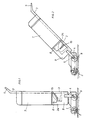
- the floor cleaning machine 1 is provided with a motor-driven brush 2 and is supported on rollers 6.
- the cleaning machine is moved with forward and backward movements over the floor surface to be cleaned (Fig. 2 and 4) on the guide handle 3, which is pivotally mounted on the floor cleaning machine 1 and is pivoted about 45 ° in the use position.
- a handle 5 is attached for easy handling.
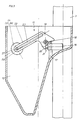
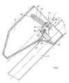
- the switching device 15 (FIGS. 3 and 4) is also accommodated in this receiving housing 10.
- the electrical pressure switch 16 is fastened on the holder 17.
- the shift lever 19 is rotatably mounted about the axis of rotation 18.
- the switch lever 19 rests with its one end 20 on the switch contact 21 - in the exemplary embodiment designed as a switch rod - of the pressure switch 16, this switch rod being axially movable in the pressure switch 16 against the force of a spring.
- the other end 22 of the shift lever 19 is provided with an elongated opening 23 in which a load weight 24 designed as a double roller 25, 26 is mounted in a positionally variable manner.
- the handle 3 of the floor cleaning machine 1 is in the use position.
- the shift lever 19 is inclined at about 30 ° upward, and the position-changing load weight 24 is in its closest position to the pivot point 18 of the shift lever 19, whereby the shift lever 19 is completely relieved of the load weight 24, so that the shift rod 21 of the pressure switch 16 loading spring moves the switching rod 21 out of the pressure switch 16, whereby the circuit is closed and the cleaning machine is switched on. Due to the force of the spring of the pressure switch 16 acting on the shift rod 21, the relieved shift lever 19 is raised further, whereby the load weight 24 rolls on until the end stop, so that the shift lever 19 remains inclined upward about 35 ° above the horizontal.
- the surface of the bolt 27 or Surface of the runway 28 with an anti-slip coating, such as Rubber, rubber or similar, provided.
- the switching rod 21 of the pressure switch 16 is arranged approximately perpendicular to the longitudinal axis of the guide stem 3.
- the switching rod 21 of the pressure switch 16 is arranged approximately parallel to the longitudinal axis of the guide stem 3 or at any angle thereto.
Landscapes
- Railway Tracks (AREA)
- Mechanisms For Operating Contacts (AREA)
Applications Claiming Priority (2)
| Application Number | Priority Date | Filing Date | Title |
|---|---|---|---|
| DE19873723445 DE3723445A1 (de) | 1987-07-16 | 1987-07-16 | Schalteinrichtung fuer eine elektrisch angetriebene fussbodenreinigungsmaschine |
| DE3723445 | 1987-07-16 |
Publications (2)
| Publication Number | Publication Date |
|---|---|
| EP0303014A1 EP0303014A1 (de) | 1989-02-15 |
| EP0303014B1 true EP0303014B1 (de) | 1991-12-11 |
Family
ID=6331640
Family Applications (1)
| Application Number | Title | Priority Date | Filing Date |
|---|---|---|---|
| EP19880109161 Expired - Lifetime EP0303014B1 (de) | 1987-07-16 | 1988-06-09 | Schalteinrichtung für eine elektrisch angetriebene Fussbodenreinigungsmaschine |
Country Status (2)
| Country | Link |
|---|---|
| EP (1) | EP0303014B1 (cg-RX-API-DMAC10.html) |
| DE (1) | DE3723445A1 (cg-RX-API-DMAC10.html) |
Family Cites Families (4)
| Publication number | Priority date | Publication date | Assignee | Title |
|---|---|---|---|---|
| DE7505621U (de) * | 1975-07-17 | Fakir Werk Kicherer W | Sicherheitsschalteinrichtung an einer FuBbodenreinigungsmaschine | |
| DE500632C (de) * | 1927-04-26 | 1930-06-24 | Inventia Patent Verwert Ges | Stromein- und -ausschaltvorrichtung fuer elektrisch betriebene Bohnermaschinen |
| AT218198B (de) * | 1958-08-08 | 1961-11-10 | Hoover Ltd | Elektromotorisch angetriebenes, auf frei drehbaren Rädern fahrbares Gerät, insbesondere Fußbodenbearbeitungsgerät |
| DD139064A3 (de) * | 1977-05-10 | 1979-12-12 | Moeller Klaus Henning | Schaltsicherungseinrichtung an einer fussbodenpflegemaschine |
-
1987
- 1987-07-16 DE DE19873723445 patent/DE3723445A1/de active Granted
-
1988
- 1988-06-09 EP EP19880109161 patent/EP0303014B1/de not_active Expired - Lifetime
Also Published As
| Publication number | Publication date |
|---|---|
| EP0303014A1 (de) | 1989-02-15 |
| DE3723445A1 (de) | 1989-02-02 |
| DE3723445C2 (cg-RX-API-DMAC10.html) | 1989-05-03 |
Similar Documents
| Publication | Publication Date | Title |
|---|---|---|
| DE2548656A1 (de) | Verriegelungseinrichtung fuer einen schalter eines elektrischen geraetes | |
| EP0347869B1 (de) | Tragbares, motorgetriebenes Schneidgerät, insbesondere Motorsäge, Heckenschere od.dgl. | |
| DE4437513A1 (de) | Vorrichtung zum Einsetzen in eine Badewanne oder dergleichen als Ein- und Ausstiegshilfe | |
| DE10360932A1 (de) | Kraftwerkzeug-Trigger | |
| DE102004042226A1 (de) | Deichsel für einen Mitgeh- und Mitfahrstapler | |
| DE4206515C1 (cg-RX-API-DMAC10.html) | ||
| DE2301471A1 (de) | Elektrischer schalter fuer tragbare elektrische geraete | |
| DE4421746C2 (de) | Motorisch angetriebene Heckenschere mit Zweihand-Sicherheitsbedienung | |
| DE2736613C2 (de) | Totmannschalter | |
| DE3723445C2 (cg-RX-API-DMAC10.html) | ||
| DE1299383B (de) | Kaffeemuehle mit einem elektrischen Antrieb und einem als Dosiervorrichtung dienenden Zeitschaltwerk | |
| EP1049834A1 (de) | Sicherheitsanordnung für die bedienungselemente einer handgeführten bodenverdichtungswalze | |
| DE602004013191T2 (de) | Elektrowerkzeug mit doppelt steuerbarem schalter | |
| EP0038287B1 (de) | Drehgriff zur Handbetätigung eines Kraftantriebes | |
| DE19948754C2 (de) | Waage mit motorisch betätigbarem Windschutz | |
| DE3037741C2 (de) | Antriebsvorrichtung für einen Schlitten | |
| EP1627848A2 (de) | Flurförderzeug mit ergonomisch angeordneten Bedienelementen | |
| WO2006037254A1 (de) | Vorrichtung zum kippen eines mit nahrungsmitteln füllbaren behälters in einer grossküche und steuereinrichtung hierfür | |
| DE3201689A1 (de) | Waschmaschine oder dgl. mit hilfsfahrwerk | |
| DE19756290A1 (de) | Elektrowerkzeug mit einem Ein/Aus-Schalter | |
| DE9410079U1 (de) | Motorisch angetriebene Heckenschere mit Zweihand-Sicherheitsbedienung | |
| DE1948389C3 (de) | Einrichtung zur Umschaltung der Laufrichtung des Papierwagens in Buchungs- oder ähnlichen Büromaschinen | |
| EP2546845A2 (de) | Versenkbare Drehknebeleinheit | |
| DE202024101668U1 (de) | Kettensägen-Sicherheitsmerkmal | |
| DE1166874B (de) | Elektrischer Druckknopfschalter mit Kontaktwippe |
Legal Events
| Date | Code | Title | Description |
|---|---|---|---|
| PUAI | Public reference made under article 153(3) epc to a published international application that has entered the european phase |
Free format text: ORIGINAL CODE: 0009012 |
|
| AK | Designated contracting states |
Kind code of ref document: A1 Designated state(s): BE DE FR GB IT LU NL SE |
|
| 17P | Request for examination filed |
Effective date: 19890429 |
|
| 17Q | First examination report despatched |
Effective date: 19900510 |
|
| RAP1 | Party data changed (applicant data changed or rights of an application transferred) |
Owner name: FEDAG |
|
| GRAA | (expected) grant |
Free format text: ORIGINAL CODE: 0009210 |
|
| AK | Designated contracting states |
Kind code of ref document: B1 Designated state(s): BE FR GB IT NL SE |
|
| ET | Fr: translation filed | ||
| ITF | It: translation for a ep patent filed | ||
| GBT | Gb: translation of ep patent filed (gb section 77(6)(a)/1977) | ||
| PLBE | No opposition filed within time limit |
Free format text: ORIGINAL CODE: 0009261 |
|
| STAA | Information on the status of an ep patent application or granted ep patent |
Free format text: STATUS: NO OPPOSITION FILED WITHIN TIME LIMIT |
|
| 26N | No opposition filed | ||
| PGFP | Annual fee paid to national office [announced via postgrant information from national office to epo] |
Ref country code: FR Payment date: 19930528 Year of fee payment: 6 |
|
| PGFP | Annual fee paid to national office [announced via postgrant information from national office to epo] |
Ref country code: GB Payment date: 19930603 Year of fee payment: 6 |
|
| PGFP | Annual fee paid to national office [announced via postgrant information from national office to epo] |
Ref country code: BE Payment date: 19930607 Year of fee payment: 6 |
|
| PGFP | Annual fee paid to national office [announced via postgrant information from national office to epo] |
Ref country code: SE Payment date: 19930628 Year of fee payment: 6 |
|
| PGFP | Annual fee paid to national office [announced via postgrant information from national office to epo] |
Ref country code: NL Payment date: 19930630 Year of fee payment: 6 |
|
| PG25 | Lapsed in a contracting state [announced via postgrant information from national office to epo] |
Ref country code: GB Effective date: 19940609 |
|
| PG25 | Lapsed in a contracting state [announced via postgrant information from national office to epo] |
Ref country code: SE Effective date: 19940610 |
|
| PG25 | Lapsed in a contracting state [announced via postgrant information from national office to epo] |
Ref country code: BE Effective date: 19940630 |
|
| BERE | Be: lapsed |
Owner name: FEDAG Effective date: 19940630 |
|
| PG25 | Lapsed in a contracting state [announced via postgrant information from national office to epo] |
Ref country code: NL Effective date: 19950101 |
|
| EUG | Se: european patent has lapsed |
Ref document number: 88109161.5 Effective date: 19950110 |
|
| GBPC | Gb: european patent ceased through non-payment of renewal fee |
Effective date: 19940609 |
|
| NLV4 | Nl: lapsed or anulled due to non-payment of the annual fee | ||
| PG25 | Lapsed in a contracting state [announced via postgrant information from national office to epo] |
Ref country code: FR Effective date: 19950228 |
|
| EUG | Se: european patent has lapsed |
Ref document number: 88109161.5 |
|
| REG | Reference to a national code |
Ref country code: FR Ref legal event code: ST |
|
| PG25 | Lapsed in a contracting state [announced via postgrant information from national office to epo] |
Ref country code: IT Free format text: LAPSE BECAUSE OF NON-PAYMENT OF DUE FEES;WARNING: LAPSES OF ITALIAN PATENTS WITH EFFECTIVE DATE BEFORE 2007 MAY HAVE OCCURRED AT ANY TIME BEFORE 2007. THE CORRECT EFFECTIVE DATE MAY BE DIFFERENT FROM THE ONE RECORDED. Effective date: 20050609 |