EP0301547B1 - Turbo-Verbundmaschine - Google Patents
Turbo-Verbundmaschine Download PDFInfo
- Publication number
- EP0301547B1 EP0301547B1 EP88112245A EP88112245A EP0301547B1 EP 0301547 B1 EP0301547 B1 EP 0301547B1 EP 88112245 A EP88112245 A EP 88112245A EP 88112245 A EP88112245 A EP 88112245A EP 0301547 B1 EP0301547 B1 EP 0301547B1
- Authority
- EP
- European Patent Office
- Prior art keywords
- gear
- exhaust gas
- engine
- power
- turbine
- Prior art date
- Legal status (The legal status is an assumption and is not a legal conclusion. Google has not performed a legal analysis and makes no representation as to the accuracy of the status listed.)
- Expired - Lifetime
Links
Images

Classifications
-
- F—MECHANICAL ENGINEERING; LIGHTING; HEATING; WEAPONS; BLASTING
- F02—COMBUSTION ENGINES; HOT-GAS OR COMBUSTION-PRODUCT ENGINE PLANTS
- F02B—INTERNAL-COMBUSTION PISTON ENGINES; COMBUSTION ENGINES IN GENERAL
- F02B41/00—Engines characterised by special means for improving conversion of heat or pressure energy into mechanical power
- F02B41/02—Engines with prolonged expansion
- F02B41/10—Engines with prolonged expansion in exhaust turbines
-
- Y—GENERAL TAGGING OF NEW TECHNOLOGICAL DEVELOPMENTS; GENERAL TAGGING OF CROSS-SECTIONAL TECHNOLOGIES SPANNING OVER SEVERAL SECTIONS OF THE IPC; TECHNICAL SUBJECTS COVERED BY FORMER USPC CROSS-REFERENCE ART COLLECTIONS [XRACs] AND DIGESTS
- Y02—TECHNOLOGIES OR APPLICATIONS FOR MITIGATION OR ADAPTATION AGAINST CLIMATE CHANGE
- Y02T—CLIMATE CHANGE MITIGATION TECHNOLOGIES RELATED TO TRANSPORTATION
- Y02T10/00—Road transport of goods or passengers
- Y02T10/10—Internal combustion engine [ICE] based vehicles
- Y02T10/12—Improving ICE efficiencies
Definitions
- the present invention relates to a turbo compound engine.
- Such engine is capable of recovering the energy of the exhaust gas as expansion work of a power turbine and of transmitting the recovered energy to a drive shaft of the engine via a gear train, so as to rotate the power turbine in a reverse sense upon deceleration of the vehicle in order to obtain a braking action.
- the invention relates to a turbo compound engine provided with a gear train having a clutch to absorb a large load produced when the power turbine is rotated in reverse sense.
- turbo compound engines which recover their exhaust gas energy as supercharging energy of a turbocharger and exhaust gas energy from the turbocharger as diabatic expansion energy of a power turbine.
- the power output performance, the fuel consumption rate, and the gain of the engine are improved by raising the expansion ratios of the turbocharger and of the power turbine.
- the braking action against the engine decreases with an increase of turbocharged pressure so that a main brake (i.e. foot brake) should be manipulated in order to offset the relative decrease of the entire braking action. Guarantee of a sufficient braking action is important not only for the maneuverability and safety of the vehicle (engine brake force of more than approximately 60 % of the rated output power is required), but also for utilizing the turbo compound engine more effectively.
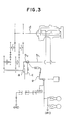
- turbo compound engines are mentioned in which, as shown in Fig 3 of the accompanying drawings, a power turbine a for recovering the exhaust gas energy is disposed in an exhaust passage b1 of a vehicle, and a fluid passage c3 is connected to an exhaust passage b2 upstream of the power turbine a so as to bypass the power turbine 1.
- Fluid passage switching means e is provided at the junction of the exhaust passage b1 upstream of the fluid passage c opening the fluid passage c when the vehicle is in deceleration mode and the driving power is transmitted from the crank shaft d to the power turbine a.
- This construction makes it possible that the power turbine recovers the exhaust gas energy from the engine so as to utilize the recovered energy as driving energy of the engine during the normal driving.
- the fluid passage switching means e closes the exhaust passage b1 upstream of the fluid passage c while connecting the passage b2 to the passage c with the junction of the two passages being throttled.
- the rotation of the crank shaft d is transmitted via one of the gear trains to the power turbine a, with the rotation reversed by the gear train.
- the power turbine a which is originally designed for energy recovery, performs pumping work i.e., the power turbine compresses the air from the exhaust passage b2 into the fluid passage c. Therefore, it is possible to obtain a large braking action including motor friction of the engine, negative work upon pumping work by the power turbine, and the exhaust braking force during exhaust braking.
- the power turbine rotates at a revolution speed ranging from 80,000 to 100,000 r.p.m. during normal driving of the vehicle, and the rotation energy at such a revolution speed is equivalent to the moment of the inertia (polar moment of inertia of area) of the flywheel of the normal engine.
- the rotation energy at such a revolution speed is equivalent to the moment of the inertia (polar moment of inertia of area) of the flywheel of the normal engine.
- said energy reaches its maximum if it takes a relatively short time (2-3 seconds) from the beginning of the reversing till the power turbine reaches its maximum speed in reverse direction.
- a turbo compound engine which can absorb said energy by certain means disposed between the crank shaft and the power turbine.
- One object of this invention is to provide a turbo compound engine including two gear trains for connection of a power recovering turbine, disposed in the exhaust line of the engine, with the output shaft of the engine so that the transmission direction of the driving power may be reversed, and a temporarily rapidly increasing large load may not be produced upon switching of the gear trains for reverse mode, whereby the useful life of the drive power transmitting system and driveability of the vehicle are improved.
- a turbo compound engine of the present invention includes power reversing means in the gear train which connects the output shaft of the engine with the power turbine, the power reversing means having a hydraulic clutch which slips upon connection of the hydraulic clutch so that the large energy, produced when the power turbine is rotated in reverse sense, is consumed at the hydraulic clutch.
- reference numeral 1 indicates an engine of a vehicle (not shown), 2 the intake manifold of the engine 1, and 3 the exhaust manifold of the engine 1.
- an exhaust gas passage 4a is connected to the exhaust manifold 3, and to the intake manifold 2 there is connected an intake-air passage 5.
- a turbine 10a of the turbocharger 10 is disposed at an intermediate point in the exhaust passage 4a while the compressor 10b of the turbocharger 10 is disposed in the intake passage 5.
- a power turbine 12 is disposed for recovering the exhaust gas energy.
- a fluid passage 25 branches from the exhaust gas passage 4b between the power turbine 12 and the turbine 10a of the turbocharger 10, and is connected to the passage 4c downstream of the power turbine 12.
- a passage switching means 30 for closing the fluid passage 25 while throttling the passage 4b to a predetermined degree.
- the switching means 30 is constructed to have at least two switching positions.
- An external atmosphere conduit 7 is connected to the exhaust passage 4c connecting the fluid passage 25 to the outlet port 6 of the power turbine 12.
- a switching means 31 which opens the external atmosphere conduit 7 upon closing of the exhaust gas passage 4c.
- an exhaust brake valve 32 is provided in the passage 4b between the switching valve 30 and the turbine 10a.
- an output gear 16 is disposed at the end 13a of the shaft 13 of the power turbine 12, and planetary gears 17a and 17b are engaged therewith.
- the planetary gears 17a and 17b are engaged with a ring gear 18 rotating together with an input pump wheel 21b of a fluid coupling 21 provided with a lock up mechanism 21a.
- the output gear 16 is connected to the fluid coupling 21 via the planetary gear mechanism 19 including the planetary gears 17a and 17b, so that the rotation of the power turbine 12 is transmitted to an output pump wheel 21c of the fluid coupling 21.
- the epicyclic gear 19 is employed for having a large moderating ratio and a high transmission efficiency
- Another epicyclic gear 40 for connecting the crank shaft 23 with the gear 20 and for rotating the power turbine 12 in both normal and reverse senses will be explained.
- the epicylic gear 40 comprises a sun gear 41, a sun gear shaft 42, a ring gear 44 engaged with planetary gears 43, at intervals in the circumferential direction thereof, and circumferentially surrounding the sun gear 41, and a carrier 45 for maintaining constant the relative positional relationship of the planetary gear 43 and the sun gear 41 while the planetary gear 43 rotates autorotationally and revolutionally around the sun gear 41.
- the epicyclic gear 40 will be explained in detail below.
- the sun gear shaft 42 is provided with a first transmission gear 46 engaged with the crank shaft gear 23 at one end thereof, and supports said carrier 45 by a bearing 47 near the other and thereof.
- the ring gear 44 is provided with a second transmission gear 48 engaged with the gear 20.
- the second transmission gear 48 includes a hollow shaft 49 housing a part of the sun gear shaft 42 between the first and second transmission gears 46 and 48.
- the hollow shaft 49 rotates about the shaft 42 and is provided with a one way clutch 50.
- the one way clutch connects the first transmission gear 46 with the shaft 49 only if drive power is transmitted from the gear 46 to the crank shaft 15.
- the carrier 45 includes a clutch element 51 extending outwardly in a radial direction The direction of rotation of the epicyclic gear 40 is controlled by hydraulic clutch means 55.
- the hydraulic clutch means 55 includes a hydraulic clutch 56 which can be connected to said clutch element 51 so as to stop the carrier 45 during the connection mode, a pump 56 supplying oil to the hydraulic clutch 56, a valve 59 disposed in an oil conduit 58 connecting the pump 57 with the hydraulic clutch 56, and a controller 60 controlling a valve 59.
- An ON-OFF signal from a clutch switch 62 of the engine 1, an ON-OFF signal from an accelerator switch 63, a rotating speed signal from a rotating speed sensor 61 of the engine 1, and a brake control signal from a brake control switch 64 are input into the controller 60 while control signals are output from the controller 60 to the switching valves 30 and 31, the exhaust brake valve 32, the epicyclic gear 19, and the partition valve 59.
- the brake control switch 64 of the illustrated embodiment has an OFF position, a position 1, and a position 2.
- the controller 60 outputs a command signal to fully close the exhaust brake valve 31 only, whereas at position 2, same outputs a command signal to close the exhaust passage 4c and to open the air inlet passage 7, a command signal to actuate the switching valve 30 of the fluid passage 25 to a predetermined extent for throttling, a command signal to fully close the partition valve 59 of the hydraulic clutch 56, and a command signal to cancel locking-up of the locking-up mechanism 21a.
- the controller 60 supplies command signals to the switching valve 30 for full closing of the fluid passage 25, to the switching valve 31 for full closing of the external atmosphere duct 7, to the locking-up mechanism 21a for locking-up, and to the valve 59 for full closing so as to allow the hydraulic clutch 56 to be free from the clutch element 51.
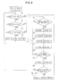
- the controller 60 during normal driving, it will be judged whether the accelerator switch 63 is OFF at step 70, whether the clutch switch 62 is ON at step 71, and whether the engine revolution speed is equal to or higher than 700 r.p.m. at step 72.
- the controller 60 detects that the vehicle is decelerated, and the following steps are executed. First, the exhaust brake valve 32 is fully closed at step 73 so as to increase the exhaust gas pressure, then it is judged whether the brake control switch 74 is in position 2 or not. If the answer at step 74 is NO, the program returns to step 70, and repeats the above-mentioned procedures. If one of the answers during steps 70 through 72 is NO, i.e.
- step 82 the program jumps to step 82. If the answer at step 74 is YES, the controller 60 sends a command signal to the locking-up mechanism 21a of the fluid clutch 21 for eliminating the locking-up as stated in the box labelled 75. Then, the controller sends a command signal to the valve 30 at step 76 so that the fluid passage 25 may be throttled to a predetermined extent while sending a signal at step 77 to the valve 31 so as to close the exhaust passage 4c and open the external atmosphere duct 7.
- the partition valve 59 is closed by a command signal at step 78.
- step 79 it is checked whether the connection of the hydraulic clutch 56 has lasted three minutes at step 79.
- steps 75 and 78 are repeated, so that the heat generation in the hydraulic clutch 56 is limited to a predetermined extent and no unduly large braking action is applied to the engine 1.
- the answer at step 79 is YES, the lock-up mechanism 21a starts working.
- the brake control switch 64 is still ON at step 81, i.e., if the control switch 64 is either in position 1 or 2, the above-described control for deceleration is repeated. This repetition of deceleration control makes it possible to gradually reduce the engine speed while suppressing load against the hydraulic clutch 56.
- the control for normal driving is performed. More specifically, the controller 60 outputs command signals to the valves 30, 31, and 59, so as to turn off the hydraulic clutch 56 and close the fluid line 25 and the air duct 7. Thereupon, the power turbine 12 starts rotating in normal sense effected by the exhaust gas, so as to recover the energy of the exhaust gas, and the rotative power of normal direction is transmitted to the crank shaft 15 via the planetary gear 29, and the other gears 20, 48, 46, and 23.
Landscapes
- Engineering & Computer Science (AREA)
- Chemical & Material Sciences (AREA)
- Combustion & Propulsion (AREA)
- Mechanical Engineering (AREA)
- General Engineering & Computer Science (AREA)
- Supercharger (AREA)
Claims (7)
- Turbocompoundmaschine umfassend eine Brennkraftmaschine (1) mit einer Ausgangswelle (15), eine Abgasleitung (4a, 4b, 4c), einen die Ausgangswelle (15) der Brennkraftmaschine (1) mit einer in der Abgasleitung (4b) der Brennkraftmaschine (1) angeordneten Leistungsrückgewinnungsturbine (12) verbindenden Getriebezug, und einen Leistungsumkehrmechanismus in dem Getriebezug, wobei der Leistungsumkehrmechanismus einen Planetenzahnradsatz (40) enthält und eine hydraulische Rutschkupplungsanordnung (55) in dem Planetenzahnradsatz (40) so vorgesehen ist, daß sie die Ausgangswelle (15) der Brennkraftmaschine (1) mit der Leistungsrückgewinnungsturbine (12) bei deren Drehungsumkehr mit Schlupf verbindet, wodurch Energie absorbiert wird, die bei Drehungsumkehr der Leistungsrückgewinnungsturbine (12) erzeugt wird.
- Turbocompoundmaschine nach Anspruch 1, dadurch gekennzeichnet, daß die Abgasleitung (4b) eine Bypassleitung (25) für die Leistungsrückgewinnungsturbine (12) hat, der stromaufwärts ein Abgasbremsventil (32) vorgeordnet ist, daß ein Schaltventil (30) an einem Schnittpunkt der Bypassleitung (25) und der Abgasleitung (4b) zum Schließen der Abgasleitung (4b) und Öffnen der Bypassleitung (25) bei Fahrzeugverzögerung angeordnet ist, daß mit einem Teil der Abgasleitung (4c) zwischen der Bypassleitung (25) und der Austrittsöffnung (6) der Leistungsrückgewinnungsturbine (12) eine zur Außenatmosphäre führende Leitung (7) verbunden ist, und daß ein Schaltventil (31) an dem genannten Teil der Abgasleitung (4c) angeordnet ist, das ihn schließt und die zur Außenatmosphäre führende Leitung (7) öffnet.
- Turbocompoundmaschine nach Anspruch 1 oder 2, dadurch gekennzeichnet, daß die Leistungsumkehrmittel enthalten: ein Sonnenzahnrad (41), ein in dieses eingreifendes Planetenzahnrad (43), ein Ringzahnrad (44) mit Innenverzahnung (44a) in Eingriff mit dem Planetenzahnrad (43) und ein Außenzahnrad (48) in Eingriff mit einem mit der Leistungsrückgewinnungsturbine (12) verbundenen Zahnrad (20), die die Drehung des Planetenzahnrades (43) begrenzende Hydraulikkupplungsanordnung (55), ein Übertragungszahnrad (46) in Verbindung mit einer Hohlwelle (49) über eine Einwegkupplung (50) und drehbar mit dem Ringzahnrad (44) zum Eingriff mit einem Zahnrad (23) der Ausgangswelle (15) und zum Drehen mit einer durch die Hohlwelle (49) verlaufenden Achse (42) des Sonnenzahnrades (41).
- Turbocompoundmaschine nach einem der Ansprüche 1 bis 3, dadurch gekennzeichnet, daß die Hydraulikkupplung (55) eine Kupplungsscheibe (51) befestigt an einem Träger (45) des Planetenzahnrades (43), eine weitere Kupplungsscheibe gekoppelt mit der Kupplungsscheibe (51) und einen Betätiger (56) zum Einkuppeln und Auskuppeln der beiden Kupplungsscheiben abhängig von zugeführtem Öldruck enthält.
- Turbocompoundmaschine nach einem der vorhergehenden Ansprüche, dadurch gekennzeichnet, daß die Leistungsrückgewinnungsturbine (12) in der Abgasleitung (46) stromabwärts einer Turbine (10a) eines Turboladers (10) zur Rückgewinnung von Energie aus dem Abgas angeordnet ist, und daß eine Steuerung (60) zum Betätigen des Abgasbremsventils (32) und des Schaltventils (31) sowie zum schlupfbehafteten Verbinden der Ausgangswelle (15) mit der Leistungsrückgewinnungsturbine (12) über die hydraulische Kupplungsanordnung (55) bei deren Drehungsumkehr vorgesehen ist.
- Turbocompoundmaschine nach Anspruch 5, dadurch gekennzeichnet, daß die Steuerung (60) so aufgebaut ist, daß sie die Befehlssignale zum Schließen des Abgasbremsventils (32), zum Betätigen des Schaltventils (30) in der Bypassleitung (25) und des Schaltventils (31) stromabwärts der Leistungsrückgewinnungsturbine (12) sowie zum Einkuppeln der hydraulischen Kupplungsanordnung (55) erzeugt.
- Turbocompoundmaschine nach einem der vorhergehenden Ansprüche, dadurch gekennzeichnet, daß die hydraulische Kupplungsanordnung (55) nicht länger als drei Minuten nach dem Einkuppeln einen Schlupf hat.
Applications Claiming Priority (2)
| Application Number | Priority Date | Filing Date | Title |
|---|---|---|---|
| JP188747/87 | 1987-07-30 | ||
| JP62188747A JPS6435026A (en) | 1987-07-30 | 1987-07-30 | Turbo compound engine |
Publications (3)
| Publication Number | Publication Date |
|---|---|
| EP0301547A2 EP0301547A2 (de) | 1989-02-01 |
| EP0301547A3 EP0301547A3 (en) | 1989-08-09 |
| EP0301547B1 true EP0301547B1 (de) | 1992-10-14 |
Family
ID=16229065
Family Applications (1)
| Application Number | Title | Priority Date | Filing Date |
|---|---|---|---|
| EP88112245A Expired - Lifetime EP0301547B1 (de) | 1987-07-30 | 1988-07-28 | Turbo-Verbundmaschine |
Country Status (5)
| Country | Link |
|---|---|
| US (1) | US4843822A (de) |
| EP (1) | EP0301547B1 (de) |
| JP (1) | JPS6435026A (de) |
| CN (1) | CN1011607B (de) |
| DE (1) | DE3875300T2 (de) |
Families Citing this family (24)
| Publication number | Priority date | Publication date | Assignee | Title |
|---|---|---|---|---|
| US5119633A (en) * | 1990-09-25 | 1992-06-09 | Cummins Engine Company, Inc. | Power turbine bypass for improved compression braking |
| US5142868A (en) * | 1990-11-30 | 1992-09-01 | Cummins Engine Company, Inc. | Turbocompound engine with power turbine bypass control |
| US5474041A (en) * | 1994-12-28 | 1995-12-12 | Cummins Engine Company, Inc. | Engine lubrication system with decreased power draw |
| WO2002070877A1 (de) * | 2001-03-01 | 2002-09-12 | Voith Turbo Gmbh & Co. Kg | Antriebseinheit mit einem verbrennungsmotor und einem abgasturbolader |
| SE523149C2 (sv) * | 2001-08-20 | 2004-03-30 | Volvo Lastvagnar Ab | Anordning vid förbränningsmotor av turbocompoundtyp |
| DE10339857A1 (de) | 2003-08-29 | 2005-03-24 | Daimlerchrysler Ag | Brennkraftmaschine mit einer Motorbremseinrichtung |
| DE10348967B4 (de) * | 2003-10-22 | 2006-11-02 | Voith Turbo Gmbh & Co. Kg | Verfahren zur Optimierung des Nutzungsgrades in einer Antriebseinheit und Antriebseinheit |
| DE10360155A1 (de) * | 2003-12-20 | 2005-07-21 | Voith Turbo Gmbh & Co. Kg | Antriebsstrang mit Abgasnutzung und Steuerungsverfahren |
| DE102004002215B3 (de) | 2004-01-15 | 2005-09-08 | Voith Turbo Gmbh & Co. Kg | Antriebskraftübertragungsvorrichtung mit hydrodynamischer Gegenlaufkupplung |
| DE102005004058B3 (de) * | 2005-01-28 | 2006-05-24 | Voith Turbo Gmbh & Co. Kg | Turbo-Compound-System |
| US7281872B2 (en) | 2005-10-31 | 2007-10-16 | Hewlett-Packard Development Company, L.P. | Printer |
| US8294946B2 (en) | 2006-06-12 | 2012-10-23 | Hewlett-Packard Development Company, L.P. | Printer |
| WO2011160833A1 (en) * | 2010-06-22 | 2011-12-29 | Volvo Lastvagnar Ab | A turbo compound transmission and a method for controlling a turbo compound transmission |
| US8127544B2 (en) * | 2010-11-03 | 2012-03-06 | Paul Albert Schwiesow | Two-stroke HCCI compound free-piston/gas-turbine engine |
| DE102011012861A1 (de) * | 2011-03-02 | 2012-09-06 | Voith Patent Gmbh | Turbo-Compound-System, insbesondere eines Kraftfahrzeugs |
| JP5969800B2 (ja) * | 2012-04-12 | 2016-08-17 | サンデンホールディングス株式会社 | 流体機械及びランキンサイクル |
| DE102012010348A1 (de) * | 2012-05-25 | 2013-11-28 | GM Global Technology Operations LLC (n. d. Ges. d. Staates Delaware) | Verfahren und Vorrichtung zur Steuerung eineselektrischen Stellantriebes für eineWastegate-Ventilanordnung eines Abgasturboladers |
| US9108628B2 (en) * | 2012-08-31 | 2015-08-18 | GM Global Technology Operations LLC | Turbo compounding hybrid generator powertrain |
| CN103397934A (zh) * | 2013-07-04 | 2013-11-20 | 广西玉柴机器股份有限公司 | 内燃机废气回用装置 |
| EP2886826B1 (de) * | 2013-12-20 | 2016-09-28 | FPT Motorenforschung AG | Turbocompound-Anordnung, insbesondere im Industriefahrzeugbereich |
| CN104314695B (zh) * | 2014-09-30 | 2016-09-21 | 东风商用车有限公司 | 一种可变速比复合涡轮系统及其使用方法 |
| CN106224086B (zh) * | 2016-09-18 | 2018-11-23 | 重庆交通大学 | 混合动力汽车发动机废热余热再利用系统 |
| US10850860B1 (en) * | 2019-09-09 | 2020-12-01 | Hamiliton Sunstrand Corporation | Internal combustion engines with unidirectional compounding drives |
| CN110485983A (zh) * | 2019-09-20 | 2019-11-22 | 烟台杰瑞石油装备技术有限公司 | 一种涡轮压裂半挂车 |
Citations (2)
| Publication number | Priority date | Publication date | Assignee | Title |
|---|---|---|---|---|
| EP0272680A2 (de) * | 1986-12-26 | 1988-06-29 | Isuzu Motors Limited | Turbo-Verbund-Maschine |
| EP0297287A1 (de) * | 1987-05-30 | 1989-01-04 | Isuzu Motors Limited | Turboverbundmaschine |
Family Cites Families (6)
| Publication number | Priority date | Publication date | Assignee | Title |
|---|---|---|---|---|
| US2375852A (en) * | 1941-05-17 | 1945-05-15 | Sulzer Ag | Reversible supercharged twostroke internal-combustion engine |
| CH637707A5 (de) * | 1979-06-13 | 1983-08-15 | Rueti Ag Maschf | Webblatt fuer eine duesenwebmaschine. |
| JPS57824A (en) * | 1980-05-31 | 1982-01-05 | Matsushita Electric Works Ltd | Breaker with arc gas barrier |
| JPS61921A (ja) * | 1984-06-12 | 1986-01-06 | Hitachi Maxell Ltd | 磁気記録媒体 |
| US4745755A (en) * | 1985-07-26 | 1988-05-24 | Isuzu Motors Limited | Control system for supercharged internal combustion engine |
| DE3728681A1 (de) * | 1986-08-29 | 1988-03-10 | Isuzu Motors Ltd | Turbo-verbundkraftmaschine |
-
1987
- 1987-07-30 JP JP62188747A patent/JPS6435026A/ja active Granted
-
1988
- 1988-07-28 EP EP88112245A patent/EP0301547B1/de not_active Expired - Lifetime
- 1988-07-28 DE DE8888112245T patent/DE3875300T2/de not_active Expired - Fee Related
- 1988-07-29 US US07/226,176 patent/US4843822A/en not_active Expired - Lifetime
- 1988-07-29 CN CN88104535A patent/CN1011607B/zh not_active Expired
Patent Citations (2)
| Publication number | Priority date | Publication date | Assignee | Title |
|---|---|---|---|---|
| EP0272680A2 (de) * | 1986-12-26 | 1988-06-29 | Isuzu Motors Limited | Turbo-Verbund-Maschine |
| EP0297287A1 (de) * | 1987-05-30 | 1989-01-04 | Isuzu Motors Limited | Turboverbundmaschine |
Also Published As
| Publication number | Publication date |
|---|---|
| CN1011607B (zh) | 1991-02-13 |
| JPS6435026A (en) | 1989-02-06 |
| CN1031124A (zh) | 1989-02-15 |
| EP0301547A3 (en) | 1989-08-09 |
| DE3875300T2 (de) | 1993-04-01 |
| JPH0519017B2 (de) | 1993-03-15 |
| US4843822A (en) | 1989-07-04 |
| EP0301547A2 (de) | 1989-02-01 |
| DE3875300D1 (de) | 1992-11-19 |
Similar Documents
| Publication | Publication Date | Title |
|---|---|---|
| EP0301547B1 (de) | Turbo-Verbundmaschine | |
| US4800726A (en) | Turbo compound engine | |
| US4748812A (en) | Turbo compound engine | |
| EP0292010B1 (de) | Motorbremssystem | |
| JP4325783B2 (ja) | ガスタービン、前記ガスタービンを含む自動車およびガスタービンのエンジンブレーキ方法 | |
| JPH0519018B2 (de) | ||
| US4858440A (en) | Turbo-compound engine | |
| JPH01116229A (ja) | ターボコンパウンドエンジン | |
| JP2522790Y2 (ja) | ターボチヤージヤ | |
| JP3137802B2 (ja) | エンジンの過給装置 | |
| JP3137801B2 (ja) | エンジンの過給装置 | |
| JPH0517382B2 (de) | ||
| JPS63289220A (ja) | タ−ボコンパウンドエンジン | |
| JPH055230Y2 (de) | ||
| JPH01117940A (ja) | ターボコンパウンドエンジン | |
| JPS6219572B2 (de) | ||
| JPS63111239A (ja) | タ−ボコンパウンド機関 | |
| JPH0454221A (ja) | エンジンの過給装置 | |
| JP3060472B2 (ja) | 車両用エンジンの過給装置 | |
| JPH0637854B2 (ja) | タ−ボコンパウンドエンジン | |
| SU1229395A1 (ru) | Комбинированна силова установка | |
| JPH0299721A (ja) | トルクコンバータ搭載車のエンジン制御装置 | |
| JPH0523392Y2 (de) | ||
| JP2534558Y2 (ja) | ターボコンパウンドエンジンにおける過給システムの油圧式制御装置 | |
| JPH0519015B2 (de) |
Legal Events
| Date | Code | Title | Description |
|---|---|---|---|
| PUAI | Public reference made under article 153(3) epc to a published international application that has entered the european phase |
Free format text: ORIGINAL CODE: 0009012 |
|
| AK | Designated contracting states |
Kind code of ref document: A2 Designated state(s): AT BE CH DE ES FR GB GR IT LI LU NL SE |
|
| RBV | Designated contracting states (corrected) |
Designated state(s): DE GB |
|
| PUAL | Search report despatched |
Free format text: ORIGINAL CODE: 0009013 |
|
| AK | Designated contracting states |
Kind code of ref document: A3 Designated state(s): DE GB |
|
| 17P | Request for examination filed |
Effective date: 19900103 |
|
| 17Q | First examination report despatched |
Effective date: 19910227 |
|
| GRAA | (expected) grant |
Free format text: ORIGINAL CODE: 0009210 |
|
| AK | Designated contracting states |
Kind code of ref document: B1 Designated state(s): DE GB |
|
| REF | Corresponds to: |
Ref document number: 3875300 Country of ref document: DE Date of ref document: 19921119 |
|
| PLBE | No opposition filed within time limit |
Free format text: ORIGINAL CODE: 0009261 |
|
| 26N | No opposition filed | ||
| REG | Reference to a national code |
Ref country code: GB Ref legal event code: IF02 |
|
| PGFP | Annual fee paid to national office [announced via postgrant information from national office to epo] |
Ref country code: GB Payment date: 20050615 Year of fee payment: 18 |
|
| PGFP | Annual fee paid to national office [announced via postgrant information from national office to epo] |
Ref country code: DE Payment date: 20050617 Year of fee payment: 18 |
|
| PG25 | Lapsed in a contracting state [announced via postgrant information from national office to epo] |
Ref country code: GB Free format text: LAPSE BECAUSE OF NON-PAYMENT OF DUE FEES Effective date: 20060728 |
|
| PG25 | Lapsed in a contracting state [announced via postgrant information from national office to epo] |
Ref country code: DE Free format text: LAPSE BECAUSE OF NON-PAYMENT OF DUE FEES Effective date: 20070201 |
|
| GBPC | Gb: european patent ceased through non-payment of renewal fee |
Effective date: 20060728 |