EP0301547B1 - Turbo compound engine - Google Patents
Turbo compound engine Download PDFInfo
- Publication number
- EP0301547B1 EP0301547B1 EP88112245A EP88112245A EP0301547B1 EP 0301547 B1 EP0301547 B1 EP 0301547B1 EP 88112245 A EP88112245 A EP 88112245A EP 88112245 A EP88112245 A EP 88112245A EP 0301547 B1 EP0301547 B1 EP 0301547B1
- Authority
- EP
- European Patent Office
- Prior art keywords
- gear
- exhaust gas
- engine
- power
- turbine
- Prior art date
- Legal status (The legal status is an assumption and is not a legal conclusion. Google has not performed a legal analysis and makes no representation as to the accuracy of the status listed.)
- Expired - Lifetime
Links
Images

Classifications
-
- F—MECHANICAL ENGINEERING; LIGHTING; HEATING; WEAPONS; BLASTING
- F02—COMBUSTION ENGINES; HOT-GAS OR COMBUSTION-PRODUCT ENGINE PLANTS
- F02B—INTERNAL-COMBUSTION PISTON ENGINES; COMBUSTION ENGINES IN GENERAL
- F02B41/00—Engines characterised by special means for improving conversion of heat or pressure energy into mechanical power
- F02B41/02—Engines with prolonged expansion
- F02B41/10—Engines with prolonged expansion in exhaust turbines
-
- Y—GENERAL TAGGING OF NEW TECHNOLOGICAL DEVELOPMENTS; GENERAL TAGGING OF CROSS-SECTIONAL TECHNOLOGIES SPANNING OVER SEVERAL SECTIONS OF THE IPC; TECHNICAL SUBJECTS COVERED BY FORMER USPC CROSS-REFERENCE ART COLLECTIONS [XRACs] AND DIGESTS
- Y02—TECHNOLOGIES OR APPLICATIONS FOR MITIGATION OR ADAPTATION AGAINST CLIMATE CHANGE
- Y02T—CLIMATE CHANGE MITIGATION TECHNOLOGIES RELATED TO TRANSPORTATION
- Y02T10/00—Road transport of goods or passengers
- Y02T10/10—Internal combustion engine [ICE] based vehicles
- Y02T10/12—Improving ICE efficiencies
Definitions
- the present invention relates to a turbo compound engine.
- Such engine is capable of recovering the energy of the exhaust gas as expansion work of a power turbine and of transmitting the recovered energy to a drive shaft of the engine via a gear train, so as to rotate the power turbine in a reverse sense upon deceleration of the vehicle in order to obtain a braking action.
- the invention relates to a turbo compound engine provided with a gear train having a clutch to absorb a large load produced when the power turbine is rotated in reverse sense.
- turbo compound engines which recover their exhaust gas energy as supercharging energy of a turbocharger and exhaust gas energy from the turbocharger as diabatic expansion energy of a power turbine.
- the power output performance, the fuel consumption rate, and the gain of the engine are improved by raising the expansion ratios of the turbocharger and of the power turbine.
- the braking action against the engine decreases with an increase of turbocharged pressure so that a main brake (i.e. foot brake) should be manipulated in order to offset the relative decrease of the entire braking action. Guarantee of a sufficient braking action is important not only for the maneuverability and safety of the vehicle (engine brake force of more than approximately 60 % of the rated output power is required), but also for utilizing the turbo compound engine more effectively.
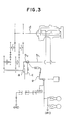
- turbo compound engines are mentioned in which, as shown in Fig 3 of the accompanying drawings, a power turbine a for recovering the exhaust gas energy is disposed in an exhaust passage b1 of a vehicle, and a fluid passage c3 is connected to an exhaust passage b2 upstream of the power turbine a so as to bypass the power turbine 1.
- Fluid passage switching means e is provided at the junction of the exhaust passage b1 upstream of the fluid passage c opening the fluid passage c when the vehicle is in deceleration mode and the driving power is transmitted from the crank shaft d to the power turbine a.
- This construction makes it possible that the power turbine recovers the exhaust gas energy from the engine so as to utilize the recovered energy as driving energy of the engine during the normal driving.
- the fluid passage switching means e closes the exhaust passage b1 upstream of the fluid passage c while connecting the passage b2 to the passage c with the junction of the two passages being throttled.
- the rotation of the crank shaft d is transmitted via one of the gear trains to the power turbine a, with the rotation reversed by the gear train.
- the power turbine a which is originally designed for energy recovery, performs pumping work i.e., the power turbine compresses the air from the exhaust passage b2 into the fluid passage c. Therefore, it is possible to obtain a large braking action including motor friction of the engine, negative work upon pumping work by the power turbine, and the exhaust braking force during exhaust braking.
- the power turbine rotates at a revolution speed ranging from 80,000 to 100,000 r.p.m. during normal driving of the vehicle, and the rotation energy at such a revolution speed is equivalent to the moment of the inertia (polar moment of inertia of area) of the flywheel of the normal engine.
- the rotation energy at such a revolution speed is equivalent to the moment of the inertia (polar moment of inertia of area) of the flywheel of the normal engine.
- said energy reaches its maximum if it takes a relatively short time (2-3 seconds) from the beginning of the reversing till the power turbine reaches its maximum speed in reverse direction.
- a turbo compound engine which can absorb said energy by certain means disposed between the crank shaft and the power turbine.
- One object of this invention is to provide a turbo compound engine including two gear trains for connection of a power recovering turbine, disposed in the exhaust line of the engine, with the output shaft of the engine so that the transmission direction of the driving power may be reversed, and a temporarily rapidly increasing large load may not be produced upon switching of the gear trains for reverse mode, whereby the useful life of the drive power transmitting system and driveability of the vehicle are improved.
- a turbo compound engine of the present invention includes power reversing means in the gear train which connects the output shaft of the engine with the power turbine, the power reversing means having a hydraulic clutch which slips upon connection of the hydraulic clutch so that the large energy, produced when the power turbine is rotated in reverse sense, is consumed at the hydraulic clutch.
- reference numeral 1 indicates an engine of a vehicle (not shown), 2 the intake manifold of the engine 1, and 3 the exhaust manifold of the engine 1.
- an exhaust gas passage 4a is connected to the exhaust manifold 3, and to the intake manifold 2 there is connected an intake-air passage 5.
- a turbine 10a of the turbocharger 10 is disposed at an intermediate point in the exhaust passage 4a while the compressor 10b of the turbocharger 10 is disposed in the intake passage 5.
- a power turbine 12 is disposed for recovering the exhaust gas energy.
- a fluid passage 25 branches from the exhaust gas passage 4b between the power turbine 12 and the turbine 10a of the turbocharger 10, and is connected to the passage 4c downstream of the power turbine 12.
- a passage switching means 30 for closing the fluid passage 25 while throttling the passage 4b to a predetermined degree.
- the switching means 30 is constructed to have at least two switching positions.
- An external atmosphere conduit 7 is connected to the exhaust passage 4c connecting the fluid passage 25 to the outlet port 6 of the power turbine 12.
- a switching means 31 which opens the external atmosphere conduit 7 upon closing of the exhaust gas passage 4c.
- an exhaust brake valve 32 is provided in the passage 4b between the switching valve 30 and the turbine 10a.
- an output gear 16 is disposed at the end 13a of the shaft 13 of the power turbine 12, and planetary gears 17a and 17b are engaged therewith.
- the planetary gears 17a and 17b are engaged with a ring gear 18 rotating together with an input pump wheel 21b of a fluid coupling 21 provided with a lock up mechanism 21a.
- the output gear 16 is connected to the fluid coupling 21 via the planetary gear mechanism 19 including the planetary gears 17a and 17b, so that the rotation of the power turbine 12 is transmitted to an output pump wheel 21c of the fluid coupling 21.
- the epicyclic gear 19 is employed for having a large moderating ratio and a high transmission efficiency
- Another epicyclic gear 40 for connecting the crank shaft 23 with the gear 20 and for rotating the power turbine 12 in both normal and reverse senses will be explained.
- the epicylic gear 40 comprises a sun gear 41, a sun gear shaft 42, a ring gear 44 engaged with planetary gears 43, at intervals in the circumferential direction thereof, and circumferentially surrounding the sun gear 41, and a carrier 45 for maintaining constant the relative positional relationship of the planetary gear 43 and the sun gear 41 while the planetary gear 43 rotates autorotationally and revolutionally around the sun gear 41.
- the epicyclic gear 40 will be explained in detail below.
- the sun gear shaft 42 is provided with a first transmission gear 46 engaged with the crank shaft gear 23 at one end thereof, and supports said carrier 45 by a bearing 47 near the other and thereof.
- the ring gear 44 is provided with a second transmission gear 48 engaged with the gear 20.
- the second transmission gear 48 includes a hollow shaft 49 housing a part of the sun gear shaft 42 between the first and second transmission gears 46 and 48.
- the hollow shaft 49 rotates about the shaft 42 and is provided with a one way clutch 50.
- the one way clutch connects the first transmission gear 46 with the shaft 49 only if drive power is transmitted from the gear 46 to the crank shaft 15.
- the carrier 45 includes a clutch element 51 extending outwardly in a radial direction The direction of rotation of the epicyclic gear 40 is controlled by hydraulic clutch means 55.
- the hydraulic clutch means 55 includes a hydraulic clutch 56 which can be connected to said clutch element 51 so as to stop the carrier 45 during the connection mode, a pump 56 supplying oil to the hydraulic clutch 56, a valve 59 disposed in an oil conduit 58 connecting the pump 57 with the hydraulic clutch 56, and a controller 60 controlling a valve 59.
- An ON-OFF signal from a clutch switch 62 of the engine 1, an ON-OFF signal from an accelerator switch 63, a rotating speed signal from a rotating speed sensor 61 of the engine 1, and a brake control signal from a brake control switch 64 are input into the controller 60 while control signals are output from the controller 60 to the switching valves 30 and 31, the exhaust brake valve 32, the epicyclic gear 19, and the partition valve 59.
- the brake control switch 64 of the illustrated embodiment has an OFF position, a position 1, and a position 2.
- the controller 60 outputs a command signal to fully close the exhaust brake valve 31 only, whereas at position 2, same outputs a command signal to close the exhaust passage 4c and to open the air inlet passage 7, a command signal to actuate the switching valve 30 of the fluid passage 25 to a predetermined extent for throttling, a command signal to fully close the partition valve 59 of the hydraulic clutch 56, and a command signal to cancel locking-up of the locking-up mechanism 21a.
- the controller 60 supplies command signals to the switching valve 30 for full closing of the fluid passage 25, to the switching valve 31 for full closing of the external atmosphere duct 7, to the locking-up mechanism 21a for locking-up, and to the valve 59 for full closing so as to allow the hydraulic clutch 56 to be free from the clutch element 51.
- the controller 60 during normal driving, it will be judged whether the accelerator switch 63 is OFF at step 70, whether the clutch switch 62 is ON at step 71, and whether the engine revolution speed is equal to or higher than 700 r.p.m. at step 72.
- the controller 60 detects that the vehicle is decelerated, and the following steps are executed. First, the exhaust brake valve 32 is fully closed at step 73 so as to increase the exhaust gas pressure, then it is judged whether the brake control switch 74 is in position 2 or not. If the answer at step 74 is NO, the program returns to step 70, and repeats the above-mentioned procedures. If one of the answers during steps 70 through 72 is NO, i.e.
- step 82 the program jumps to step 82. If the answer at step 74 is YES, the controller 60 sends a command signal to the locking-up mechanism 21a of the fluid clutch 21 for eliminating the locking-up as stated in the box labelled 75. Then, the controller sends a command signal to the valve 30 at step 76 so that the fluid passage 25 may be throttled to a predetermined extent while sending a signal at step 77 to the valve 31 so as to close the exhaust passage 4c and open the external atmosphere duct 7.
- the partition valve 59 is closed by a command signal at step 78.
- step 79 it is checked whether the connection of the hydraulic clutch 56 has lasted three minutes at step 79.
- steps 75 and 78 are repeated, so that the heat generation in the hydraulic clutch 56 is limited to a predetermined extent and no unduly large braking action is applied to the engine 1.
- the answer at step 79 is YES, the lock-up mechanism 21a starts working.
- the brake control switch 64 is still ON at step 81, i.e., if the control switch 64 is either in position 1 or 2, the above-described control for deceleration is repeated. This repetition of deceleration control makes it possible to gradually reduce the engine speed while suppressing load against the hydraulic clutch 56.
- the control for normal driving is performed. More specifically, the controller 60 outputs command signals to the valves 30, 31, and 59, so as to turn off the hydraulic clutch 56 and close the fluid line 25 and the air duct 7. Thereupon, the power turbine 12 starts rotating in normal sense effected by the exhaust gas, so as to recover the energy of the exhaust gas, and the rotative power of normal direction is transmitted to the crank shaft 15 via the planetary gear 29, and the other gears 20, 48, 46, and 23.
Landscapes
- Engineering & Computer Science (AREA)
- Chemical & Material Sciences (AREA)
- Combustion & Propulsion (AREA)
- Mechanical Engineering (AREA)
- General Engineering & Computer Science (AREA)
- Supercharger (AREA)
Description
- The present invention relates to a turbo compound engine. Such engine is capable of recovering the energy of the exhaust gas as expansion work of a power turbine and of transmitting the recovered energy to a drive shaft of the engine via a gear train, so as to rotate the power turbine in a reverse sense upon deceleration of the vehicle in order to obtain a braking action. In particular, the invention relates to a turbo compound engine provided with a gear train having a clutch to absorb a large load produced when the power turbine is rotated in reverse sense.
- Recently, turbo compound engines have been developed, which recover their exhaust gas energy as supercharging energy of a turbocharger and exhaust gas energy from the turbocharger as diabatic expansion energy of a power turbine.
- In such turbo compound engines, the power output performance, the fuel consumption rate, and the gain of the engine are improved by raising the expansion ratios of the turbocharger and of the power turbine. On the other hand, however, it remains a problem to secure an adequate braking action (for example, by means of an exhaust brake) to counterbalance the increased power output of the engine. In other words, the braking action against the engine decreases with an increase of turbocharged pressure so that a main brake (i.e. foot brake) should be manipulated in order to offset the relative decrease of the entire braking action. Guarantee of a sufficient braking action is important not only for the maneuverability and safety of the vehicle (engine brake force of more than approximately 60 % of the rated output power is required), but also for utilizing the turbo compound engine more effectively.
- In EP-A-272 680 and EP-A-0 297 287 (this document falls under Article 54,
paragraph 3, EPC), turbo compound engines are mentioned in which, as shown in Fig 3 of the accompanying drawings, a power turbine a for recovering the exhaust gas energy is disposed in an exhaust passage b1 of a vehicle, and a fluid passage c3 is connected to an exhaust passage b2 upstream of the power turbine a so as to bypass the power turbine 1. Fluid passage switching means e is provided at the junction of the exhaust passage b1 upstream of the fluid passage c opening the fluid passage c when the vehicle is in deceleration mode and the driving power is transmitted from the crank shaft d to the power turbine a. - This construction makes it possible that the power turbine recovers the exhaust gas energy from the engine so as to utilize the recovered energy as driving energy of the engine during the normal driving.
- During exhaust braking and when the clutch of the vehicle is in connection mode, the fluid passage switching means e closes the exhaust passage b1 upstream of the fluid passage c while connecting the passage b2 to the passage c with the junction of the two passages being throttled. At the same time, the rotation of the crank shaft d is transmitted via one of the gear trains to the power turbine a, with the rotation reversed by the gear train. Accordingly, the power turbine a, which is originally designed for energy recovery, performs pumping work i.e., the power turbine compresses the air from the exhaust passage b2 into the fluid passage c. Therefore, it is possible to obtain a large braking action including motor friction of the engine, negative work upon pumping work by the power turbine, and the exhaust braking force during exhaust braking.
- However, the power turbine rotates at a revolution speed ranging from 80,000 to 100,000 r.p.m. during normal driving of the vehicle, and the rotation energy at such a revolution speed is equivalent to the moment of the inertia (polar moment of inertia of area) of the flywheel of the normal engine. Hence, when the rotation of the power turbine is switched from normal rotation to reverse rotation, a considerable amount of energy has to be consumed somewhere between the crank shaft and the power turbine. Experiments have shown that said energy reaches its maximum if it takes a relatively short time (2-3 seconds) from the beginning of the reversing till the power turbine reaches its maximum speed in reverse direction. Thus, there is a need for a turbo compound engine which can absorb said energy by certain means disposed between the crank shaft and the power turbine.
- When the rotation of the power turbine is reversed, the following shortcomings appear unless said energy is absorbed (in a case where elements between the power turbine and the crank shaft are sufficient in strength).
- (1) the vehicle skids momentarily
- (2) An anti-driving force upon skidding exerts an extremely large load on the driving system of the vehicle.
- (3) An abnormal abrasion of tyres and brake pads or shoes occurs.
- (4) The riding comfort is deteriorated.
- One object of this invention is to provide a turbo compound engine including two gear trains for connection of a power recovering turbine, disposed in the exhaust line of the engine, with the output shaft of the engine so that the transmission direction of the driving power may be reversed, and a temporarily rapidly increasing large load may not be produced upon switching of the gear trains for reverse mode, whereby the useful life of the drive power transmitting system and driveability of the vehicle are improved.
- A turbo compound engine of the present invention includes power reversing means in the gear train which connects the output shaft of the engine with the power turbine, the power reversing means having a hydraulic clutch which slips upon connection of the hydraulic clutch so that the large energy, produced when the power turbine is rotated in reverse sense, is consumed at the hydraulic clutch.
- In order to accomplish the above object, according to the present invention, there is provided a turbo compound engine having the features of claim 1. Further developments of this engine are described in the respective subclaims.
- During deceleration of the vehicle, when the hydraulic clutch is in connection mode, the power turbine is rotated in reverse sense by the planetary gears. While the power turbine is between normal rotation and reverse rotation, a slip occurs in the hydraulic clutch, whereby energy produced between the crank shaft and the power turbine is absorbed.
- Figure 1 is
- a system diagram of a preferred embodiment of a turbo compound engine according to the present invention.
- Figure 2 is
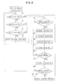
- a flow chart for the turbo compound engine of Figure 1.
- Figure 3 is
- a schematic view showing related art.
- A preferred embodiment of the turbo compound engine of the present invention will be described with reference to the accompanying drawings.
- In Figure 1, reference numeral 1 indicates an engine of a vehicle (not shown), 2 the intake manifold of the
engine 1, and 3 the exhaust manifold of the engine 1. - As depicted in Figure 1, an
exhaust gas passage 4a is connected to theexhaust manifold 3, and to theintake manifold 2 there is connected an intake-air passage 5. Aturbine 10a of theturbocharger 10 is disposed at an intermediate point in theexhaust passage 4a while thecompressor 10b of theturbocharger 10 is disposed in the intake passage 5. In an exhaust passage 4b downstream of theturbocharger 10, apower turbine 12 is disposed for recovering the exhaust gas energy. Afluid passage 25 branches from the exhaust gas passage 4b between thepower turbine 12 and theturbine 10a of theturbocharger 10, and is connected to the passage 4c downstream of thepower turbine 12. At the junction of the passage 4b and thefluid passage 25 upstream of thepower turbine 12, there is provided a passage switching means 30 for closing thefluid passage 25 while throttling the passage 4b to a predetermined degree. The switching means 30 is constructed to have at least two switching positions. Anexternal atmosphere conduit 7 is connected to the exhaust passage 4c connecting thefluid passage 25 to theoutlet port 6 of thepower turbine 12. At the intersection of thepassages 7 and 4c, there is disposed aswitching means 31 which opens the external atmosphere conduit 7 upon closing of the exhaust gas passage 4c. Moreover, anexhaust brake valve 32 is provided in the passage 4b between theswitching valve 30 and theturbine 10a. - In the following, gear trains for connecting the
power turbine 12 to thecrank shaft 15 will be explained. - As shown in Figure 1, an
output gear 16 is disposed at theend 13a of theshaft 13 of thepower turbine 12, andplanetary gears planetary gears ring gear 18 rotating together with aninput pump wheel 21b of afluid coupling 21 provided with alock up mechanism 21a. In other words, theoutput gear 16 is connected to thefluid coupling 21 via theplanetary gear mechanism 19 including theplanetary gears power turbine 12 is transmitted to anoutput pump wheel 21c of thefluid coupling 21. Theepicyclic gear 19 is employed for having a large moderating ratio and a high transmission efficiency To theoutput pump 21c there is fixed agear 20 which rotates with thepump 21c, and to thecrank shaft 15 there is fixed acrank shaft gear 23. - Another
epicyclic gear 40 for connecting thecrank shaft 23 with thegear 20 and for rotating thepower turbine 12 in both normal and reverse senses will be explained. - The
epicylic gear 40 comprises asun gear 41, asun gear shaft 42, aring gear 44 engaged withplanetary gears 43, at intervals in the circumferential direction thereof, and circumferentially surrounding thesun gear 41, and acarrier 45 for maintaining constant the relative positional relationship of theplanetary gear 43 and thesun gear 41 while theplanetary gear 43 rotates autorotationally and revolutionally around thesun gear 41. - The
epicyclic gear 40 will be explained in detail below. - The
sun gear shaft 42 is provided with afirst transmission gear 46 engaged with thecrank shaft gear 23 at one end thereof, and supports saidcarrier 45 by abearing 47 near the other and thereof. On the other hand, thering gear 44 is provided with asecond transmission gear 48 engaged with thegear 20. Thesecond transmission gear 48 includes ahollow shaft 49 housing a part of thesun gear shaft 42 between the first andsecond transmission gears hollow shaft 49 rotates about theshaft 42 and is provided with a oneway clutch 50. The one way clutch connects thefirst transmission gear 46 with theshaft 49 only if drive power is transmitted from thegear 46 to thecrank shaft 15. Thecarrier 45 includes aclutch element 51 extending outwardly in a radial direction The direction of rotation of theepicyclic gear 40 is controlled by hydraulic clutch means 55. In this embodiment, the hydraulic clutch means 55 includes a hydraulic clutch 56 which can be connected to saidclutch element 51 so as to stop thecarrier 45 during the connection mode, a pump 56 supplying oil to the hydraulic clutch 56, avalve 59 disposed in anoil conduit 58 connecting thepump 57 with the hydraulic clutch 56, and acontroller 60 controlling avalve 59. - An ON-OFF signal from a
clutch switch 62 of the engine 1, an ON-OFF signal from anaccelerator switch 63, a rotating speed signal from a rotatingspeed sensor 61 of the engine 1, and a brake control signal from abrake control switch 64 are input into thecontroller 60 while control signals are output from thecontroller 60 to theswitching valves exhaust brake valve 32, theepicyclic gear 19, and thepartition valve 59. Thebrake control switch 64 of the illustrated embodiment has an OFF position, a position 1, and aposition 2. At position 1, thecontroller 60 outputs a command signal to fully close theexhaust brake valve 31 only, whereas atposition 2, same outputs a command signal to close the exhaust passage 4c and to open theair inlet passage 7, a command signal to actuate the switchingvalve 30 of thefluid passage 25 to a predetermined extent for throttling, a command signal to fully close thepartition valve 59 of the hydraulic clutch 56, and a command signal to cancel locking-up of the locking-upmechanism 21a. When thebrake control switch 64 supplies an instruction to thecontroller 60 for OFF position, thecontroller 60 supplies command signals to the switchingvalve 30 for full closing of thefluid passage 25, to the switchingvalve 31 for full closing of theexternal atmosphere duct 7, to the locking-upmechanism 21a for locking-up, and to thevalve 59 for full closing so as to allow the hydraulic clutch 56 to be free from theclutch element 51. - In the following, a control effected by the
controller 60 during deceleration of the vehicle will be described with reference to Figure 2. - In the
controller 60 during normal driving, it will be judged whether theaccelerator switch 63 is OFF atstep 70, whether theclutch switch 62 is ON atstep 71, and whether the engine revolution speed is equal to or higher than 700 r.p.m. atstep 72. When the answers atsteps controller 60 detects that the vehicle is decelerated, and the following steps are executed. First, theexhaust brake valve 32 is fully closed atstep 73 so as to increase the exhaust gas pressure, then it is judged whether thebrake control switch 74 is inposition 2 or not. If the answer atstep 74 is NO, the program returns to step 70, and repeats the above-mentioned procedures. If one of the answers duringsteps 70 through 72 is NO, i.e. thebrake control switch 64 is turned off, the program jumps to step 82. If the answer atstep 74 is YES, thecontroller 60 sends a command signal to the locking-upmechanism 21a of the fluid clutch 21 for eliminating the locking-up as stated in the box labelled 75. Then, the controller sends a command signal to thevalve 30 atstep 76 so that thefluid passage 25 may be throttled to a predetermined extent while sending a signal atstep 77 to thevalve 31 so as to close the exhaust passage 4c and open theexternal atmosphere duct 7. Thepartition valve 59 is closed by a command signal at step 78. - Referring to Figure 1, as the
partition valve 59 is closed, theclutch element 51 and the hydraulic clutch 56 are connected to one another. Thereupon, the drive power of thecrank shaft 15 is transmitted from thecrank shaft gear 23 via thefirst transmission gear 23 and theplanetary gear 43 to thesun gear 41 with the rotation being reversed. After that, the drive power is transmitted from thesun gear 41 to thegear 20 while reversing the rotation again. Then the power is transmitted to theepicyclic gear 19 via thefluid coupling 21. The rotation is reversed at theepicyclic gear 19 and the rotative power is transmitted to thepower turbine 12, so that thepower turbine 12 is rotated in a direction opposite to its own direction during normal driving of the vehicle, whereby air is sucked through theduct 7 and thepower turbine 12 assumes the function of an air compressor. In addition to the normal exhaust brake, energy consumed by compressing the air by the power turbine serves as braking action against the engine 1. Therefore a large braking effort can be applied to the engine 1. At the same time, it is possible to absorb the energy produced when reversing the power turbine by constructing theclutch element 51 and the hydraulic clutch 56 in such a way that sufficient slip may occur between theclutch element 51 and the hydraulic clutch 56. - Referring again to Figure 2, it is checked whether the connection of the hydraulic clutch 56 has lasted three minutes at
step 79. When the answer is NO, steps 75 and 78 are repeated, so that the heat generation in the hydraulic clutch 56 is limited to a predetermined extent and no unduly large braking action is applied to the engine 1. When the answer atstep 79 is YES, the lock-upmechanism 21a starts working. Then, if thebrake control switch 64 is still ON atstep 81, i.e., if thecontrol switch 64 is either inposition 1 or 2, the above-described control for deceleration is repeated. This repetition of deceleration control makes it possible to gradually reduce the engine speed while suppressing load against the hydraulic clutch 56. When the answer atstep 81 is YES, the control for normal driving is performed. More specifically, thecontroller 60 outputs command signals to thevalves fluid line 25 and theair duct 7. Thereupon, thepower turbine 12 starts rotating in normal sense effected by the exhaust gas, so as to recover the energy of the exhaust gas, and the rotative power of normal direction is transmitted to thecrank shaft 15 via the planetary gear 29, and theother gears
Claims (7)
- A turbo compound engine comprising an engine (1) having an output shaft (15), an exhaust gas line (4a, 4b, 4c), a gear train connecting the output shaft (15) of the engine (1) to a power recovering turbine (12) disposed in the exhaust gas line (4b) of the engine (1), and a power reversing mechanism located in the gear train, whereby the power reversing mechanism includes a planetary gear set (40) and whereby a hydraulic slip clutch means (55) is provided in the planetary gear set (40) in a manner such that the hydraulic slip clutch means (55) slippingly connects the output shaft (15) of the engine (1) to the power recovering turbine (12) upon rotational reversal of the power recovering turbine (12) thereby absorbing energy produced upon the rotational reversal of the power recovering turbine (12).
- A turbo compound engine of claim 1, characterized in that said exhaust gas line (4b) has a bypass line (25) bypassing said power recovering turbine (12), an exhaust brake valve (32) is disposed upstream of the bypass line (25), a switch valve (30) is disposed at an intersection of the bypass line (25) and the exhaust gas line (4b) so as to close the exhaust gas line (4b) while opening the bypass line (25) during deceleration of the vehicle, an external atmosphere duct (7) is connected to a part of the exhaust gas line (4c) between the bypass line (25) and the outlet port (6) of the power recovering turbine (12), and a switching valve (31) disposed at said part of the exhaust gas line (4c) so as to close said part of the exhaust gas line (4c) while opening the external atmosphere duct (7).
- A turbo compound engine of claim 1 or 2 characterized in that said power reversing means comprises a sun gear (41), a planetary gear (43) engaged with the sun gear (41), a ring gear (44) having an internal gear (44a) engaged with the planetary gear (43) and an external gear (48) engaged with a gear (20) connected to the power recovering turbine (12), the hydraulic slip clutch means (55) limiting revolution of the planetary gear (43), a transmission gear (46) supported by a hollow shaft (49) rotating with the ring gear (44) via a one way clutch (50) so as to engage with a gear (23) of said output shaft (15) and to rotate with a shaft (42) of the sun gear (41) extending through the hollow shaft (49).
- A turbo compound engine of one of claims 1 through 3, characterized in that said hydraulic clutch means (55) includes a clutch plate (51) attached to a carrier (45) of the planetary gear (43), a further clutch plate coupled with said clutch plate (51), and an actuator (56) coupling and decoupling said two clutch plates with each other based on oil pressure supplied thereto.
- A turbo compound engine according to any one of the foregoing claims, characterized in that the power recovering turbine (12) is disposed in the exhaust gas line (46) downstream of a turbine (10a) of a turbocharger (10) so as to recover energy from the exhaust gas, and that a controller (60) is provided for actuating the exhaust brake valve (32) and the switching valve (31) and for causing the hydraulic slip clutch means (55) to slippingly connect the output shaft (15) with the power recovering turbine (12) upon the rotational reversal of the power recovering turbine (12).
- A turbo compound engine of claim 5, characterized in that said controller (60) is constructed in such fashion that it produces command signals to close the exhaust brake valve (32), to actuate the switching valve (30) disposed in the bypass line (25) and the switching valve (31) disposed downstream of the power recovering turbine (12), and to actuate said hydraulic slip clutch means (55) for coupling.
- A turbo compound engine according to any one of the foregoing claims, characterized in that the hydraulic slip clutch means (55) does not slip for more than three minutes from the connection of the hydraulic slip clutch means (55).
Applications Claiming Priority (2)
| Application Number | Priority Date | Filing Date | Title |
|---|---|---|---|
| JP62188747A JPS6435026A (en) | 1987-07-30 | 1987-07-30 | Turbo compound engine |
| JP188747/87 | 1987-07-30 |
Publications (3)
| Publication Number | Publication Date |
|---|---|
| EP0301547A2 EP0301547A2 (en) | 1989-02-01 |
| EP0301547A3 EP0301547A3 (en) | 1989-08-09 |
| EP0301547B1 true EP0301547B1 (en) | 1992-10-14 |
Family
ID=16229065
Family Applications (1)
| Application Number | Title | Priority Date | Filing Date |
|---|---|---|---|
| EP88112245A Expired - Lifetime EP0301547B1 (en) | 1987-07-30 | 1988-07-28 | Turbo compound engine |
Country Status (5)
| Country | Link |
|---|---|
| US (1) | US4843822A (en) |
| EP (1) | EP0301547B1 (en) |
| JP (1) | JPS6435026A (en) |
| CN (1) | CN1011607B (en) |
| DE (1) | DE3875300T2 (en) |
Families Citing this family (24)
| Publication number | Priority date | Publication date | Assignee | Title |
|---|---|---|---|---|
| US5119633A (en) * | 1990-09-25 | 1992-06-09 | Cummins Engine Company, Inc. | Power turbine bypass for improved compression braking |
| US5142868A (en) * | 1990-11-30 | 1992-09-01 | Cummins Engine Company, Inc. | Turbocompound engine with power turbine bypass control |
| US5474041A (en) * | 1994-12-28 | 1995-12-12 | Cummins Engine Company, Inc. | Engine lubrication system with decreased power draw |
| DE10290840B4 (en) * | 2001-03-01 | 2007-07-26 | Voith Turbo Gmbh & Co. Kg | Drive unit with an internal combustion engine and an exhaust gas turbocharger |
| SE523149C2 (en) * | 2001-08-20 | 2004-03-30 | Volvo Lastvagnar Ab | Turbo engine type combustion engine device |
| DE10339857A1 (en) | 2003-08-29 | 2005-03-24 | Daimlerchrysler Ag | Combustion engine with motor brake system esp in the form of a constant throttle having a bypass unit in the form of a combined switch and throttle valve |
| DE10348967B4 (en) * | 2003-10-22 | 2006-11-02 | Voith Turbo Gmbh & Co. Kg | Method for optimizing the degree of utilization in a drive unit and drive unit |
| DE10360155A1 (en) * | 2003-12-20 | 2005-07-21 | Voith Turbo Gmbh & Co. Kg | Powertrain with exhaust use and control method |
| DE102004002215B3 (en) * | 2004-01-15 | 2005-09-08 | Voith Turbo Gmbh & Co. Kg | Driving force transmission device with hydrodynamic reverse clutch |
| DE102005004058B3 (en) * | 2005-01-28 | 2006-05-24 | Voith Turbo Gmbh & Co. Kg | Turbo compound system with cylinder shaft and exhaust gas turbine |
| US7281872B2 (en) | 2005-10-31 | 2007-10-16 | Hewlett-Packard Development Company, L.P. | Printer |
| US8294946B2 (en) | 2006-06-12 | 2012-10-23 | Hewlett-Packard Development Company, L.P. | Printer |
| BR112012032942A2 (en) * | 2010-06-22 | 2016-11-22 | Volvo Lastvagnar Ab | a composite turbo transmission and a method for controlling a composite turbo transmission |
| US8127544B2 (en) * | 2010-11-03 | 2012-03-06 | Paul Albert Schwiesow | Two-stroke HCCI compound free-piston/gas-turbine engine |
| DE102011012861A1 (en) * | 2011-03-02 | 2012-09-06 | Voith Patent Gmbh | Turbo-compound system, in particular of a motor vehicle |
| JP5969800B2 (en) * | 2012-04-12 | 2016-08-17 | サンデンホールディングス株式会社 | Fluid machinery and Rankine cycle |
| DE102012010348A1 (en) * | 2012-05-25 | 2013-11-28 | GM Global Technology Operations LLC (n. d. Ges. d. Staates Delaware) | Method and device for controlling an electric actuator for a wastegate valve arrangement of an exhaust gas turbocharger |
| US9108628B2 (en) * | 2012-08-31 | 2015-08-18 | GM Global Technology Operations LLC | Turbo compounding hybrid generator powertrain |
| CN103397934A (en) * | 2013-07-04 | 2013-11-20 | 广西玉柴机器股份有限公司 | Internal combustion engine waste gas reuse device |
| ES2605601T3 (en) * | 2013-12-20 | 2017-03-15 | Fpt Motorenforschung Ag | A turbocharged assembly, in particular, for the field of industrial vehicles |
| CN104314695B (en) * | 2014-09-30 | 2016-09-21 | 东风商用车有限公司 | Variable-speed-ratio compound turbine system and application method thereof |
| CN106224086B (en) * | 2016-09-18 | 2018-11-23 | 重庆交通大学 | Hybrid electric vehicle engine waste heat reutilization system |
| US10850860B1 (en) * | 2019-09-09 | 2020-12-01 | Hamiliton Sunstrand Corporation | Internal combustion engines with unidirectional compounding drives |
| CN110485983A (en) * | 2019-09-20 | 2019-11-22 | 烟台杰瑞石油装备技术有限公司 | A kind of turbine pressure break semitrailer |
Citations (2)
| Publication number | Priority date | Publication date | Assignee | Title |
|---|---|---|---|---|
| EP0272680A2 (en) * | 1986-12-26 | 1988-06-29 | Isuzu Motors Limited | Turbo compound engine |
| EP0297287A1 (en) * | 1987-05-30 | 1989-01-04 | Isuzu Motors Limited | Turbo compound engine |
Family Cites Families (6)
| Publication number | Priority date | Publication date | Assignee | Title |
|---|---|---|---|---|
| US2375852A (en) * | 1941-05-17 | 1945-05-15 | Sulzer Ag | Reversible supercharged twostroke internal-combustion engine |
| CH637707A5 (en) * | 1979-06-13 | 1983-08-15 | Rueti Ag Maschf | WEB SHEET FOR A NOZZLE WEAVING MACHINE. |
| JPS57824A (en) * | 1980-05-31 | 1982-01-05 | Matsushita Electric Works Ltd | Breaker with arc gas barrier |
| JPS61921A (en) * | 1984-06-12 | 1986-01-06 | Hitachi Maxell Ltd | Magnetic recording medium |
| US4745755A (en) * | 1985-07-26 | 1988-05-24 | Isuzu Motors Limited | Control system for supercharged internal combustion engine |
| DE3728681A1 (en) * | 1986-08-29 | 1988-03-10 | Isuzu Motors Ltd | TURBO COMPOSITION ENGINE |
-
1987
- 1987-07-30 JP JP62188747A patent/JPS6435026A/en active Granted
-
1988
- 1988-07-28 EP EP88112245A patent/EP0301547B1/en not_active Expired - Lifetime
- 1988-07-28 DE DE8888112245T patent/DE3875300T2/en not_active Expired - Fee Related
- 1988-07-29 CN CN88104535A patent/CN1011607B/en not_active Expired
- 1988-07-29 US US07/226,176 patent/US4843822A/en not_active Expired - Lifetime
Patent Citations (2)
| Publication number | Priority date | Publication date | Assignee | Title |
|---|---|---|---|---|
| EP0272680A2 (en) * | 1986-12-26 | 1988-06-29 | Isuzu Motors Limited | Turbo compound engine |
| EP0297287A1 (en) * | 1987-05-30 | 1989-01-04 | Isuzu Motors Limited | Turbo compound engine |
Also Published As
| Publication number | Publication date |
|---|---|
| JPS6435026A (en) | 1989-02-06 |
| US4843822A (en) | 1989-07-04 |
| CN1031124A (en) | 1989-02-15 |
| CN1011607B (en) | 1991-02-13 |
| EP0301547A3 (en) | 1989-08-09 |
| DE3875300T2 (en) | 1993-04-01 |
| EP0301547A2 (en) | 1989-02-01 |
| JPH0519017B2 (en) | 1993-03-15 |
| DE3875300D1 (en) | 1992-11-19 |
Similar Documents
| Publication | Publication Date | Title |
|---|---|---|
| EP0301547B1 (en) | Turbo compound engine | |
| US4800726A (en) | Turbo compound engine | |
| US4748812A (en) | Turbo compound engine | |
| EP0292010B1 (en) | Engine braking system | |
| JP4325783B2 (en) | Gas turbine, automobile including the gas turbine, and engine brake method for gas turbine | |
| JPH0519018B2 (en) | ||
| US4858440A (en) | Turbo-compound engine | |
| JPH01116229A (en) | Turbo compound engine | |
| JP2522790Y2 (en) | Turbocharger | |
| JP3137802B2 (en) | Engine supercharger | |
| JP3137801B2 (en) | Engine supercharger | |
| JPH0517382B2 (en) | ||
| JPS63289220A (en) | Turbo-compound engine | |
| JPH055230Y2 (en) | ||
| JPH01117940A (en) | Turbocompound engine | |
| JPS6219572B2 (en) | ||
| JPS63111239A (en) | Turbo compound engine | |
| JPH0454221A (en) | Supercharging device for engine | |
| JP3060472B2 (en) | Supercharger for vehicle engine | |
| JPH0637854B2 (en) | Turbo Compound Engine | |
| SU1229395A1 (en) | Combined power plant | |
| JPH0299721A (en) | Engine controller of torque converter loading car | |
| JPH0523392Y2 (en) | ||
| JP2534558Y2 (en) | Hydraulic control device for supercharging system in turbo compound engine | |
| JPH0429061Y2 (en) |
Legal Events
| Date | Code | Title | Description |
|---|---|---|---|
| PUAI | Public reference made under article 153(3) epc to a published international application that has entered the european phase |
Free format text: ORIGINAL CODE: 0009012 |
|
| AK | Designated contracting states |
Kind code of ref document: A2 Designated state(s): AT BE CH DE ES FR GB GR IT LI LU NL SE |
|
| RBV | Designated contracting states (corrected) |
Designated state(s): DE GB |
|
| PUAL | Search report despatched |
Free format text: ORIGINAL CODE: 0009013 |
|
| AK | Designated contracting states |
Kind code of ref document: A3 Designated state(s): DE GB |
|
| 17P | Request for examination filed |
Effective date: 19900103 |
|
| 17Q | First examination report despatched |
Effective date: 19910227 |
|
| GRAA | (expected) grant |
Free format text: ORIGINAL CODE: 0009210 |
|
| AK | Designated contracting states |
Kind code of ref document: B1 Designated state(s): DE GB |
|
| REF | Corresponds to: |
Ref document number: 3875300 Country of ref document: DE Date of ref document: 19921119 |
|
| PLBE | No opposition filed within time limit |
Free format text: ORIGINAL CODE: 0009261 |
|
| 26N | No opposition filed | ||
| REG | Reference to a national code |
Ref country code: GB Ref legal event code: IF02 |
|
| PGFP | Annual fee paid to national office [announced via postgrant information from national office to epo] |
Ref country code: GB Payment date: 20050615 Year of fee payment: 18 |
|
| PGFP | Annual fee paid to national office [announced via postgrant information from national office to epo] |
Ref country code: DE Payment date: 20050617 Year of fee payment: 18 |
|
| PG25 | Lapsed in a contracting state [announced via postgrant information from national office to epo] |
Ref country code: GB Free format text: LAPSE BECAUSE OF NON-PAYMENT OF DUE FEES Effective date: 20060728 |
|
| PG25 | Lapsed in a contracting state [announced via postgrant information from national office to epo] |
Ref country code: DE Free format text: LAPSE BECAUSE OF NON-PAYMENT OF DUE FEES Effective date: 20070201 |
|
| GBPC | Gb: european patent ceased through non-payment of renewal fee |
Effective date: 20060728 |