EP0300937B1 - Haymaking machine equipped with several pivoting raking wheels in order to be folded up for transport or storage - Google Patents
Haymaking machine equipped with several pivoting raking wheels in order to be folded up for transport or storage Download PDFInfo
- Publication number
- EP0300937B1 EP0300937B1 EP88440054A EP88440054A EP0300937B1 EP 0300937 B1 EP0300937 B1 EP 0300937B1 EP 88440054 A EP88440054 A EP 88440054A EP 88440054 A EP88440054 A EP 88440054A EP 0300937 B1 EP0300937 B1 EP 0300937B1
- Authority
- EP
- European Patent Office
- Prior art keywords
- lateral
- pivot
- raking
- machine according
- haymaking machine
- Prior art date
- Legal status (The legal status is an assumption and is not a legal conclusion. Google has not performed a legal analysis and makes no representation as to the accuracy of the status listed.)
- Expired - Lifetime
Links
Images


Classifications
-
- A—HUMAN NECESSITIES
- A01—AGRICULTURE; FORESTRY; ANIMAL HUSBANDRY; HUNTING; TRAPPING; FISHING
- A01D—HARVESTING; MOWING
- A01D78/00—Haymakers with tines moving with respect to the machine
- A01D78/08—Haymakers with tines moving with respect to the machine with tine-carrying rotary heads or wheels
- A01D78/10—Haymakers with tines moving with respect to the machine with tine-carrying rotary heads or wheels the tines rotating about a substantially vertical axis
- A01D78/1007—Arrangements to facilitate transportation specially adapted therefor
- A01D78/1014—Folding frames
-
- A—HUMAN NECESSITIES
- A01—AGRICULTURE; FORESTRY; ANIMAL HUSBANDRY; HUNTING; TRAPPING; FISHING
- A01D—HARVESTING; MOWING
- A01D75/00—Accessories for harvesters or mowers
- A01D75/20—Devices for protecting men or animals
- A01D2075/203—Devices for protecting men or animals by stopping driving when lifting frames, e.g. for haymakers
Definitions
- the present invention relates to a haymaking machine comprising in particular an elongated support frame which carries several raking wheels which can be driven in rotation during work around axes directed upwards, said frame consisting of a central part supporting wheels central raking machines and two lateral parts each supporting at least one lateral raking wheel.
- Said lateral parts are articulated to the central part by means of pivots substantially parallel to the direction of advance of the machine, around which they can pivot in order to follow the unevenness of the ground and can be moved by means of operating devices for the purpose of transport or storage, each of these lateral parts comprising an articulation for tilting the lateral raking wheel, this articulation being situated between the corresponding pivot and the axis of rotation of the lateral raking wheel which is closest to said pivot and means of blocking of this articulation when the raking wheels are unfolded in the working position.
- a machine of this kind known in patent application EP-A-203023 comprises a support frame of elongated shape, consisting of a central part and two lateral parts which are articulated at the ends of said central part by means of pivots substantially horizontal.
- This central part is itself constituted by two substantially parallel beams which are interconnected by means of plates. To the upper beam is connected a connecting beam which extends substantially perpendicular to the chassis and the other end of which carries a coupling trestle.
- This coupling bridge is provided with three coupling points used to attach the machine to the three-point coupling device of a drive tractor.
- the central part of the chassis can carry two raking wheels, while each of the lateral parts carries a raking wheel.
- Said wheels are located directly under the central part and the lateral parts of the chassis. They are all substantially identical.
- Each is constituted by a hub to which are fixed several arms carrying working forks at their outer ends.
- Each hub is mounted so that it can rotate on a fixed axis which is substantially vertical or inclined in the direction of advance of the machine. These axes are connected to the chassis and carry rollers at their lower ends allowing the machine to be moved on the ground during work.
- the four raking wheels are substantially aligned. They are rotated in a manner known per se from the PTO shaft of the drive tractor.
- drive shafts provided with pinions which cooperate with toothed rings connected to the hub, are housed in the parts of the chassis.
- the raking wheels then rotate two by two in convergence at the front - seen in the direction of travel -. As a result of this rotation, their forks move the forage and ensure excellent tedding. It is obvious that raking wheels intended for making swaths or that can carry out both tedding and swathing can be provided on this machine.
- the outer parts of the chassis can be moved upwards by an angle of about 90 ° around the pivots in order to reduce the size of the machine.
- the displacement of each of these parts is advantageously ensured by means of a hydraulic cylinder.
- Each cylinder is articulated to the central part of the chassis by means of an axis and to the corresponding lateral part also by means of an axis.
- the actuation of these cylinders is advantageously done from the tractor. They can be double or single acting. In the latter case, the lateral parts return to the working position under the effect of their own weight.
- the drive shafts of the outer raking wheels have articulations at the pivots, so that they can pivot with the lateral parts of the chassis.
- the width of the machine is therefore reduced compared to the working position.
- its size is still relatively large especially for travel on the roads or for storage.
- the working forks of the raking wheels are directed outwards. They can thus cause significant damage or injury to anything that, for example vehicles, people or animals, can collide with them both during travel and when stopped.
- each raking wheel which is attached to a lateral part of the chassis above the central part of the chassis. This position is obtained by rotating said raking wheel by an angle of about 180 ° around the aforementioned pivot axis.
- this embodiment if it makes it possible to achieve the desired result, is relatively complex and uses numerous guide parts so that said pivoting of approximately 180 ° takes place automatically when the outer raking wheels are raised in transport position.
- the center of gravity of the machine remains fairly high. This affects the stability of the machine, especially when it is detached from the tractor and placed on the ground, and practically prevents the production of machines with more than four raking wheels.
- Patent application DE-A-1782632 relates to a machine with four raking wheels supported by a chassis which is produced in two parts hinged together through an intermediate piece. For transport, one of these parts can be tilted above the other, around the joints of the intermediate piece. This movement must be done manually by an operator, which requires significant effort. In addition, the risk to the operator is considerable due to the size of the raking wheels and the presence of forks on them.
- Patent application EP-A-288416 (document belonging to the state of the art defined according to Article 54 (3) of the EPC, for the contracting states designated AT, DE, FR and NL) relates to a machine with four raking wheels supported by a chassis comprising a central part and two lateral parts. Each of these lateral parts can be lifted relative to the central part and has an articulation for tilting the raking wheel which it carries, above the central part. This movement requires hydraulic cylinders for lifting and specific connecting rods for said tilting. These various means complicate the machine and cause it to become more expensive.
- the general problem to be solved by the subject of the present application is to make a machine on which the size and the risk incurred by the neighborhood during transport and storage can be reduced safely, while being both simple , inexpensive and stable.
- this problem is solved in that the axis of rotation of the articulation is substantially parallel to the pivot axis of the pivot and substantially perpendicular to the longitudinal axis of the lateral part, and that each device for maneuver to move the lateral parts of the chassis is fixed to the central part of the chassis and to the portion of said lateral part which is located beyond the articulation around which the lateral raking wheel or wheels rock, that is to say say between this articulation and the lateral raking wheel which is closest to the pivot of each lateral part on the central part of the chassis or on this lateral raking wheel, or even beyond this lateral raking wheel.
- the operating device directly generates the tilting and folding of the lateral raking wheel (s) when the corresponding lateral part of the chassis is moved in height relative to the central part of the frame.
- the frame (2) consists of a central part (9) and two lateral parts (1) connected to the ends of said central part by means of pivots (4).
- Each of the two lateral parts (1) of the chassis (2) has a hinge (3) located between the pivot (4), around which the lateral part (1) can be moved relative to the central part (9), and the axis of rotation (5Z) of the raking wheel (5) which is on the lateral part (1) and which is closest to said pivot (4), so as to allow the tilting of the wheel (s) rakeers (5) and / or (6) fixed to this lateral part (1), when the latter is moved in height relative to the central part (9) of the chassis (2).
- the axis of rotation (3Y) of the articulation (3) is substantially parallel to the pivot axis (4Y) of the pivot (4) and substantially perpendicular to the longitudinal axis (1X) of the lateral part (1) , therefore parallel to the direction of advance of the machine, the articulation (3) being located in the immediate vicinity of the axis of rotation (5Z) of the raking wheel (5).
- the machine has four raking wheels, two of which (7) are fixed to the central part (9) of the chassis (2) and the other two (5) each on one of the two lateral parts (1) of the chassis (2), in this case at the end of each lateral part (1), the assembly being symmetrical with respect to the longitudinal axis of the machine.
- an operating device (10) for lifting the part lateral (1) is located above this lateral part (1) and is fixed to the central part (9) and to the portion of said lateral part (1) situated beyond the articulation (3), c '' i.e. between the articulation (3) and the raking wheel (5) or on the raking wheel (5) itself, or even beyond this raking wheel (5), so as to generate directly the tilting and folding of the raking wheel (5) when the side part is moved in height by pivoting around the pivot (4).
- the operating device (10) is advantageously fixed to a cover located above the hub (11) of the wheel (5).
- the end of the telescopic part (10A) of the operating device (10) is provided with a lug (26) sliding in an oblong orifice (27) with tabs integral with the lateral part (1), so to be able to compensate for the angular variations of the lateral part (1) due to the unevenness of the ground.
- the pivot (4) allows the lateral part (1) to follow the unevenness of the ground transmitted by the wheels (30) of the machine.
- the central part (9) and the lateral part (1) of the chassis (2) are provided with stops whose position allows an angular movement of said lateral part (1) of about 10 ° towards the bottom.
- This clearance allows the raking wheel (5) disposed at the end of the side part (1) to move downward relative to the central part (9).
- the articulation (3) is in particular blocked by means of two stops (24, 25) arranged under the articulation (3) and by means of a locking device (17) in the form of a hook (18) capable of pivot about a central axis of rotation (18Y), cooperating with a stop (19) and being connected to a return spring (20).
- This blocking is important so that the raking wheels (5) of the side parts (1) remain stable during work. It prevents them from tilting around the joints (3) both when the machine is moved on the ground or when it is temporarily lifted, for example at the end of the ground.
- the fixing element (10Y) of the operating device (10) is provided with a bent lug (21) arranged in such a way that when the telescopic part (10A) is in movement for move the lateral part (1) to the transport position, it abuts against the upper end of the hook (18) and thus drives it in rotation around the axis (18Y), causing it to be automatically unlocked (see Figures 6 and 7 ).
- the upper end of the hook (18) is connected to a cable (22) guided through an eyelet (23), so as to allow manual unlocking of the hook (18) (see figures 4 and 5).
- the angular movement of the raking wheel (5) in the working position is compensated by the oblong opening (27), the length of which is calculated so that it does not hamper an angular movement of about 10 ° towards the down and up.
- the raking wheel (5) can freely follow the unevenness of the ground without transmitting them to the operating device (10).
- the haymaking machine therefore works as if the joint (3) did not exist.
- the operating device (10) is actuated advantageously in the form of a hydraulic cylinder provided with two telescopic arms (10A) and (10B), after having unlocked the device. (17) by actuating the cable (22), for example, from the driver's seat, in the direction indicated by the arrow (F) (see Figure 4).
- this unlocking can also be done automatically thanks to the bent lug (21) arranged so that before it reaches the end of its travel in the oblong opening (27), it abuts against the upper end of the hook (18) in order to rotate it and thus cause unlocking (see Figures 6 and 7).
- the jack (10) initially causes the lifting of the raking wheel (5) which swings around the articulation (3). Then, the side part (1) folds around the pivot (4).
- the machine in the transport or storage position is shown in figure (3).
- the raking wheel (5) has thus tilted at an angle of approximately 180 ° relative to its working position and is found substantially upside down. In this position its forks are directed upwards and not outwards.
- this raking wheel (5) approaches the central part (9) of the chassis (2).
- this raking wheel (5) remains maintained in this position thanks to the jack (10).
- the operating device (10) is fixed to the portion of the lateral part (1) located not beyond the joint (3 ), but between the articulation (3) and the pivot (4) so as to cause the tilting wheel (5) to tilt and fold down under the effect of its own weight when the side part is moved in height by pivoting around the pivot (4).
- the articulation (3) is unlocked manually by actuating the cable (22) in the direction indicated by the arrow (F) (see FIGS. 10 and 11).
- the side part (1) pivots around the pivot (4).
- the raking wheel (5) swings down around the joint (3), under the effect of its own weight, by an additional angle of approximately 90 ° up to that two stops (31 and 32) located above the joint (3) are in contact with each other.
- the machine has six raking wheels, two of which (7) are fixed to the central part (9) of the chassis (2), and the other four in pairs (5 and 6) respectively on each of the two lateral parts (1) of the chassis (2), the assembly being perfectly symmetrical with respect to the longitudinal axis of the machine.
- each side part (1) is produced in two portions linked together by a pivot (12).
- the operating device (10) is located above the lateral part (1) and is fixed to the central part (9) and to the portion of said lateral part (1) situated beyond the pivot (12) lying between the articulation (3) and the axis of rotation (6Z) of the raking wheel (6), that is to say -display between the pivot (12) and the raking wheel (6) or on the raking wheel (6) itself, or even beyond this raking wheel (6), so as to directly cause the tilting and folding of raking wheels (5 and 6) when the lateral part (1) is moved in height by pivoting around the pivot (4).
- the pivots (4 and 12) allow the lateral part (1) to follow the unevenness of the ground transmitted by the wheels (30) of the machine.
- the central part (9) and the lateral part (1) of the chassis (2) comprise at (34) stops the position of which allows an angular movement downwards of approximately 10 °.
- These rods (38) are articulated at (40) in lugs (44) integral with the intermediate part (1) and in (39) in oblong holes (33) with lugs (43) integral with the outer part (1) of the chassis (2).
- the angular movement of said outer part of the chassis with the raking wheel (6) is defined by the oblong holes (33).
- the value of the angle of travel around the pivot (12) is approximately 20 ° (10 ° in each direction).
- the two joints (39, 40) are located substantially above the pivot (12) and the joint (3).
- Said articulation (3) is also locked in the working position thanks to the device (17) and completely blocked thanks to the two stops (24, 25) arranged under the articulation (3).
- the device (17) When it comes to putting the machine in the transport or storage position, the device (17) is manually unlocked using the cable (22), then the cylinder (10). The latter initially causes the lifting of the raking wheel (6) which swings around the pivot (12) until the rods (38) arrive at the end of their travel in the oblong orifices (33). Then, in a second step, the raking wheel (5) pivots around the articulation (3) until the two stops (35 and 36) located above the articulation (3) are in contact.
- the two rods (38) push the outer part (1) with the raking wheel (6) in a reverse rotation around the pivot (12), so that the raking wheel (6) pivots until the two stops (41 and 42) located below the pivot (12) are in contact.
- the intermediate part (1) then pivots around the pivot (4) by an angle of approximately 90 °.
- the machine in the transport or storage position is shown in Figure (13).
- the raking wheel (6) is found in a more or less vertical position, while the raking wheel (5) has rotated about 180 ° relative to its working position and is found upside down.
- the actuator (10) at the end of the race maintains the assembly in this position.
- the tilting of the other two raking wheels located on the other lateral part of the machine was carried out simultaneously and according to the same principle, so that the four raking wheels are in the folded position.
- the two outer raking wheels (6) of each side part (1) may touch each other. Therefore, it may be advantageous to provide the cover of the hub (11) of these raking wheels of a pad (8) of protection, also allowing better stabilization of the assembly.
- the forks of the raking wheels (5 and 6) are not dangerous, the height of the machine is reduced and the center of gravity lowered, due to the downward pivoting of the raking wheel (5) around the articulation (3).
- the operating device (10) is fixed to the portion of the lateral part (1) situated not beyond the pivot (12), but on the hub cover (11) of the wheel (5).
- said hub cover (11) of the wheel (5) has a lateral part (13) provided with a slot in which is guided a lug (26) of the operating device (10) .
- a bent piece (14) is connected to the lug (26) of the operating device (10).
- This part (14) has a slot (15) in which slides a lug (16) fixed on the part (1) carrying the raking wheel (6), near the pivot (12).
- the part (14) is moved and drives the lug (16) as soon as it is in contact with the lower end of the slot (15) in which it slides. Then, firstly, the raking wheel (5) swings up around the articulation (3) and the raking wheel (6) rotates around the pivot (12). The lug (16) then slides in the slot (15) of the part angled (14) until it stops at the upper end of said slot (15). The pivoting around the pivot (12) is then blocked, the raking wheel (6) having reached its folded position. The raking wheel (5) then continues to rock around the articulation (3) until the two stops (35 and 36) located above the articulation (3) come into contact. The side part (1) then pivots around the pivot (4) by an angle of approximately 90 ° and the machine reaches its transport or storage position as shown in Figure 15 of the accompanying drawings.
- the raking wheels (5 and 6) are in a position substantially identical to that indicated above (see Figure 13).
- the drive of the raking wheels (5 and 6) is offset by positioning the pinions, so that they do not touch in the folded position, their tools never coming into contact with each other, nor with the wheels. (30) of the machine.
- the machine can be provided with an automatic declutching device (28) of an electromagnetic transmission provided between the drive means going from the tractor to machine.
- This device provides instant disengagement of the drive when the side part (1) is lifted for tilting the raking wheels (5 and / or 6).
- the declutching device (28) could be, for example, in the form of a push button (29) disposed on the telescopic part (10B) of the control device (10), the telescopic part (10A) comprising a rod ( 37) which, when the control device (10) is actuated, slides on the telescopic part (10B) and comes into contact with the push button (29) which it actuates, thus causing an instantaneous disengagement.
- This declutching device (28) can be adapted to all types of machines described in the present invention. It has been shown, by way of nonlimiting example, in FIG. 16 of the appended drawings on the type of machine with six raking wheels represented in FIG. 14.
- the transmission will, of course, be provided with different articulations, preferably with cardan joints, arranged at the same height as the different pivots and articulations of the lateral parts (1).
Abstract
Description
La présente invention concerne une machine de fenaison comportant notamment un châssis support de forme allongée qui porte plusieurs roues râteleuses pouvant être entraînées en rotation durant le travail autour d'axes dirigés vers le haut, ledit châssis se composant d'une partie centrale supportant des roues râteleuses centrales et de deux parties latérales supportant chacune au moins une roue râteleuse latérale. Lesdites parties latérales sont articulées à la partie centrale au moyen de pivots sensiblement parallèles au sens d'avancement de la machine, autour desquels elles peuvent pivoter en vue de suivre les inégalités du sol et peuvent être déplacées au moyen de dispositifs de manoeuvre en vue du transport ou du remisage, chacune de ces parties latérales comportant une articulation pour basculer la roue râteleuse latérale, cette articulation étant située entre le pivot correspondant et l'axe de rotation de la roue râteleuse latérale qui est la plus proche dudit pivot et des moyens de blocage de cette articulation lorsque les roues râteleuses sont dépliées en position de travail.The present invention relates to a haymaking machine comprising in particular an elongated support frame which carries several raking wheels which can be driven in rotation during work around axes directed upwards, said frame consisting of a central part supporting wheels central raking machines and two lateral parts each supporting at least one lateral raking wheel. Said lateral parts are articulated to the central part by means of pivots substantially parallel to the direction of advance of the machine, around which they can pivot in order to follow the unevenness of the ground and can be moved by means of operating devices for the purpose of transport or storage, each of these lateral parts comprising an articulation for tilting the lateral raking wheel, this articulation being situated between the corresponding pivot and the axis of rotation of the lateral raking wheel which is closest to said pivot and means of blocking of this articulation when the raking wheels are unfolded in the working position.
Une machine de ce genre, connue dans la demande de brevet EP-A-203023 comporte un châssis support de forme allongée, constitué d'une partie centrale et de deux parties latérales qui sont articulées aux extrémités de ladite partie centrale au moyen de pivots sensiblement horizontaux.A machine of this kind, known in patent application EP-A-203023 comprises a support frame of elongated shape, consisting of a central part and two lateral parts which are articulated at the ends of said central part by means of pivots substantially horizontal.
Cette partie centrale est elle-même constituée par deux longerons sensiblement parallèles et qui sont reliés entre eux au moyen de plaques. Au longeron supérieur est reliée une poutre de liaison qui s'étend sensiblement perpendiculairement au châssis et dont l'autre extrémité porte un chevalet d'attelage. Ce chevalet d'attelage est muni de trois points d'accouplement servant à fixer la machine au dispositif d'attelage trois points d'un tracteur d'entraînement.This central part is itself constituted by two substantially parallel beams which are interconnected by means of plates. To the upper beam is connected a connecting beam which extends substantially perpendicular to the chassis and the other end of which carries a coupling trestle. This coupling bridge is provided with three coupling points used to attach the machine to the three-point coupling device of a drive tractor.
La partie centrale du châssis peut porter deux roues râteleuses, tandis que chacune des parties latérales porte une roue râteleuse. Lesdites roues se situent directement sous la partie centrale et les parties latérales du châssis. Elles sont toutes sensiblement identiques. Chacune est constituée par un moyeu auquel sont fixés plusieurs bras portant des fourches de travail à leurs extrémités extérieures. Chaque moyeu est monté de manière à pouvoir tourner sur un axe fixe sensiblement vertical ou incliné dans la direction d'avancement de la machine. Ces axes sont reliés au châssis et portent à leurs extrémités inférieures des roulettes permettant de déplacer la machine sur le sol durant le travail.The central part of the chassis can carry two raking wheels, while each of the lateral parts carries a raking wheel. Said wheels are located directly under the central part and the lateral parts of the chassis. They are all substantially identical. Each is constituted by a hub to which are fixed several arms carrying working forks at their outer ends. Each hub is mounted so that it can rotate on a fixed axis which is substantially vertical or inclined in the direction of advance of the machine. These axes are connected to the chassis and carry rollers at their lower ends allowing the machine to be moved on the ground during work.
Dans la position de travail, les quatre roues râteleuses sont sensiblement alignées. Elles sont entraînées en rotation d'une manière connue en soi à partir de l'arbre de prise de force du tracteur d'entraînement. A cet effet, des arbres d'entraînement munis de pignons qui coopèrent avec des couronnes dentées reliées au moyeux, sont logés dans les parties du châssis. Les roues râteleuses tournent alors deux par deux en convergence à l'avant ― vu dans le sens d'avancement ―. Par suite de cette rotation, leurs fourches déplacent le fourrage et assurent un fanage d'excellente qualité. Il est bien évident que des roues râteleuses destinées à effectuer des andains ou bien pouvant réaliser à la fois le fanage et l'andainage, peuvent être prévues sur cette machine.In the working position, the four raking wheels are substantially aligned. They are rotated in a manner known per se from the PTO shaft of the drive tractor. To this end, drive shafts provided with pinions which cooperate with toothed rings connected to the hub, are housed in the parts of the chassis. The raking wheels then rotate two by two in convergence at the front - seen in the direction of travel -. As a result of this rotation, their forks move the forage and ensure excellent tedding. It is obvious that raking wheels intended for making swaths or that can carry out both tedding and swathing can be provided on this machine.
Pour le transport ou le remisage, les parties extérieures du châssis peuvent être déplacées vers le haut d'un angle d'environ 90° autour des pivots en vue de réduire l'encombrement de la machine. Le déplacement de chacune de ces parties est avantageusement assuré au moyen d'un vérin hydraulique. Chaque vérin est articulé à la partie centrale du châssis au moyen d'un axe et à la partie latérale correspondante également au moyen d'un axe. L'actionnement de ces vérins se fait avantageusement à partir du tracteur. Ils peuvent être à double ou à simple effet. Dans ce dernier cas, le retour des parties latérales dans la position de travail se fait sous l'effet de leur propre poids. Les arbres d'entraînement des roues râteleuses extérieures comportent des articulations au niveau des pivots, de manière à pouvoir pivoter avec les parties latérales du châssis.For transport or storage, the outer parts of the chassis can be moved upwards by an angle of about 90 ° around the pivots in order to reduce the size of the machine. The displacement of each of these parts is advantageously ensured by means of a hydraulic cylinder. Each cylinder is articulated to the central part of the chassis by means of an axis and to the corresponding lateral part also by means of an axis. The actuation of these cylinders is advantageously done from the tractor. They can be double or single acting. In the latter case, the lateral parts return to the working position under the effect of their own weight. The drive shafts of the outer raking wheels have articulations at the pivots, so that they can pivot with the lateral parts of the chassis.
Dans la position de transport ou de remisage, la largeur de la machine est donc réduite par rapport à la position de travail. Toutefois, son encombrement est encore relativement important surtout pour les déplacements sur les routes ou pour le remisage. D'autre part, dans cette position relevée, les fourches de travail des roues râteleuses sont dirigées vers l'extérieur. Elles peuvent ainsi causer d'importants dégâts ou blessures à tout ce qui, comme par exemple des véhicules, des hommes ou des animaux, peut entrer en collision avec elles aussi bien lors des déplacements qu'à l'arrêt.In the transport or storage position, the width of the machine is therefore reduced compared to the working position. However, its size is still relatively large especially for travel on the roads or for storage. On the other hand, in this raised position, the working forks of the raking wheels are directed outwards. They can thus cause significant damage or injury to anything that, for example vehicles, people or animals, can collide with them both during travel and when stopped.
On a alors pensé à pourvoir chaque partie latérale du châssis de la machine d'un axe de pivotement permettant de modifier la position de la roue râteleuse qui est fixée à cette partie latérale lorsque celle-ci est déplacée autour du pivot la reliant à la partie centrale du châssis.We then thought of providing each lateral part of the chassis of the machine with a pivot axis making it possible to modify the position of the raking wheel which is fixed to this lateral part when the latter is moved around. of the pivot connecting it to the central part of the chassis.
Ainsi, il est possible d'amener chaque roue râteleuse qui est rattachée à une partie latérale du châssis au-dessus de la partie centrale du châssis. Cette position est obtenue en faisant tourner ladite roue râteleuse d'un angle d'environ 180° autour de l'axe de pivotement précité.Thus, it is possible to bring each raking wheel which is attached to a lateral part of the chassis above the central part of the chassis. This position is obtained by rotating said raking wheel by an angle of about 180 ° around the aforementioned pivot axis.
Mais ce mode de réalisation, s'il permet d'atteindre le résultat souhaité, est relativement complexe et fait appel à de nombreuses pièces de guidage pour que ledit pivotement d'environ 180° s'effectue automatiquement lorsque les roues râteleuses extérieures sont relevées en position de transport. En sus, dans la position de transport et/ou de remisage le centre de gravité de la machine reste assez élevé. Ceci nuit à la stabilité de la machine notamment lorsqu'elle est détachée du tracteur et déposée au sol, et empêche pratiquement la réalisation de machines avec plus que quatre roues râteleuses.However, this embodiment, if it makes it possible to achieve the desired result, is relatively complex and uses numerous guide parts so that said pivoting of approximately 180 ° takes place automatically when the outer raking wheels are raised in transport position. In addition, in the transport and / or storage position the center of gravity of the machine remains fairly high. This affects the stability of the machine, especially when it is detached from the tractor and placed on the ground, and practically prevents the production of machines with more than four raking wheels.
La demande de brevet DE-A-1782632 se rapporte à une machine à quatre roues râteleuses supportées par un châssis qui est réalisé en deux parties articulées entre elles à travers une pièce intermédiaire. Pour le transport, l'une de ces parties peut être basculée au-dessus de l'autre, autour des articulations de la pièce intermédiaire. Ce déplacement doit être effectué manuellement par un opérateur, ce qui demande un important effort. De plus, le risque encouru par l'opérateur est considérable en raison de la taille des roues râteleuses et de la présence de fourches sur ces dernières.Patent application DE-A-1782632 relates to a machine with four raking wheels supported by a chassis which is produced in two parts hinged together through an intermediate piece. For transport, one of these parts can be tilted above the other, around the joints of the intermediate piece. This movement must be done manually by an operator, which requires significant effort. In addition, the risk to the operator is considerable due to the size of the raking wheels and the presence of forks on them.
La demande de brevet EP-A-288416 (document appartenant à l'état de la technique défini selon l'article 54(3) de la CBE, pour les états contractants désignés AT, DE, FR et NL) se rapporte à une machine à quatre roues râteleuses supportées par un châssis comportant une partie centrale et deux parties latérales. Chacune de ces parties latérales est relevable par rapport à la partie centrale et, comporte une articulation pour basculer la roue râteleuse qu'elle porte, au-dessus de la partie centrale. Ce déplacement nécessite des vérins hydrauliques pour le relevage et des bielles spécifiques pour ledit basculement. Ces différents moyens compliquent la machine et provoquent un renchérissement de cette dernière.Patent application EP-A-288416 (document belonging to the state of the art defined according to Article 54 (3) of the EPC, for the contracting states designated AT, DE, FR and NL) relates to a machine with four raking wheels supported by a chassis comprising a central part and two lateral parts. Each of these lateral parts can be lifted relative to the central part and has an articulation for tilting the raking wheel which it carries, above the central part. This movement requires hydraulic cylinders for lifting and specific connecting rods for said tilting. These various means complicate the machine and cause it to become more expensive.
Le problème général à résoudre par l'objet de la présente demande est de réaliser une machine sur laquelle l'encombrement et le risque encouru par le voisinage durant le transport et le remisage peuvent être réduits en toute sécurité, tout en étant à la fois simple, peu onéreuse et stable.The general problem to be solved by the subject of the present application is to make a machine on which the size and the risk incurred by the neighborhood during transport and storage can be reduced safely, while being both simple , inexpensive and stable.
Selon la présente invention, ce problème est résolu en ce que l'axe de rotation de l'articulation est sensiblement parallèle à l'axe de pivotement du pivot et sensiblement perpendiculaire à l'axe longitudinal de la partie latérale, et que chaque dispositif de manoeuvre pour déplacer les parties latérales du châssis est fixé à la partie centrale du châssis et à la portion de ladite partie latérale qui est située au-delà de l'articulation autour de laquelle bascule la ou les roues râteleuses latérales, c'est-à-dire entre cette articulation et la roue râteleuse latérale qui est la plus proche du pivot de chaque partie latérale sur la partie centrale du châssis ou sur cette roue râteleuse latérale, ou encore au-delà de cette roue râteleuse latérale. De cette manière, le dispositif de manoeuvre engendre directement le basculement et le repliement de la ou des roues râteleuses latérales lorsque la partie latérale correspondante du châssis est déplacée en hauteur par rapport à la partie centrale du châssis.According to the present invention, this problem is solved in that the axis of rotation of the articulation is substantially parallel to the pivot axis of the pivot and substantially perpendicular to the longitudinal axis of the lateral part, and that each device for maneuver to move the lateral parts of the chassis is fixed to the central part of the chassis and to the portion of said lateral part which is located beyond the articulation around which the lateral raking wheel or wheels rock, that is to say say between this articulation and the lateral raking wheel which is closest to the pivot of each lateral part on the central part of the chassis or on this lateral raking wheel, or even beyond this lateral raking wheel. In this way, the operating device directly generates the tilting and folding of the lateral raking wheel (s) when the corresponding lateral part of the chassis is moved in height relative to the central part of the frame.
L'invention sera mieux comprise grâce à la description ci-après, qui se rapporte à différents modes de réalisation, donnés à titre d'exemples non limitatifs, et expliqués avec référence aux dessins schématiques annexés, dans lesquels:
- ― la figure 1 est une vue partielle de face de la machine conforme à un premier mode de réalisation de l'invention et pourvue de quatre roues râteleuses, en position de travail;
- ― la figure 2 est une vue partielle de dessus, à plus grande échelle, de la machine conforme à l'invention;
- ― la figure 3 est une vue partielle de face de la machine, en position de transport ou de remisage;
- ― la figure 4 est une vue partielle de face, à plus grande échelle, du dispositif de verrouillage de la machine en position de travail;
- ― la figure 5 est une vue partielle de face, à plus grande échelle, du dispositif de verrouillage de la machine en position de transport et de remisage;
- ― la figure 6 est une vue partielle de face, à plus grande échelle, d'une variante du dispositif de verrouillage de la machine, en position de travail et à l'état verrouillé;
- ― la figure 7 est une vue partielle de face, à plus grande échelle, du dispositif de verrouillage représenté à la figure 6, en position de travail et à l'état déverrouillé;
- ― la figure 8 est une vue partielle de face d'une variante de réalisation de la machine, en position de travail;
- ― la figure 9 est une vue partielle de face de la machine représentée à la figure 8, en position de transport ou de remisage;
- ― la figure 10 est une vue partielle de face, à plus grande échelle, du dispositif de verrouillage de la machine représentée à la figure 8, en position de travail;
- ― la figure 11 est une vue partielle de face, à plus grande échelle, du dispositif de verrouillage de la machine en position de transport ou de remisage;
- ― la figure 12 est une vue partielle de face de la machine conforme à un second mode de réalisation de l'invention et pourvue de six roues râteleuses, en position de travail;
- ― la figure 13 est une vue partielle de face de la machine représentée à la figure 12, en position de transport ou de remisage;
- ― la figure 14 est une vue partielle de face d'une variante de réalisation de la machine en position de travail;
- ― la figure 15 est une vue partielle de face de la machine représentée à la figure 14, en position de transport ou de remisage, et
- ― la figure 16 est une vue partielle de face de la machine représentée à la figure 12, et munie d'un dispositif de débrayage automatique.
- - Figure 1 is a partial front view of the machine according to a first embodiment of the invention and provided with four raking wheels, in the working position;
- - Figure 2 is a partial top view, on a larger scale, of the machine according to the invention;
- - Figure 3 is a partial front view of the machine, in the transport or storage position;
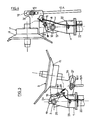
- - Figure 4 is a partial front view, on a larger scale, of the machine locking device in the working position;
- - Figure 5 is a partial front view, on a larger scale, of the machine locking device in the transport and storage position;
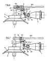
- - Figure 6 is a partial front view, on a larger scale, of a variant of the machine locking device, in the working position and in the locked state;
- - Figure 7 is a partial front view, on a larger scale, of the locking device shown in Figure 6, in the working position and in the unlocked state;
- - Figure 8 is a partial front view of an alternative embodiment of the machine, in the working position;
- - Figure 9 is a partial front view of the machine shown in Figure 8, in the transport or storage position;
- - Figure 10 is a partial front view, on a larger scale, of the machine locking device shown in Figure 8, in the working position;
- - Figure 11 is a partial front view, on a larger scale, of the machine locking device in the transport or storage position;
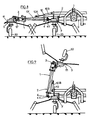
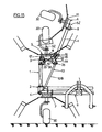
- - Figure 12 is a partial front view of the machine according to a second embodiment of the invention and provided with six raking wheels, in the working position;
- - Figure 13 is a partial front view of the machine shown in Figure 12, in the transport or storage position;
- - Figure 14 is a partial front view of an alternative embodiment of the machine in the working position;
- FIG. 15 is a partial front view of the machine shown in FIG. 14, in the transport or storage position, and
- - Figure 16 is a partial front view of the machine shown in Figure 12, and provided with an automatic declutching device.
Conformément à l'invention, le châssis (2) se compose d'une partie centrale (9) et de deux parties latérales (1) reliées aux extrémités de ladite partie centrale au moyen de pivots (4). Chacune des deux parties latérales (1) du châssis (2) comporte une articulation (3) située entre le pivot (4), autour duquel peut être déplacée la partie latérale (1) par rapport à la partie centrale (9), et l'axe de rotation (5Z) de la roue râteleuse (5) qui se trouve sur la partie latérale (1) et qui est la plus proche dudit pivot (4), de manière à permettre le basculement vers le bas de la ou des roues râteleuses (5) et/ou (6) fixées à cette partie latérale (1), lorsque celle-ci est déplacée en hauteur par rapport à la partie centrale (9) du châssis (2). L'axe de rotation (3Y) de l'articulation (3) est sensiblement parallèle à l'axe de pivotement (4Y) du pivot (4) et sensiblement perpendiculaire à l'axe longitudinal (1X) de la partie latérale (1), donc parallèle au sens d'avancement de la machine, l'articulation (3) étant située à proximité immédiate de l'axe de rotation (5Z) de la roue râteleuse (5).According to the invention, the frame (2) consists of a central part (9) and two lateral parts (1) connected to the ends of said central part by means of pivots (4). Each of the two lateral parts (1) of the chassis (2) has a hinge (3) located between the pivot (4), around which the lateral part (1) can be moved relative to the central part (9), and the axis of rotation (5Z) of the raking wheel (5) which is on the lateral part (1) and which is closest to said pivot (4), so as to allow the tilting of the wheel (s) rakeers (5) and / or (6) fixed to this lateral part (1), when the latter is moved in height relative to the central part (9) of the chassis (2). The axis of rotation (3Y) of the articulation (3) is substantially parallel to the pivot axis (4Y) of the pivot (4) and substantially perpendicular to the longitudinal axis (1X) of the lateral part (1) , therefore parallel to the direction of advance of the machine, the articulation (3) being located in the immediate vicinity of the axis of rotation (5Z) of the raking wheel (5).
Selon un premier mode de réalisation de l'invention, la machine est à quatre roues râteleuses, dont deux (7) sont fixées à la partie centrale (9) du châssis (2) et les deux autres (5) chacune sur l'une des deux parties latérales (1) du châssis (2), en l'occurence à l'extrémité de chaque partie latérale (1), l'ensemble étant symétrique par rapport à l'axe longitudinal de la machine.According to a first embodiment of the invention, the machine has four raking wheels, two of which (7) are fixed to the central part (9) of the chassis (2) and the other two (5) each on one of the two lateral parts (1) of the chassis (2), in this case at the end of each lateral part (1), the assembly being symmetrical with respect to the longitudinal axis of the machine.
Selon une première variante de l'invention, un dispositif de manoeuvre (10) pour le relevage de la partie latérale (1) est situé au-dessus de cette partie latérale (1) et est fixé à la partie centrale (9) et à la portion de ladite partie latérale (1) située au-delà de l'articulation (3), c'est-à-dire entre l'articulation (3) et la roue râteleuse (5) ou sur la roue râteleuse (5) elle-même, ou encore au-delà de cette roue râteleuse (5), de manière à engendrer directement le basculement et le repliement de la roue râteleuse (5) lorsque la partie latérale est déplacée en hauteur par pivotement autour du pivot (4).According to a first variant of the invention, an operating device (10) for lifting the part lateral (1) is located above this lateral part (1) and is fixed to the central part (9) and to the portion of said lateral part (1) situated beyond the articulation (3), c '' i.e. between the articulation (3) and the raking wheel (5) or on the raking wheel (5) itself, or even beyond this raking wheel (5), so as to generate directly the tilting and folding of the raking wheel (5) when the side part is moved in height by pivoting around the pivot (4).
Comme le montre les figures 1 et 2 des dessins annexés, le dispositif de manoeuvre (10) est fixé avantageusement sur un couvercle situé au-dessus du moyeu (11) de la roue (5).As shown in Figures 1 and 2 of the accompanying drawings, the operating device (10) is advantageously fixed to a cover located above the hub (11) of the wheel (5).
En outre, l'extrémité de la partie télescopique (10A) du dispositif de manoeuvre (10) est pourvue d'un ergot (26) coulissant dans un orifice oblong (27) de pattes solidaires de la partie latérale (1), de manière à pouvoir compenser les variations angulaires de la partie latérale (1) dues aux inégalités du sol.In addition, the end of the telescopic part (10A) of the operating device (10) is provided with a lug (26) sliding in an oblong orifice (27) with tabs integral with the lateral part (1), so to be able to compensate for the angular variations of the lateral part (1) due to the unevenness of the ground.
En position de travail, le pivot (4) permet à la partie latérale (1) de suivre les inégalités du sol transmises par les roues (30) de la machine.In the working position, the pivot (4) allows the lateral part (1) to follow the unevenness of the ground transmitted by the wheels (30) of the machine.
Au niveau de ce pivot (4) la partie centrale (9) et la partie latérale (1) du châssis (2) sont pourvues de butées dont la position permet un débattement angulaire de ladite partie latérale (1) d'environ 10° vers le bas. Ce débattement permet à la roue râteleuse (5) disposée à l'extrémité de la partie latérale (1) de se déplacer vers le bas par rapport à la partie centrale (9). Dans la position de travail l'articulation (3) est notamment bloquée grâce à deux butées (24, 25) disposées sous l'articulation (3) et grâce à un dispositif de verrouillage (17) sous la forme d'un crochet (18) pouvant pivoter autour d'un axe de rotation central (18Y), coopérant avec une butée (19) et étant relié à un ressort de rappel (20). Ce blocage est important afin que les roues râteleuses (5) des parties latérales (1) restent stables durant le travail. Il évite qu'elles basculent autour des articulations (3) à la fois lorsque la machine est déplacée sur le sol ou lorsqu'elle est momentanément soulevée par exemple en bout de terrain.At this pivot (4) the central part (9) and the lateral part (1) of the chassis (2) are provided with stops whose position allows an angular movement of said lateral part (1) of about 10 ° towards the bottom. This clearance allows the raking wheel (5) disposed at the end of the side part (1) to move downward relative to the central part (9). In the working position the articulation (3) is in particular blocked by means of two stops (24, 25) arranged under the articulation (3) and by means of a locking device (17) in the form of a hook (18) capable of pivot about a central axis of rotation (18Y), cooperating with a stop (19) and being connected to a return spring (20). This blocking is important so that the raking wheels (5) of the side parts (1) remain stable during work. It prevents them from tilting around the joints (3) both when the machine is moved on the ground or when it is temporarily lifted, for example at the end of the ground.
Selon une première variante de l'invention, l'élément de fixation (10Y) du dispositif de manoeuvre (10) est pourvu d'un ergot coudé (21) disposé de telle manière que lorsque la partie téléscopique (10A) est en mouvement pour déplacer la partie latérale (1) en position de transport, il bute contre l'extrémité supérieure du crochet (18) et l'entraîne ainsi en rotation autour de l'axe (18Y), provoquant son déverrouillage automatique (voir figures 6 et 7).According to a first variant of the invention, the fixing element (10Y) of the operating device (10) is provided with a bent lug (21) arranged in such a way that when the telescopic part (10A) is in movement for move the lateral part (1) to the transport position, it abuts against the upper end of the hook (18) and thus drives it in rotation around the axis (18Y), causing it to be automatically unlocked (see Figures 6 and 7 ).
Selon une seconde variante de l'invention, l'extrémité supérieure du crochet (18) est reliée à un câble (22) guidé à travers un oeillet (23), de manière à permettre un déverrouillage manuel du crochet (18) (voir figures 4 et 5).According to a second variant of the invention, the upper end of the hook (18) is connected to a cable (22) guided through an eyelet (23), so as to allow manual unlocking of the hook (18) (see figures 4 and 5).
Le débattement angulaire de la roue râteleuse (5) en position de travail est compensé par l'orifice oblong (27) dont la longueur est calculée de manière à ce qu'elle n'entrave pas un débattement angulaire d'environ 10° vers le bas et vers le haut. Ainsi, la roue râteleuse (5) pourra suivre librement les inégalités du sol sans les transmettre au dispositif de manoeuvre (10). La machine de fenaison fonctionne, par conséquent, comme si l'articulation (3) n'existait pas.The angular movement of the raking wheel (5) in the working position is compensated by the oblong opening (27), the length of which is calculated so that it does not hamper an angular movement of about 10 ° towards the down and up. Thus, the raking wheel (5) can freely follow the unevenness of the ground without transmitting them to the operating device (10). The haymaking machine therefore works as if the joint (3) did not exist.
Afin de mettre la machine en position de transport ou de remisage, on actionne le dispositif de manoeuvre (10) réalisé avantageusement sous la forme d'un vérin hydraulique pourvu de deux bras télescopiques (10A) et (10B), après avoir déverrouillé le dispositif (17) en actionnant le câble (22), par exemple, depuis le siège du conducteur, dans le sens indiqué par la flèche (F) (voir figure 4). Comme on l'a vu précédemment, ce déverrouillage peut également se faire automatiquement grâce à l'ergot coudé (21) disposé de telle sorte qu'avant qu'il n'arrive en bout de course dans l'orifice oblong (27), il bute contre l'extrémité supérieure du crochet (18) afin de le faire pivoter et d'entraîner ainsi le déverrouillage (voir figures 6 et 7). Ceci est possible lorsque l'orifice oblong (27) est prolongé de manière à permettre un déplacement de l'ergot (21) qui est supérieur à la distance (d) séparant l'extrémité de l'ergot (21) de l'extrémité supérieure du crochet (18) (figures 6 et 7). Il est à noter que l'ergot (21) ne pénêtre dans ledit prolongement de l'orifice (27) que lorsqu'on actionne le dispositif de manoeuvre (10).In order to put the machine in the transport or storage position, the operating device (10) is actuated advantageously in the form of a hydraulic cylinder provided with two telescopic arms (10A) and (10B), after having unlocked the device. (17) by actuating the cable (22), for example, from the driver's seat, in the direction indicated by the arrow (F) (see Figure 4). As we saw previously, this unlocking can also be done automatically thanks to the bent lug (21) arranged so that before it reaches the end of its travel in the oblong opening (27), it abuts against the upper end of the hook (18) in order to rotate it and thus cause unlocking (see Figures 6 and 7). This is possible when the oblong opening (27) is extended so as to allow a displacement of the lug (21) which is greater than the distance (d) separating the end of the lug (21) from the end upper hook (18) (Figures 6 and 7). It should be noted that the lug (21) does not penetrate into said extension of the orifice (27) until the actuating device (10) is actuated.
Une fois le dispositif (17) déverrouillé, le vérin (10) entraîne, dans un premier temps, le soulèvement de la roue râteleuse (5) qui bascule autour de l'articulation (3). Puis, la partie latérale (1) se replie autour du pivot (4). La machine en position de transport ou de remisage est représentée à la figure (3). La roue râteleuse (5) a ainsi basculé d'un angle d'environ 180° par rapport à sa position de travail et se retrouve sensiblement à l'envers. Dans cette position ses fourches sont dirigées vers le haut et non pas vers l'extérieur. De plus, par suite de son basculement autour de l'axe (3), cette roue râteleuse (5) se rapproche de la partie centrale (9) du châssis (2). Ainsi la hauteur de la machine est réduite pour le transport et le remisage. Il est à noter que cette roue râteleuse (5) reste maintenue dans cette position grâce au vérin (10).Once the device (17) is unlocked, the jack (10) initially causes the lifting of the raking wheel (5) which swings around the articulation (3). Then, the side part (1) folds around the pivot (4). The machine in the transport or storage position is shown in figure (3). The raking wheel (5) has thus tilted at an angle of approximately 180 ° relative to its working position and is found substantially upside down. In this position its forks are directed upwards and not outwards. In addition, due to its tilting around the axis (3), this raking wheel (5) approaches the central part (9) of the chassis (2). Thus the height of the machine is reduced for transport and storage. It should be noted that this raking wheel (5) remains maintained in this position thanks to the jack (10).
Bien entendu, le basculement de l'autre roue râteleuse située sur l'autre partie latérale de la machine s'effectue simultanément et selon le même principe, si bien que les deux roues râteleuses sont repliées.Of course, the tilting of the other raking wheel located on the other lateral part of the machine takes place simultaneously and according to the same principle, so that the two raking wheels are folded.
Selon une variante de réalisation de l'invention, et comme représenté aux figures 8 et 9, le dispositif de manoeuvre (10) est fixé à la portion de la partie latérale (1) située non pas au-delà de l'articulation (3), mais entre l'articulation (3) et le pivot (4) de manière à engendrer le basculement et le repliement vers le bas de la roue râteleuse (5) sous l'effet de son propre poids lorsque la partie latérale est déplacée en hauteur par pivotement autour du pivot (4).According to an alternative embodiment of the invention, and as shown in Figures 8 and 9, the operating device (10) is fixed to the portion of the lateral part (1) located not beyond the joint (3 ), but between the articulation (3) and the pivot (4) so as to cause the tilting wheel (5) to tilt and fold down under the effect of its own weight when the side part is moved in height by pivoting around the pivot (4).
Conformément à cette variante, le déverrouillage de l'articulation (3) s'effectue manuellement par actionnement du câble (22) dans le sens indiqué par la flèche (F) (voir figures 10 et 11). Lorsque le vérin (10) est actionné, la partie latérale (1) pivote autour du pivot (4). Lorsqu'elle dépasse un angle de pivotement de 90°, la roue râteleuse (5) bascule vers le bas autour de l'articulation (3), sous l'effet de son propre poids, d'un angle supplémentaire d'environ 90° jusqu'à ce que deux butées (31 et 32) situées au-dessus de l'articulation (3) soient en contact l'une avec l'autre. Cette variante permet de diminuer la longueur du vérin (10).According to this variant, the articulation (3) is unlocked manually by actuating the cable (22) in the direction indicated by the arrow (F) (see FIGS. 10 and 11). When the jack (10) is actuated, the side part (1) pivots around the pivot (4). When she exceeds a pivoting angle of 90 °, the raking wheel (5) swings down around the joint (3), under the effect of its own weight, by an additional angle of approximately 90 ° up to that two stops (31 and 32) located above the joint (3) are in contact with each other. This variant makes it possible to reduce the length of the jack (10).
Bien entendu, le basculement de l'autre roue râteleuse située sur l'autre partie latérale s'effectue de la même manière.Of course, the tilting of the other raking wheel located on the other lateral part takes place in the same way.
Selon un second mode de réalisation de l'invention, la machine est à six roues râteleuses dont deux (7) sont fixées à la partie centrale (9) du châssis (2), et les quatre autres par paires (5 et 6) respectivement sur chacune des deux parties latérales (1) du châssis (2), l'ensemble étant parfaitement symétrique par rapport à l'axe longitudinal de la machine. Dans ce cas chaque partie latérale (1) est réalisée en deux portions reliées entre elles par un pivot (12).According to a second embodiment of the invention, the machine has six raking wheels, two of which (7) are fixed to the central part (9) of the chassis (2), and the other four in pairs (5 and 6) respectively on each of the two lateral parts (1) of the chassis (2), the assembly being perfectly symmetrical with respect to the longitudinal axis of the machine. In this case, each side part (1) is produced in two portions linked together by a pivot (12).
Selon une première variante de l'invention, et comme le montre la figure 12 des dessins annexés, le dispositif de manoeuvre (10) est situé au-dessus de la partie latérale (1) et est fixé à la partie centrale (9) et à la portion de ladite partie latérale (1) située au-delà du pivot (12) se trouvant entre l'articulation (3) et l'axe de rotation (6Z) de la roue râteleuse (6), c'est-à-dire entre le pivot (12) et la roue râteleuse (6) ou sur la roue râteleuse (6) elle-même, ou encore au-delà de cette roue râteleuse (6), de manière à engendrer directement le basculement et le repliement des roues râteleuses (5 et 6) lorsque la partie latérale (1) est déplacée en hauteur par pivotement autour du pivot (4).According to a first variant of the invention, and as shown in FIG. 12 of the appended drawings, the operating device (10) is located above the lateral part (1) and is fixed to the central part (9) and to the portion of said lateral part (1) situated beyond the pivot (12) lying between the articulation (3) and the axis of rotation (6Z) of the raking wheel (6), that is to say -display between the pivot (12) and the raking wheel (6) or on the raking wheel (6) itself, or even beyond this raking wheel (6), so as to directly cause the tilting and folding of raking wheels (5 and 6) when the lateral part (1) is moved in height by pivoting around the pivot (4).
En position de travail, les pivots (4 et 12) permettent à la partie latérale (1) de suivre les inégalités du sol transmises par les roues (30) de la machine. Au niveau du pivot (4) la partie centrale (9) et la partie latérale (1) du châssis (2) comportent en (34) des butées dont la position permet un débattement angulaire vers le bas d'environ 10°. De plus, deux tringles (38) disposées au-dessus de la roue râteleuse (5), limitent les débattements angulaires de la partie extérieure avec la roue râteleuse (6) autour du pivot (12). Ces tringles (38) sont articulées en (40) dans des pattes (44) solidaires de la partie (1) intermédiaire et en (39) dans des orifices oblongs (33) de pattes (43) solidaires de la partie (1) extérieure du châssis (2). Le débattement angulaire de ladite partie extérieure du châssis avec la roue râteleuse (6) est défini par les orifices oblongs (33). Pendant le travail, la valeur de l'angle de débattement autour du pivot (12) est d'environ 20° (10° dans chaque sens). Les deux articulations (39, 40) se situent sensiblement au-dessus du pivot (12) et de l'articulation (3).In the working position, the pivots (4 and 12) allow the lateral part (1) to follow the unevenness of the ground transmitted by the wheels (30) of the machine. At the pivot (4) the central part (9) and the lateral part (1) of the chassis (2) comprise at (34) stops the position of which allows an angular movement downwards of approximately 10 °. In addition, two rods (38) disposed above the raking wheel (5), limit the angular deflections of the outer part with the raking wheel (6) around the pivot (12). These rods (38) are articulated at (40) in lugs (44) integral with the intermediate part (1) and in (39) in oblong holes (33) with lugs (43) integral with the outer part (1) of the chassis (2). The angular movement of said outer part of the chassis with the raking wheel (6) is defined by the oblong holes (33). During work, the value of the angle of travel around the pivot (12) is approximately 20 ° (10 ° in each direction). The two joints (39, 40) are located substantially above the pivot (12) and the joint (3).
Ladite articulation (3) est également verrouillée en position de travail grâce au dispositif (17) et totalement bloquée grâce aux deux butées (24, 25) disposées sous l'articulation (3).Said articulation (3) is also locked in the working position thanks to the device (17) and completely blocked thanks to the two stops (24, 25) arranged under the articulation (3).
Lorsqu'il s'agit de mettre la machine en position de transport ou de remisage, on déverrouille manuellement le dispositif (17) grâce au câble (22), puis on actionne le vérin (10). Ce dernier entraîne dans un premier temps le soulèvement de la roue râteleuse (6) qui bascule autour du pivot (12) jusqu'à ce que les tringles (38) arrivent en bout de course dans les orifices oblongs (33). Puis, dans un second temps, la roue râteleuse (5) pivote autour de l'articulation (3) jusqu'à ce que les deux butées (35 et 36) situées au-dessus de l'articulation (3) soient en contact.When it comes to putting the machine in the transport or storage position, the device (17) is manually unlocked using the cable (22), then the cylinder (10). The latter initially causes the lifting of the raking wheel (6) which swings around the pivot (12) until the rods (38) arrive at the end of their travel in the oblong orifices (33). Then, in a second step, the raking wheel (5) pivots around the articulation (3) until the two stops (35 and 36) located above the articulation (3) are in contact.
Simultanément, les deux tringles (38) poussent la partie (1) extérieure avec la roue râteleuse (6) dans une rotation inverse autour du pivot (12), de manière à ce que la roue râteleuse (6) pivote jusqu'à ce que les deux butées (41 et 42) situées au-dessous du pivot (12) soient en contact. Enfin, la partie intermédiaire (1) pivote alors autour du pivot (4) d'un angle d'environ 90°.Simultaneously, the two rods (38) push the outer part (1) with the raking wheel (6) in a reverse rotation around the pivot (12), so that the raking wheel (6) pivots until the two stops (41 and 42) located below the pivot (12) are in contact. Finally, the intermediate part (1) then pivots around the pivot (4) by an angle of approximately 90 °.
La machine en position de transport ou de remisage est représentée à la figure (13). La roue râteleuse (6) se retrouve en position plus ou moins verticale, alors que la roue râteleuse (5) a effectué une rotation d'environ 180° par rapport à sa position de travail et se retrouve à l'envers. Le vérin (10) en bout de course maintient l'ensemble dans cette position.The machine in the transport or storage position is shown in Figure (13). The raking wheel (6) is found in a more or less vertical position, while the raking wheel (5) has rotated about 180 ° relative to its working position and is found upside down. The actuator (10) at the end of the race maintains the assembly in this position.
Bien entendu, le basculement des deux autres roues râteleuses situées sur l'autre partie latérale de la machine s'est effectué simultanément et selon le même principe, si bien que les quatre roues râteleuses sont en position repliée. Dans cette position de transport ou de remisage, les deux roues râteleuses extérieures (6) de chaque partie latérale (1) se touchent éventuellement. C'est pourquoi, il peut être avantageux de pourvoir le couvercle du moyeu (11) de ces roues râteleuses d'un plot (8) de protection, permettant également une meilleure stabilisation de l'ensemble. Dans cette position les fourches des roues râteleuses (5 et 6) ne sont pas dangereuses, la hauteur de la machine est réduite et le centre de gravité abaissé, en raison du pivotement vers le bas de la roue râteleuse (5) autour de l'articulation (3).Of course, the tilting of the other two raking wheels located on the other lateral part of the machine was carried out simultaneously and according to the same principle, so that the four raking wheels are in the folded position. In this transport or storage position, the two outer raking wheels (6) of each side part (1) may touch each other. Therefore, it may be advantageous to provide the cover of the hub (11) of these raking wheels of a pad (8) of protection, also allowing better stabilization of the assembly. In this position the forks of the raking wheels (5 and 6) are not dangerous, the height of the machine is reduced and the center of gravity lowered, due to the downward pivoting of the raking wheel (5) around the articulation (3).
Selon une variante de réalisation de l'invention, et comme représenté aux figures 14 et 15, le dispositif de manoeuvre (10) est fixé à la portion de la partie latérale (1) située non pas au-delà du pivot (12), mais sur le couvercle du moyeu (11) de la roue (5).According to an alternative embodiment of the invention, and as shown in FIGS. 14 and 15, the operating device (10) is fixed to the portion of the lateral part (1) situated not beyond the pivot (12), but on the hub cover (11) of the wheel (5).
Comme le montre plus particulièrement la figure 14, ledit couvercle du moyeu (11) de la roue (5) présente une partie latérale (13) munie d'une fente dans laquelle est guidé un ergot (26) du dispositif de manoeuvre (10). Une pièce coudée (14) est reliée à l'ergot (26) du dispositif de manoeuvre (10). Cette pièce (14) présente une fente (15) dans laquelle coulisse un ergot (16) fixé sur la partie (1) portant la roue râteleuse (6), à proximité du pivot (12).As shown more particularly in FIG. 14, said hub cover (11) of the wheel (5) has a lateral part (13) provided with a slot in which is guided a lug (26) of the operating device (10) . A bent piece (14) is connected to the lug (26) of the operating device (10). This part (14) has a slot (15) in which slides a lug (16) fixed on the part (1) carrying the raking wheel (6), near the pivot (12).
Dans cette variante, lorsque le dispositif (17) est déverrouillé et que le vérin (10) est actionné, la pièce (14) est déplacée et entraîne l'ergot (16) dès qu'il est en contact avec l'extrémité inférieure de la fente (15) dans laquelle il coulisse. Puis, dans un premier temps, la roue râteleuse (5) bascule vers le haut autour de l'articulation (3) et la roue râteleuse (6) tourne autour du pivot (12). L'ergot (16) coulisse alors dans la fente (15) de la pièce coudée (14) jusqu'à être en butée à l'extrémité supérieure de ladite fente (15). Le pivotement autour du pivot (12) est alors bloqué, la roue râteleuse (6) ayant atteint sa position repliée. La roue râteleuse (5) continue alors à basculer autour de l'articulation (3) jusqu'à ce que les deux butées (35 et 36) situées au-dessus de l'articulation (3) entrent en contact. La partie latérale (1) pivote alors autour du pivot (4) d'un angle d'environ 90° et la machine atteint sa position de transport ou de remisage telle que représentée à la figure 15 des dessins annexés.In this variant, when the device (17) is unlocked and the jack (10) is actuated, the part (14) is moved and drives the lug (16) as soon as it is in contact with the lower end of the slot (15) in which it slides. Then, firstly, the raking wheel (5) swings up around the articulation (3) and the raking wheel (6) rotates around the pivot (12). The lug (16) then slides in the slot (15) of the part angled (14) until it stops at the upper end of said slot (15). The pivoting around the pivot (12) is then blocked, the raking wheel (6) having reached its folded position. The raking wheel (5) then continues to rock around the articulation (3) until the two stops (35 and 36) located above the articulation (3) come into contact. The side part (1) then pivots around the pivot (4) by an angle of approximately 90 ° and the machine reaches its transport or storage position as shown in Figure 15 of the accompanying drawings.
Les roues râteleuses (5 et 6) sont dans une position sensiblement identique à celle indiquée précédemment (voir figure 13).The raking wheels (5 and 6) are in a position substantially identical to that indicated above (see Figure 13).
Bien entendu, le basculement des deux autres roues râteleuses situées sur l'autre partie latérale de la machine s'est effectué simultanément et selon le même principe, si bien que les quatre roues râteleuses sont en position repliée, les deux roues râteleuses extérieures (6) étant éventuellement en contact par leurs plots (8) de protection et de stabilisation.Of course, the tilting of the other two raking wheels located on the other lateral part of the machine was carried out simultaneously and according to the same principle, so that the four raking wheels are in the folded position, the two outer raking wheels (6 ) possibly being in contact by their studs (8) for protection and stabilization.
L'entraînement des roues râteleuses (5 et 6) est décalé par positionnement des pignons, de telle manière qu'elles ne se touchent pas en position repliée, leurs outils n'entrant jamais en contact les uns avec les autres, ni avec les roues (30) de la machine.The drive of the raking wheels (5 and 6) is offset by positioning the pinions, so that they do not touch in the folded position, their tools never coming into contact with each other, nor with the wheels. (30) of the machine.
Conformément à une autre caractéristique de l'invention, la machine peut être pourvue d'un dispositif de débrayage automatique (28) d'une transmission électromagnétique prévue entre les moyens d'entraînement allant du tracteur à la machine. Ce dispositif assure le débrayage instantané de l'entraînement au moment du levage de la partie latérale (1) en vue du basculement des roues râteleuses (5 et/ou 6).According to another characteristic of the invention, the machine can be provided with an automatic declutching device (28) of an electromagnetic transmission provided between the drive means going from the tractor to machine. This device provides instant disengagement of the drive when the side part (1) is lifted for tilting the raking wheels (5 and / or 6).
Le dispositif de débrayage (28) pourra être, par exemple, sous la forme d'un bouton poussoir (29) disposé sur la partie téléscopique (10B) du dispositif de contrôle (10), la partie téléscopique (10A) comportant une tige (37) qui, lorsque le dispositif de contrôle (10) est actionné, coulisse sur la partie téléscopique (10B) et entre en contact avec le bouton poussoir (29) qu'elle actionne, entraînant ainsi un débrayage instantané.The declutching device (28) could be, for example, in the form of a push button (29) disposed on the telescopic part (10B) of the control device (10), the telescopic part (10A) comprising a rod ( 37) which, when the control device (10) is actuated, slides on the telescopic part (10B) and comes into contact with the push button (29) which it actuates, thus causing an instantaneous disengagement.
Ce dispositif de débrayage (28) peut être adapté à tous les types de machines décrites dans la présente invention. Il a été représenté, à titre d'exemple non limitatif, à la figure 16 des dessins annexés sur le type de machine à six roues râteleuses représenté à la figure 14.This declutching device (28) can be adapted to all types of machines described in the present invention. It has been shown, by way of nonlimiting example, in FIG. 16 of the appended drawings on the type of machine with six raking wheels represented in FIG. 14.
La transmission sera, bien entendu, pourvue de différentes articulations, de préférence à cardans, disposées à la même hauteur que les différents pivots et articulations des parties latérales (1).The transmission will, of course, be provided with different articulations, preferably with cardan joints, arranged at the same height as the different pivots and articulations of the lateral parts (1).
Ainsi, lorsque l'utilisateur actionne le vérin (10) avant d'avoir stoppé l'entraînement des roues râteleuses, ce dernier est débrayé automatiquement, ce qui évite sa détérioration.Thus, when the user actuates the jack (10) before having stopped driving the raking wheels, the latter is disengaged automatically, which prevents its deterioration.
Le fonctionnement de la machine, objet de l'invention a été décrit, pour chaque mode de réalisation et chaque variante, en vue du passage de la position de travail à la position de transport ou de remisage. Il est évident que pour le passage de la position de transport ou de remisage à la position de travail, les différentes étapes sont identiques et s'effectuent selon l'ordre inverse de celui décrit précédemment.The operation of the machine, object of the invention has been described, for each embodiment and each variant, with a view to changing from the working position to the transport or storage position. It is obvious that for the transition from the transport or storage position to the working position, the different steps are identical and are carried out in the reverse order to that described above.
Bien évidemment, l'invention n'est pas limitée aux modes de réalisation décrits et représentés aux dessins annexés. Des modifications restent possibles, notamment du point de vue de la constitution des divers éléments, ou par substitution d'équivalents techniques, sans sortir pour autant du domaine de protection de l'invention tel que défini par les revendications.Obviously, the invention is not limited to the embodiments described and shown in the accompanying drawings. Modifications remain possible, in particular from the point of view of the constitution of the various elements, or by substitution of technical equivalents, without thereby departing from the scope of protection of the invention as defined by the claims.
Claims (16)
Priority Applications (1)
| Application Number | Priority Date | Filing Date | Title |
|---|---|---|---|
| AT88440054T ATE69356T1 (en) | 1987-07-15 | 1988-06-30 | HAYMAKING MACHINE WITH SEVERAL SWIVELING RAKE WHEELS FOR FOLDING FOR TRANSPORT OR STORAGE. |
Applications Claiming Priority (2)
| Application Number | Priority Date | Filing Date | Title |
|---|---|---|---|
| FR8710183 | 1987-07-15 | ||
| FR8710183A FR2618045B1 (en) | 1987-07-15 | 1987-07-15 | FENAISON MACHINE HAVING MULTIPLE TILTING ROLLER WHEELS FOR FOLDING FOR TRANSPORT OR STORAGE |
Publications (2)
| Publication Number | Publication Date |
|---|---|
| EP0300937A1 EP0300937A1 (en) | 1989-01-25 |
| EP0300937B1 true EP0300937B1 (en) | 1991-11-13 |
Family
ID=9353289
Family Applications (1)
| Application Number | Title | Priority Date | Filing Date |
|---|---|---|---|
| EP88440054A Expired - Lifetime EP0300937B1 (en) | 1987-07-15 | 1988-06-30 | Haymaking machine equipped with several pivoting raking wheels in order to be folded up for transport or storage |
Country Status (4)
| Country | Link |
|---|---|
| EP (1) | EP0300937B1 (en) |
| AT (1) | ATE69356T1 (en) |
| DE (1) | DE3866180D1 (en) |
| FR (1) | FR2618045B1 (en) |
Families Citing this family (16)
| Publication number | Priority date | Publication date | Assignee | Title |
|---|---|---|---|---|
| FR2643783B1 (en) * | 1989-03-01 | 1992-01-17 | Kuhn Sa | FENAISON MACHINE HAVING SEVERAL ROTORS |
| DE3938491A1 (en) * | 1989-07-08 | 1991-01-17 | Claas Saulgau Gmbh | ROTARY HEAT MACHINE |
| DE3926381C1 (en) * | 1989-08-10 | 1990-12-06 | Fella-Werke Gmbh, 8501 Feucht, De | Agricultural machine drive system - incorporates clutch with operating element connected to swivelling outer frame parts |
| DE4001709A1 (en) * | 1990-01-22 | 1991-07-25 | Fella Werke Gmbh | Agricultural implement for haymaking - has swivelling drive to raise two outside frames from horizontal to vertical |
| DE4005288C2 (en) * | 1990-02-20 | 1999-12-16 | Claas Saulgau Gmbh | Rotary hay machine with lockable outer arms |
| FR2661312B1 (en) * | 1990-04-27 | 1992-07-17 | Kuhn Sa | FENAISON MACHINE WITH SEVERAL ROTORS. |
| DE4114580C2 (en) * | 1991-05-04 | 1993-11-18 | Fella Werke Gmbh | Agricultural machine with variable working width |
| FR2676327A1 (en) * | 1991-05-14 | 1992-11-20 | Kuhn Sa | ANDAINEUS OF PERFECTED VEGETABLES. |
| FR2680947B1 (en) * | 1991-09-10 | 1993-11-19 | Kuhn Sa | FENAISON MACHINE HAVING ADJUSTABLE CASTERS. |
| FR2696899B1 (en) * | 1992-10-16 | 1994-12-09 | Kuhn Sa | Haymaking machine for hay raking. |
| FR2704385B1 (en) * | 1993-04-28 | 1995-06-30 | Kuhn Sa | AGRICULTURAL MACHINE, ESPECIALLY A FORAGE SWATHER. |
| FR2718324B1 (en) * | 1994-04-12 | 1996-06-14 | Kuhn Sa | Haymaking machine, in particular a rake, with at least one rotor stop device. |
| NL1002141C2 (en) * | 1996-01-22 | 1997-07-25 | Maasland Nv | Agricultural machine. |
| FR2754136B1 (en) * | 1996-10-03 | 1999-01-22 | Kuhn Sa | FENAISON MACHINE COMPRISING A CHASSIS COMPRISING SEVERAL ARTICULATED SECTIONS BETWEEN THEM |
| DE19823555A1 (en) * | 1998-05-27 | 1999-12-02 | Claas Saulgau Gmbh | Haymaking machine |
| JP6251138B2 (en) * | 2014-07-29 | 2017-12-20 | 株式会社タカキタ | Foldable twin rake |
Citations (1)
| Publication number | Priority date | Publication date | Assignee | Title |
|---|---|---|---|---|
| EP0288416A1 (en) * | 1987-04-22 | 1988-10-26 | H. Niemeyer Söhne GmbH & Co. KG | Hay-making machine |
Family Cites Families (12)
| Publication number | Priority date | Publication date | Assignee | Title |
|---|---|---|---|---|
| FR1346993A (en) * | 1961-07-14 | 1963-12-27 | Fahr Ag Maschf | Device facilitating the transport by road of haymaking machines comprising more than two toothed braces |
| NL6404613A (en) * | 1964-04-27 | 1965-10-28 | ||
| US3643742A (en) * | 1969-01-02 | 1972-02-22 | Erwin W Wellendorf | Foldup implement |
| NL177070C (en) * | 1979-08-24 | 1985-08-01 | Lely Nv C Van Der | HAY CONSTRUCTION MACHINE. |
| NL8401846A (en) * | 1984-06-12 | 1986-01-02 | Multinorm Bv | DEVICE FOR PROCESSING LOWERING CROP. |
| FR2582186B1 (en) * | 1985-05-21 | 1989-05-05 | Kuhn Sa | IMPROVEMENT IN FENAISON MACHINES WITH MULTIPLE RAKING WHEELS |
| US4615397A (en) * | 1985-10-30 | 1986-10-07 | Deutz-Allis Corporation | Agricultural implement with double wing folding mechanism using toggle linkage and hydraulic actuator |
| DE8602563U1 (en) * | 1986-01-31 | 1987-04-16 | Kloeckner-Humboldt-Deutz Ag Zweigniederlassung Fahr, 7702 Gottmadingen, De | |
| DE8625784U1 (en) * | 1986-09-26 | 1987-03-05 | Kloeckner-Humboldt-Deutz Ag Zweigniederlassung Fahr, 7702 Gottmadingen, De | |
| DE8709233U1 (en) * | 1987-03-20 | 1987-12-10 | Khd Agrartechnik Gmbh, 7702 Gottmadingen, De | |
| DE8715674U1 (en) * | 1987-11-26 | 1988-01-28 | Fella-Werke Gmbh, 8501 Feucht, De | |
| DE8712441U1 (en) * | 1987-09-15 | 1987-10-29 | Fella-Werke Gmbh, 8501 Feucht, De |
-
1987
- 1987-07-15 FR FR8710183A patent/FR2618045B1/en not_active Expired - Fee Related
-
1988
- 1988-06-30 EP EP88440054A patent/EP0300937B1/en not_active Expired - Lifetime
- 1988-06-30 DE DE8888440054T patent/DE3866180D1/en not_active Expired - Fee Related
- 1988-06-30 AT AT88440054T patent/ATE69356T1/en not_active IP Right Cessation
Patent Citations (1)
| Publication number | Priority date | Publication date | Assignee | Title |
|---|---|---|---|---|
| EP0288416A1 (en) * | 1987-04-22 | 1988-10-26 | H. Niemeyer Söhne GmbH & Co. KG | Hay-making machine |
Also Published As
| Publication number | Publication date |
|---|---|
| ATE69356T1 (en) | 1991-11-15 |
| EP0300937A1 (en) | 1989-01-25 |
| FR2618045B1 (en) | 1990-06-08 |
| FR2618045A1 (en) | 1989-01-20 |
| DE3866180D1 (en) | 1991-12-19 |
Similar Documents
| Publication | Publication Date | Title |
|---|---|---|
| EP0300937B1 (en) | Haymaking machine equipped with several pivoting raking wheels in order to be folded up for transport or storage | |
| EP0203023B2 (en) | Haymaking machines with several raking wheels | |
| EP0454602B1 (en) | Haymaking machine having several rotors | |
| EP0356358B1 (en) | Mower with an improved frame | |
| EP0556143B1 (en) | Mower with an improved locking device | |
| FR2463573A1 (en) | TEDDER WITH FOLDABLE CARRIERS AND DRIVE SHAFTS | |
| EP0385899B1 (en) | Hay-making machine having a plurality of rotors | |
| EP1496734B1 (en) | Haying machine | |
| EP0511922A1 (en) | Mowing machine with pivoting hitch structure | |
| WO2006079735A1 (en) | Lawn mower provided with an improved folding and unfolding device | |
| EP0310532B2 (en) | Hay-making machine having an improved protective device | |
| FR2664127A1 (en) | AGRICULTURAL MACHINE, ESPECIALLY AN ANDAINEUSE OF PLANTS, WITH ADJUSTABLE WORKING WIDTH. | |
| EP0554200B1 (en) | Haymaking machine comprising a frame with controlled support wheels | |
| EP0797913B1 (en) | Haymaking machine | |
| EP0426588B1 (en) | Improvement for agricultural machines especially for haymaking machines | |
| EP0558430B1 (en) | Hay windrower with a mechanism for stopping the driving of the rotor | |
| EP0593378B1 (en) | Haymaking machine for the windrowing of forage | |
| FR2612362A1 (en) | CENTRIFUGAL MACHINE FOR FENAISON | |
| EP0733302B1 (en) | Haymaking machine | |
| EP1111986B1 (en) | Running device for farm machine | |
| FR2748188A1 (en) | Hay maker with fixed central section and side sections folding by hydraulic jacks, | |
| FR2519835A1 (en) | HITCHING DEVICE FOR A TRACTOR AGRICULTURAL INSTRUMENT | |
| FR2882621A1 (en) | Windrower for tractor, has detachable draw bar comprising complimentary device connected to connection device for permitting installation of windrower on hitching device hitched to front or rear of tractor, in three points | |
| FR2549687A1 (en) | Tedder with carrying devices and folding drive shafts | |
| FR2687537A1 (en) | Tedding machine |
Legal Events
| Date | Code | Title | Description |
|---|---|---|---|
| PUAI | Public reference made under article 153(3) epc to a published international application that has entered the european phase |
Free format text: ORIGINAL CODE: 0009012 |
|
| AK | Designated contracting states |
Kind code of ref document: A1 Designated state(s): AT DE FR IT NL |
|
| 17P | Request for examination filed |
Effective date: 19890613 |
|
| 17Q | First examination report despatched |
Effective date: 19900814 |
|
| GRAA | (expected) grant |
Free format text: ORIGINAL CODE: 0009210 |
|
| AK | Designated contracting states |
Kind code of ref document: B1 Designated state(s): AT DE FR IT NL |
|
| REF | Corresponds to: |
Ref document number: 69356 Country of ref document: AT Date of ref document: 19911115 Kind code of ref document: T |
|
| REF | Corresponds to: |
Ref document number: 3866180 Country of ref document: DE Date of ref document: 19911219 |
|
| ITF | It: translation for a ep patent filed |
Owner name: BARZANO' E ZANARDO MILANO S.P.A. |
|
| PLBI | Opposition filed |
Free format text: ORIGINAL CODE: 0009260 |
|
| 26 | Opposition filed |
Opponent name: C. VAN DER LELY N.V. Effective date: 19920812 |
|
| NLR1 | Nl: opposition has been filed with the epo |
Opponent name: C. VAN DER LELY N.V. |
|
| PLBM | Termination of opposition procedure: date of legal effect published |
Free format text: ORIGINAL CODE: 0009276 |
|
| STAA | Information on the status of an ep patent application or granted ep patent |
Free format text: STATUS: OPPOSITION PROCEDURE CLOSED |
|
| 27C | Opposition proceedings terminated |
Effective date: 19931031 |
|
| NLR2 | Nl: decision of opposition | ||
| PGFP | Annual fee paid to national office [announced via postgrant information from national office to epo] |
Ref country code: AT Payment date: 20040521 Year of fee payment: 17 |
|
| PGFP | Annual fee paid to national office [announced via postgrant information from national office to epo] |
Ref country code: DE Payment date: 20040526 Year of fee payment: 17 |
|
| PGFP | Annual fee paid to national office [announced via postgrant information from national office to epo] |
Ref country code: FR Payment date: 20040628 Year of fee payment: 17 |
|
| PGFP | Annual fee paid to national office [announced via postgrant information from national office to epo] |
Ref country code: NL Payment date: 20040630 Year of fee payment: 17 |
|
| PG25 | Lapsed in a contracting state [announced via postgrant information from national office to epo] |
Ref country code: IT Free format text: LAPSE BECAUSE OF NON-PAYMENT OF DUE FEES;WARNING: LAPSES OF ITALIAN PATENTS WITH EFFECTIVE DATE BEFORE 2007 MAY HAVE OCCURRED AT ANY TIME BEFORE 2007. THE CORRECT EFFECTIVE DATE MAY BE DIFFERENT FROM THE ONE RECORDED. Effective date: 20050630 Ref country code: AT Free format text: LAPSE BECAUSE OF NON-PAYMENT OF DUE FEES Effective date: 20050630 |
|
| PG25 | Lapsed in a contracting state [announced via postgrant information from national office to epo] |
Ref country code: NL Free format text: LAPSE BECAUSE OF NON-PAYMENT OF DUE FEES Effective date: 20060101 |
|
| PG25 | Lapsed in a contracting state [announced via postgrant information from national office to epo] |
Ref country code: DE Free format text: LAPSE BECAUSE OF NON-PAYMENT OF DUE FEES Effective date: 20060103 |
|
| PG25 | Lapsed in a contracting state [announced via postgrant information from national office to epo] |
Ref country code: FR Free format text: LAPSE BECAUSE OF NON-PAYMENT OF DUE FEES Effective date: 20060228 |
|
| NLV4 | Nl: lapsed or anulled due to non-payment of the annual fee |
Effective date: 20060101 |
|
| REG | Reference to a national code |
Ref country code: FR Ref legal event code: ST Effective date: 20060228 |