EP0300937B1 - Heuwerbungsmaschine mit mehreren einschwenkbaren Rechrädern zum Zusammenlegen für den Transport oder die Unterbringung - Google Patents
Heuwerbungsmaschine mit mehreren einschwenkbaren Rechrädern zum Zusammenlegen für den Transport oder die Unterbringung Download PDFInfo
- Publication number
- EP0300937B1 EP0300937B1 EP88440054A EP88440054A EP0300937B1 EP 0300937 B1 EP0300937 B1 EP 0300937B1 EP 88440054 A EP88440054 A EP 88440054A EP 88440054 A EP88440054 A EP 88440054A EP 0300937 B1 EP0300937 B1 EP 0300937B1
- Authority
- EP
- European Patent Office
- Prior art keywords
- lateral
- pivot
- raking
- machine according
- haymaking machine
- Prior art date
- Legal status (The legal status is an assumption and is not a legal conclusion. Google has not performed a legal analysis and makes no representation as to the accuracy of the status listed.)
- Expired - Lifetime
Links
Images


Classifications
-
- A—HUMAN NECESSITIES
- A01—AGRICULTURE; FORESTRY; ANIMAL HUSBANDRY; HUNTING; TRAPPING; FISHING
- A01D—HARVESTING; MOWING
- A01D78/00—Haymakers with tines moving with respect to the machine
- A01D78/08—Haymakers with tines moving with respect to the machine with tine-carrying rotary heads or wheels
- A01D78/10—Haymakers with tines moving with respect to the machine with tine-carrying rotary heads or wheels the tines rotating about a substantially vertical axis
- A01D78/1007—Arrangements to facilitate transportation specially adapted therefor
- A01D78/1014—Folding frames
-
- A—HUMAN NECESSITIES
- A01—AGRICULTURE; FORESTRY; ANIMAL HUSBANDRY; HUNTING; TRAPPING; FISHING
- A01D—HARVESTING; MOWING
- A01D75/00—Accessories for harvesters or mowers
- A01D75/20—Devices for protecting men or animals
- A01D2075/203—Devices for protecting men or animals by stopping driving when lifting frames, e.g. for haymakers
Definitions
- the present invention relates to a haymaking machine comprising in particular an elongated support frame which carries several raking wheels which can be driven in rotation during work around axes directed upwards, said frame consisting of a central part supporting wheels central raking machines and two lateral parts each supporting at least one lateral raking wheel.
- Said lateral parts are articulated to the central part by means of pivots substantially parallel to the direction of advance of the machine, around which they can pivot in order to follow the unevenness of the ground and can be moved by means of operating devices for the purpose of transport or storage, each of these lateral parts comprising an articulation for tilting the lateral raking wheel, this articulation being situated between the corresponding pivot and the axis of rotation of the lateral raking wheel which is closest to said pivot and means of blocking of this articulation when the raking wheels are unfolded in the working position.
- a machine of this kind known in patent application EP-A-203023 comprises a support frame of elongated shape, consisting of a central part and two lateral parts which are articulated at the ends of said central part by means of pivots substantially horizontal.
- This central part is itself constituted by two substantially parallel beams which are interconnected by means of plates. To the upper beam is connected a connecting beam which extends substantially perpendicular to the chassis and the other end of which carries a coupling trestle.
- This coupling bridge is provided with three coupling points used to attach the machine to the three-point coupling device of a drive tractor.
- the central part of the chassis can carry two raking wheels, while each of the lateral parts carries a raking wheel.
- Said wheels are located directly under the central part and the lateral parts of the chassis. They are all substantially identical.
- Each is constituted by a hub to which are fixed several arms carrying working forks at their outer ends.
- Each hub is mounted so that it can rotate on a fixed axis which is substantially vertical or inclined in the direction of advance of the machine. These axes are connected to the chassis and carry rollers at their lower ends allowing the machine to be moved on the ground during work.
- the four raking wheels are substantially aligned. They are rotated in a manner known per se from the PTO shaft of the drive tractor.
- drive shafts provided with pinions which cooperate with toothed rings connected to the hub, are housed in the parts of the chassis.
- the raking wheels then rotate two by two in convergence at the front - seen in the direction of travel -. As a result of this rotation, their forks move the forage and ensure excellent tedding. It is obvious that raking wheels intended for making swaths or that can carry out both tedding and swathing can be provided on this machine.
- the outer parts of the chassis can be moved upwards by an angle of about 90 ° around the pivots in order to reduce the size of the machine.
- the displacement of each of these parts is advantageously ensured by means of a hydraulic cylinder.
- Each cylinder is articulated to the central part of the chassis by means of an axis and to the corresponding lateral part also by means of an axis.
- the actuation of these cylinders is advantageously done from the tractor. They can be double or single acting. In the latter case, the lateral parts return to the working position under the effect of their own weight.
- the drive shafts of the outer raking wheels have articulations at the pivots, so that they can pivot with the lateral parts of the chassis.
- the width of the machine is therefore reduced compared to the working position.
- its size is still relatively large especially for travel on the roads or for storage.
- the working forks of the raking wheels are directed outwards. They can thus cause significant damage or injury to anything that, for example vehicles, people or animals, can collide with them both during travel and when stopped.
- each raking wheel which is attached to a lateral part of the chassis above the central part of the chassis. This position is obtained by rotating said raking wheel by an angle of about 180 ° around the aforementioned pivot axis.
- this embodiment if it makes it possible to achieve the desired result, is relatively complex and uses numerous guide parts so that said pivoting of approximately 180 ° takes place automatically when the outer raking wheels are raised in transport position.
- the center of gravity of the machine remains fairly high. This affects the stability of the machine, especially when it is detached from the tractor and placed on the ground, and practically prevents the production of machines with more than four raking wheels.
- Patent application DE-A-1782632 relates to a machine with four raking wheels supported by a chassis which is produced in two parts hinged together through an intermediate piece. For transport, one of these parts can be tilted above the other, around the joints of the intermediate piece. This movement must be done manually by an operator, which requires significant effort. In addition, the risk to the operator is considerable due to the size of the raking wheels and the presence of forks on them.
- Patent application EP-A-288416 (document belonging to the state of the art defined according to Article 54 (3) of the EPC, for the contracting states designated AT, DE, FR and NL) relates to a machine with four raking wheels supported by a chassis comprising a central part and two lateral parts. Each of these lateral parts can be lifted relative to the central part and has an articulation for tilting the raking wheel which it carries, above the central part. This movement requires hydraulic cylinders for lifting and specific connecting rods for said tilting. These various means complicate the machine and cause it to become more expensive.
- the general problem to be solved by the subject of the present application is to make a machine on which the size and the risk incurred by the neighborhood during transport and storage can be reduced safely, while being both simple , inexpensive and stable.
- this problem is solved in that the axis of rotation of the articulation is substantially parallel to the pivot axis of the pivot and substantially perpendicular to the longitudinal axis of the lateral part, and that each device for maneuver to move the lateral parts of the chassis is fixed to the central part of the chassis and to the portion of said lateral part which is located beyond the articulation around which the lateral raking wheel or wheels rock, that is to say say between this articulation and the lateral raking wheel which is closest to the pivot of each lateral part on the central part of the chassis or on this lateral raking wheel, or even beyond this lateral raking wheel.
- the operating device directly generates the tilting and folding of the lateral raking wheel (s) when the corresponding lateral part of the chassis is moved in height relative to the central part of the frame.
- the frame (2) consists of a central part (9) and two lateral parts (1) connected to the ends of said central part by means of pivots (4).
- Each of the two lateral parts (1) of the chassis (2) has a hinge (3) located between the pivot (4), around which the lateral part (1) can be moved relative to the central part (9), and the axis of rotation (5Z) of the raking wheel (5) which is on the lateral part (1) and which is closest to said pivot (4), so as to allow the tilting of the wheel (s) rakeers (5) and / or (6) fixed to this lateral part (1), when the latter is moved in height relative to the central part (9) of the chassis (2).
- the axis of rotation (3Y) of the articulation (3) is substantially parallel to the pivot axis (4Y) of the pivot (4) and substantially perpendicular to the longitudinal axis (1X) of the lateral part (1) , therefore parallel to the direction of advance of the machine, the articulation (3) being located in the immediate vicinity of the axis of rotation (5Z) of the raking wheel (5).
- the machine has four raking wheels, two of which (7) are fixed to the central part (9) of the chassis (2) and the other two (5) each on one of the two lateral parts (1) of the chassis (2), in this case at the end of each lateral part (1), the assembly being symmetrical with respect to the longitudinal axis of the machine.
- an operating device (10) for lifting the part lateral (1) is located above this lateral part (1) and is fixed to the central part (9) and to the portion of said lateral part (1) situated beyond the articulation (3), c '' i.e. between the articulation (3) and the raking wheel (5) or on the raking wheel (5) itself, or even beyond this raking wheel (5), so as to generate directly the tilting and folding of the raking wheel (5) when the side part is moved in height by pivoting around the pivot (4).
- the operating device (10) is advantageously fixed to a cover located above the hub (11) of the wheel (5).
- the end of the telescopic part (10A) of the operating device (10) is provided with a lug (26) sliding in an oblong orifice (27) with tabs integral with the lateral part (1), so to be able to compensate for the angular variations of the lateral part (1) due to the unevenness of the ground.
- the pivot (4) allows the lateral part (1) to follow the unevenness of the ground transmitted by the wheels (30) of the machine.
- the central part (9) and the lateral part (1) of the chassis (2) are provided with stops whose position allows an angular movement of said lateral part (1) of about 10 ° towards the bottom.
- This clearance allows the raking wheel (5) disposed at the end of the side part (1) to move downward relative to the central part (9).
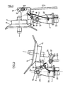
- the articulation (3) is in particular blocked by means of two stops (24, 25) arranged under the articulation (3) and by means of a locking device (17) in the form of a hook (18) capable of pivot about a central axis of rotation (18Y), cooperating with a stop (19) and being connected to a return spring (20).
- This blocking is important so that the raking wheels (5) of the side parts (1) remain stable during work. It prevents them from tilting around the joints (3) both when the machine is moved on the ground or when it is temporarily lifted, for example at the end of the ground.
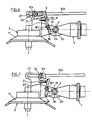
- the fixing element (10Y) of the operating device (10) is provided with a bent lug (21) arranged in such a way that when the telescopic part (10A) is in movement for move the lateral part (1) to the transport position, it abuts against the upper end of the hook (18) and thus drives it in rotation around the axis (18Y), causing it to be automatically unlocked (see Figures 6 and 7 ).
- the upper end of the hook (18) is connected to a cable (22) guided through an eyelet (23), so as to allow manual unlocking of the hook (18) (see figures 4 and 5).
- the angular movement of the raking wheel (5) in the working position is compensated by the oblong opening (27), the length of which is calculated so that it does not hamper an angular movement of about 10 ° towards the down and up.
- the raking wheel (5) can freely follow the unevenness of the ground without transmitting them to the operating device (10).
- the haymaking machine therefore works as if the joint (3) did not exist.
- the operating device (10) is actuated advantageously in the form of a hydraulic cylinder provided with two telescopic arms (10A) and (10B), after having unlocked the device. (17) by actuating the cable (22), for example, from the driver's seat, in the direction indicated by the arrow (F) (see Figure 4).
- this unlocking can also be done automatically thanks to the bent lug (21) arranged so that before it reaches the end of its travel in the oblong opening (27), it abuts against the upper end of the hook (18) in order to rotate it and thus cause unlocking (see Figures 6 and 7).
- the jack (10) initially causes the lifting of the raking wheel (5) which swings around the articulation (3). Then, the side part (1) folds around the pivot (4).
- the machine in the transport or storage position is shown in figure (3).
- the raking wheel (5) has thus tilted at an angle of approximately 180 ° relative to its working position and is found substantially upside down. In this position its forks are directed upwards and not outwards.
- this raking wheel (5) approaches the central part (9) of the chassis (2).
- this raking wheel (5) remains maintained in this position thanks to the jack (10).
- the operating device (10) is fixed to the portion of the lateral part (1) located not beyond the joint (3 ), but between the articulation (3) and the pivot (4) so as to cause the tilting wheel (5) to tilt and fold down under the effect of its own weight when the side part is moved in height by pivoting around the pivot (4).
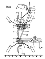
- the articulation (3) is unlocked manually by actuating the cable (22) in the direction indicated by the arrow (F) (see FIGS. 10 and 11).
- the side part (1) pivots around the pivot (4).
- the raking wheel (5) swings down around the joint (3), under the effect of its own weight, by an additional angle of approximately 90 ° up to that two stops (31 and 32) located above the joint (3) are in contact with each other.
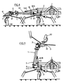
- the machine has six raking wheels, two of which (7) are fixed to the central part (9) of the chassis (2), and the other four in pairs (5 and 6) respectively on each of the two lateral parts (1) of the chassis (2), the assembly being perfectly symmetrical with respect to the longitudinal axis of the machine.
- each side part (1) is produced in two portions linked together by a pivot (12).
- the operating device (10) is located above the lateral part (1) and is fixed to the central part (9) and to the portion of said lateral part (1) situated beyond the pivot (12) lying between the articulation (3) and the axis of rotation (6Z) of the raking wheel (6), that is to say -display between the pivot (12) and the raking wheel (6) or on the raking wheel (6) itself, or even beyond this raking wheel (6), so as to directly cause the tilting and folding of raking wheels (5 and 6) when the lateral part (1) is moved in height by pivoting around the pivot (4).
- the pivots (4 and 12) allow the lateral part (1) to follow the unevenness of the ground transmitted by the wheels (30) of the machine.
- the central part (9) and the lateral part (1) of the chassis (2) comprise at (34) stops the position of which allows an angular movement downwards of approximately 10 °.
- These rods (38) are articulated at (40) in lugs (44) integral with the intermediate part (1) and in (39) in oblong holes (33) with lugs (43) integral with the outer part (1) of the chassis (2).
- the angular movement of said outer part of the chassis with the raking wheel (6) is defined by the oblong holes (33).
- the value of the angle of travel around the pivot (12) is approximately 20 ° (10 ° in each direction).
- the two joints (39, 40) are located substantially above the pivot (12) and the joint (3).
- Said articulation (3) is also locked in the working position thanks to the device (17) and completely blocked thanks to the two stops (24, 25) arranged under the articulation (3).
- the device (17) When it comes to putting the machine in the transport or storage position, the device (17) is manually unlocked using the cable (22), then the cylinder (10). The latter initially causes the lifting of the raking wheel (6) which swings around the pivot (12) until the rods (38) arrive at the end of their travel in the oblong orifices (33). Then, in a second step, the raking wheel (5) pivots around the articulation (3) until the two stops (35 and 36) located above the articulation (3) are in contact.
- the two rods (38) push the outer part (1) with the raking wheel (6) in a reverse rotation around the pivot (12), so that the raking wheel (6) pivots until the two stops (41 and 42) located below the pivot (12) are in contact.
- the intermediate part (1) then pivots around the pivot (4) by an angle of approximately 90 °.
- the machine in the transport or storage position is shown in Figure (13).
- the raking wheel (6) is found in a more or less vertical position, while the raking wheel (5) has rotated about 180 ° relative to its working position and is found upside down.
- the actuator (10) at the end of the race maintains the assembly in this position.
- the tilting of the other two raking wheels located on the other lateral part of the machine was carried out simultaneously and according to the same principle, so that the four raking wheels are in the folded position.
- the two outer raking wheels (6) of each side part (1) may touch each other. Therefore, it may be advantageous to provide the cover of the hub (11) of these raking wheels of a pad (8) of protection, also allowing better stabilization of the assembly.
- the forks of the raking wheels (5 and 6) are not dangerous, the height of the machine is reduced and the center of gravity lowered, due to the downward pivoting of the raking wheel (5) around the articulation (3).
- the operating device (10) is fixed to the portion of the lateral part (1) situated not beyond the pivot (12), but on the hub cover (11) of the wheel (5).
- said hub cover (11) of the wheel (5) has a lateral part (13) provided with a slot in which is guided a lug (26) of the operating device (10) .
- a bent piece (14) is connected to the lug (26) of the operating device (10).
- This part (14) has a slot (15) in which slides a lug (16) fixed on the part (1) carrying the raking wheel (6), near the pivot (12).
- the part (14) is moved and drives the lug (16) as soon as it is in contact with the lower end of the slot (15) in which it slides. Then, firstly, the raking wheel (5) swings up around the articulation (3) and the raking wheel (6) rotates around the pivot (12). The lug (16) then slides in the slot (15) of the part angled (14) until it stops at the upper end of said slot (15). The pivoting around the pivot (12) is then blocked, the raking wheel (6) having reached its folded position. The raking wheel (5) then continues to rock around the articulation (3) until the two stops (35 and 36) located above the articulation (3) come into contact. The side part (1) then pivots around the pivot (4) by an angle of approximately 90 ° and the machine reaches its transport or storage position as shown in Figure 15 of the accompanying drawings.
- the raking wheels (5 and 6) are in a position substantially identical to that indicated above (see Figure 13).
- the drive of the raking wheels (5 and 6) is offset by positioning the pinions, so that they do not touch in the folded position, their tools never coming into contact with each other, nor with the wheels. (30) of the machine.
- the machine can be provided with an automatic declutching device (28) of an electromagnetic transmission provided between the drive means going from the tractor to machine.
- This device provides instant disengagement of the drive when the side part (1) is lifted for tilting the raking wheels (5 and / or 6).
- the declutching device (28) could be, for example, in the form of a push button (29) disposed on the telescopic part (10B) of the control device (10), the telescopic part (10A) comprising a rod ( 37) which, when the control device (10) is actuated, slides on the telescopic part (10B) and comes into contact with the push button (29) which it actuates, thus causing an instantaneous disengagement.
- This declutching device (28) can be adapted to all types of machines described in the present invention. It has been shown, by way of nonlimiting example, in FIG. 16 of the appended drawings on the type of machine with six raking wheels represented in FIG. 14.
- the transmission will, of course, be provided with different articulations, preferably with cardan joints, arranged at the same height as the different pivots and articulations of the lateral parts (1).
Landscapes
- Life Sciences & Earth Sciences (AREA)
- Environmental Sciences (AREA)
- Agricultural Machines (AREA)
- Handcart (AREA)
- Vehicle Waterproofing, Decoration, And Sanitation Devices (AREA)
- Glass Compositions (AREA)
Claims (16)
Priority Applications (1)
| Application Number | Priority Date | Filing Date | Title |
|---|---|---|---|
| AT88440054T ATE69356T1 (de) | 1987-07-15 | 1988-06-30 | Heuwerbungsmaschine mit mehreren einschwenkbaren rechraedern zum zusammenlegen fuer den transport oder die unterbringung. |
Applications Claiming Priority (2)
| Application Number | Priority Date | Filing Date | Title |
|---|---|---|---|
| FR8710183 | 1987-07-15 | ||
| FR8710183A FR2618045B1 (fr) | 1987-07-15 | 1987-07-15 | Machine de fenaison munie de plusieurs roues rateleuses basculables en vue du repliement pour le transport ou le remisage |
Publications (2)
| Publication Number | Publication Date |
|---|---|
| EP0300937A1 EP0300937A1 (de) | 1989-01-25 |
| EP0300937B1 true EP0300937B1 (de) | 1991-11-13 |
Family
ID=9353289
Family Applications (1)
| Application Number | Title | Priority Date | Filing Date |
|---|---|---|---|
| EP88440054A Expired - Lifetime EP0300937B1 (de) | 1987-07-15 | 1988-06-30 | Heuwerbungsmaschine mit mehreren einschwenkbaren Rechrädern zum Zusammenlegen für den Transport oder die Unterbringung |
Country Status (4)
| Country | Link |
|---|---|
| EP (1) | EP0300937B1 (de) |
| AT (1) | ATE69356T1 (de) |
| DE (1) | DE3866180D1 (de) |
| FR (1) | FR2618045B1 (de) |
Families Citing this family (16)
| Publication number | Priority date | Publication date | Assignee | Title |
|---|---|---|---|---|
| FR2643783B1 (fr) * | 1989-03-01 | 1992-01-17 | Kuhn Sa | Machine de fenaison comportant plusieurs rotors |
| DE3938491A1 (de) * | 1989-07-08 | 1991-01-17 | Claas Saulgau Gmbh | Kreiselheumaschine |
| DE3926381C1 (en) * | 1989-08-10 | 1990-12-06 | Fella-Werke Gmbh, 8501 Feucht, De | Agricultural machine drive system - incorporates clutch with operating element connected to swivelling outer frame parts |
| DE4001709A1 (de) * | 1990-01-22 | 1991-07-25 | Fella Werke Gmbh | Landwirtschaftliche arbeitsmaschine |
| DE4005288C2 (de) * | 1990-02-20 | 1999-12-16 | Claas Saulgau Gmbh | Kreiselheumaschine mit verriegelbaren Außenarmen |
| FR2661312B1 (fr) * | 1990-04-27 | 1992-07-17 | Kuhn Sa | Machine de fenaison avec plusieurs rotors. |
| DE4114580C2 (de) * | 1991-05-04 | 1993-11-18 | Fella Werke Gmbh | Landwirtschaftliche Maschine mit veränderbarer Arbeitsbreite |
| FR2676327A1 (fr) * | 1991-05-14 | 1992-11-20 | Kuhn Sa | Andaineuse de vegetaux perfectionnee. |
| FR2680947B1 (fr) * | 1991-09-10 | 1993-11-19 | Kuhn Sa | Machine de fenaison comportant des roulettes orientables. |
| FR2696899B1 (fr) * | 1992-10-16 | 1994-12-09 | Kuhn Sa | Machine de fenaison pour l'andainage de fourrage. |
| FR2704385B1 (fr) * | 1993-04-28 | 1995-06-30 | Kuhn Sa | Machine agricole, notamment une andaineuse de fourrage. |
| FR2718324B1 (fr) * | 1994-04-12 | 1996-06-14 | Kuhn Sa | Machine de fenaison, notamment un andaineur, avec au moins un dispositif d'arrêt du rotor. |
| NL1002141C2 (nl) * | 1996-01-22 | 1997-07-25 | Maasland Nv | Landbouwmachine. |
| FR2754136B1 (fr) * | 1996-10-03 | 1999-01-22 | Kuhn Sa | Machine de fenaison comportant un chassis compose de plusieurs troncons articules entre eux |
| DE19823555A1 (de) * | 1998-05-27 | 1999-12-02 | Claas Saulgau Gmbh | Heuwerbungsmaschine |
| JP6251138B2 (ja) * | 2014-07-29 | 2017-12-20 | 株式会社タカキタ | 折り畳み可能なツインレーキ |
Citations (1)
| Publication number | Priority date | Publication date | Assignee | Title |
|---|---|---|---|---|
| EP0288416A1 (de) * | 1987-04-22 | 1988-10-26 | H. Niemeyer Söhne GmbH & Co. KG | Heuwerbungsmaschine |
Family Cites Families (12)
| Publication number | Priority date | Publication date | Assignee | Title |
|---|---|---|---|---|
| FR1346993A (fr) * | 1961-07-14 | 1963-12-27 | Fahr Ag Maschf | Dispositif facilitant le transport par route de machines de fenaison comportant plus de deux croisillons à dents |
| NL6404613A (de) * | 1964-04-27 | 1965-10-28 | ||
| US3643742A (en) * | 1969-01-02 | 1972-02-22 | Erwin W Wellendorf | Foldup implement |
| NL177070C (nl) * | 1979-08-24 | 1985-08-01 | Lely Nv C Van Der | Hooibouwmachine. |
| NL8401846A (nl) * | 1984-06-12 | 1986-01-02 | Multinorm Bv | Inrichting voor het bewerken van op de bodem liggend gewas. |
| FR2582186B1 (fr) * | 1985-05-21 | 1989-05-05 | Kuhn Sa | Perfectionnement aux machines de fenaison munies de plusieurs roues rateleuses |
| US4615397A (en) * | 1985-10-30 | 1986-10-07 | Deutz-Allis Corporation | Agricultural implement with double wing folding mechanism using toggle linkage and hydraulic actuator |
| DE3603014A1 (de) * | 1986-01-31 | 1987-08-06 | Kloeckner Humboldt Deutz Ag | Kreiselzettwender |
| DE8625784U1 (de) * | 1986-09-26 | 1987-03-05 | Kloeckner-Humboldt-Deutz Ag Zweigniederlassung Fahr, 7702 Gottmadingen, De | |
| DE8709233U1 (de) * | 1987-03-20 | 1987-12-10 | Khd Agrartechnik Gmbh, 7702 Gottmadingen, De | |
| DE8712441U1 (de) * | 1987-09-15 | 1987-10-29 | Fella-Werke Gmbh, 8501 Feucht, De | |
| DE8715674U1 (de) * | 1987-11-26 | 1988-01-28 | Fella-Werke Gmbh, 8501 Feucht, De |
-
1987
- 1987-07-15 FR FR8710183A patent/FR2618045B1/fr not_active Expired - Fee Related
-
1988
- 1988-06-30 DE DE8888440054T patent/DE3866180D1/de not_active Expired - Fee Related
- 1988-06-30 AT AT88440054T patent/ATE69356T1/de not_active IP Right Cessation
- 1988-06-30 EP EP88440054A patent/EP0300937B1/de not_active Expired - Lifetime
Patent Citations (1)
| Publication number | Priority date | Publication date | Assignee | Title |
|---|---|---|---|---|
| EP0288416A1 (de) * | 1987-04-22 | 1988-10-26 | H. Niemeyer Söhne GmbH & Co. KG | Heuwerbungsmaschine |
Also Published As
| Publication number | Publication date |
|---|---|
| ATE69356T1 (de) | 1991-11-15 |
| FR2618045B1 (fr) | 1990-06-08 |
| EP0300937A1 (de) | 1989-01-25 |
| DE3866180D1 (de) | 1991-12-19 |
| FR2618045A1 (fr) | 1989-01-20 |
Similar Documents
| Publication | Publication Date | Title |
|---|---|---|
| EP0300937B1 (de) | Heuwerbungsmaschine mit mehreren einschwenkbaren Rechrädern zum Zusammenlegen für den Transport oder die Unterbringung | |
| EP0203023B2 (de) | Heuerntemaschinen mit mehreren Rechenrädern | |
| EP0454602B1 (de) | Heuwerbungsmachine mit mehreren Kreiseln | |
| EP0356358B1 (de) | Mähmaschine mit verbessertem Rahmen | |
| EP0556143B1 (de) | Mähmaschine mit einer verbesserten Verriegelungsvorrichtung | |
| FR2463573A1 (fr) | Faneuse avec organes porteurs et arbres d'entrainement repliables | |
| EP0385899B1 (de) | Heuwerbungsmaschine mit mehreren Kreiseln | |
| EP1496734B1 (de) | Heuwerbungsmaschine | |
| EP0511922A1 (de) | Mähmaschine mit schwenkbarer Kupplungsstruktur | |
| WO2006079735A1 (fr) | Faucheuse avec un dispositif de depliage et de repliage perfectionne | |
| EP0310532B2 (de) | Heuwendemaschine mit einer verbesserten Schutzvorrichtung | |
| FR2664127A1 (fr) | Machine agricole, notamment une andaineuse de vegetaux, a largeur de travail reglable. | |
| EP0554200B1 (de) | Heuwerbungsmaschine mit einem mit gesteuerten Stützrädern versehenen Rahmen | |
| EP0797913B1 (de) | Heuwerbungsmaschine | |
| EP0426588B1 (de) | Verbesserung für landwirtschaftliche Maschinen insbesondere für Heuwerbungsmaschinen | |
| EP0558430B1 (de) | Heuschwader mit einem Mechanismus zur Unterbrechung des Rotorantriebes | |
| EP0593378B1 (de) | Heuwerbungsmaschine zum Schwaden von Halmgut | |
| EP1111986B1 (de) | Fahrwerk für landwirtschaftliche maschine | |
| FR2612362A1 (fr) | Machine centrifuge pour la fenaison | |
| EP0733302B1 (de) | Heuwerbungsmaschine | |
| FR2748188A1 (fr) | Machine de fenaison comportant un chassis avec des parties laterales repliables au moyen de verins hydrauliques | |
| FR2519835A1 (fr) | Dispositif d'attelage pour instrument agricole tracte | |
| FR2882621A1 (fr) | Andaineuse reversible | |
| FR2549687A1 (fr) | Faneuse avec organes porteurs et arbres d'entrainement repliables | |
| FR2687537A1 (fr) | Faneuse. |
Legal Events
| Date | Code | Title | Description |
|---|---|---|---|
| PUAI | Public reference made under article 153(3) epc to a published international application that has entered the european phase |
Free format text: ORIGINAL CODE: 0009012 |
|
| AK | Designated contracting states |
Kind code of ref document: A1 Designated state(s): AT DE FR IT NL |
|
| 17P | Request for examination filed |
Effective date: 19890613 |
|
| 17Q | First examination report despatched |
Effective date: 19900814 |
|
| GRAA | (expected) grant |
Free format text: ORIGINAL CODE: 0009210 |
|
| AK | Designated contracting states |
Kind code of ref document: B1 Designated state(s): AT DE FR IT NL |
|
| REF | Corresponds to: |
Ref document number: 69356 Country of ref document: AT Date of ref document: 19911115 Kind code of ref document: T |
|
| REF | Corresponds to: |
Ref document number: 3866180 Country of ref document: DE Date of ref document: 19911219 |
|
| ITF | It: translation for a ep patent filed |
Owner name: BARZANO' E ZANARDO MILANO S.P.A. |
|
| PLBI | Opposition filed |
Free format text: ORIGINAL CODE: 0009260 |
|
| 26 | Opposition filed |
Opponent name: C. VAN DER LELY N.V. Effective date: 19920812 |
|
| NLR1 | Nl: opposition has been filed with the epo |
Opponent name: C. VAN DER LELY N.V. |
|
| PLBM | Termination of opposition procedure: date of legal effect published |
Free format text: ORIGINAL CODE: 0009276 |
|
| STAA | Information on the status of an ep patent application or granted ep patent |
Free format text: STATUS: OPPOSITION PROCEDURE CLOSED |
|
| 27C | Opposition proceedings terminated |
Effective date: 19931031 |
|
| NLR2 | Nl: decision of opposition | ||
| PGFP | Annual fee paid to national office [announced via postgrant information from national office to epo] |
Ref country code: AT Payment date: 20040521 Year of fee payment: 17 |
|
| PGFP | Annual fee paid to national office [announced via postgrant information from national office to epo] |
Ref country code: DE Payment date: 20040526 Year of fee payment: 17 |
|
| PGFP | Annual fee paid to national office [announced via postgrant information from national office to epo] |
Ref country code: FR Payment date: 20040628 Year of fee payment: 17 |
|
| PGFP | Annual fee paid to national office [announced via postgrant information from national office to epo] |
Ref country code: NL Payment date: 20040630 Year of fee payment: 17 |
|
| PG25 | Lapsed in a contracting state [announced via postgrant information from national office to epo] |
Ref country code: IT Free format text: LAPSE BECAUSE OF NON-PAYMENT OF DUE FEES;WARNING: LAPSES OF ITALIAN PATENTS WITH EFFECTIVE DATE BEFORE 2007 MAY HAVE OCCURRED AT ANY TIME BEFORE 2007. THE CORRECT EFFECTIVE DATE MAY BE DIFFERENT FROM THE ONE RECORDED. Effective date: 20050630 Ref country code: AT Free format text: LAPSE BECAUSE OF NON-PAYMENT OF DUE FEES Effective date: 20050630 |
|
| PG25 | Lapsed in a contracting state [announced via postgrant information from national office to epo] |
Ref country code: NL Free format text: LAPSE BECAUSE OF NON-PAYMENT OF DUE FEES Effective date: 20060101 |
|
| PG25 | Lapsed in a contracting state [announced via postgrant information from national office to epo] |
Ref country code: DE Free format text: LAPSE BECAUSE OF NON-PAYMENT OF DUE FEES Effective date: 20060103 |
|
| PG25 | Lapsed in a contracting state [announced via postgrant information from national office to epo] |
Ref country code: FR Free format text: LAPSE BECAUSE OF NON-PAYMENT OF DUE FEES Effective date: 20060228 |
|
| NLV4 | Nl: lapsed or anulled due to non-payment of the annual fee |
Effective date: 20060101 |
|
| REG | Reference to a national code |
Ref country code: FR Ref legal event code: ST Effective date: 20060228 |