EP0297486A2 - Papierzuführvorrichtung für Drucker - Google Patents
Papierzuführvorrichtung für Drucker Download PDFInfo
- Publication number
- EP0297486A2 EP0297486A2 EP88110230A EP88110230A EP0297486A2 EP 0297486 A2 EP0297486 A2 EP 0297486A2 EP 88110230 A EP88110230 A EP 88110230A EP 88110230 A EP88110230 A EP 88110230A EP 0297486 A2 EP0297486 A2 EP 0297486A2
- Authority
- EP
- European Patent Office
- Prior art keywords
- paper
- platen
- feeding
- roller
- printing
- Prior art date
- Legal status (The legal status is an assumption and is not a legal conclusion. Google has not performed a legal analysis and makes no representation as to the accuracy of the status listed.)
- Granted
Links
Images


Classifications
-
- B—PERFORMING OPERATIONS; TRANSPORTING
- B41—PRINTING; LINING MACHINES; TYPEWRITERS; STAMPS
- B41J—TYPEWRITERS; SELECTIVE PRINTING MECHANISMS, i.e. MECHANISMS PRINTING OTHERWISE THAN FROM A FORME; CORRECTION OF TYPOGRAPHICAL ERRORS
- B41J11/00—Devices or arrangements of selective printing mechanisms, e.g. ink-jet printers or thermal printers, for supporting or handling copy material in sheet or web form
- B41J11/36—Blanking or long feeds; Feeding to a particular line, e.g. by rotation of platen or feed roller
-
- B—PERFORMING OPERATIONS; TRANSPORTING
- B41—PRINTING; LINING MACHINES; TYPEWRITERS; STAMPS
- B41J—TYPEWRITERS; SELECTIVE PRINTING MECHANISMS, i.e. MECHANISMS PRINTING OTHERWISE THAN FROM A FORME; CORRECTION OF TYPOGRAPHICAL ERRORS
- B41J11/00—Devices or arrangements of selective printing mechanisms, e.g. ink-jet printers or thermal printers, for supporting or handling copy material in sheet or web form
- B41J11/48—Apparatus for condensed record, tally strip, or like work using two or more papers, or sets of papers, e.g. devices for switching over from handling of copy material in sheet form to handling of copy material in continuous form and vice versa or point-of-sale printers comprising means for printing on continuous copy material, e.g. journal for tills, and on single sheets, e.g. cheques or receipts
-
- B—PERFORMING OPERATIONS; TRANSPORTING
- B41—PRINTING; LINING MACHINES; TYPEWRITERS; STAMPS
- B41J—TYPEWRITERS; SELECTIVE PRINTING MECHANISMS, i.e. MECHANISMS PRINTING OTHERWISE THAN FROM A FORME; CORRECTION OF TYPOGRAPHICAL ERRORS
- B41J13/00—Devices or arrangements of selective printing mechanisms, e.g. ink-jet printers or thermal printers, specially adapted for supporting or handling copy material in short lengths, e.g. sheets
- B41J13/02—Rollers
- B41J13/03—Rollers driven, e.g. feed rollers separate from platen
-
- B—PERFORMING OPERATIONS; TRANSPORTING
- B41—PRINTING; LINING MACHINES; TYPEWRITERS; STAMPS
- B41J—TYPEWRITERS; SELECTIVE PRINTING MECHANISMS, i.e. MECHANISMS PRINTING OTHERWISE THAN FROM A FORME; CORRECTION OF TYPOGRAPHICAL ERRORS
- B41J15/00—Devices or arrangements of selective printing mechanisms, e.g. ink-jet printers or thermal printers, specially adapted for supporting or handling copy material in continuous form, e.g. webs
- B41J15/16—Means for tensioning or winding the web
Definitions
- the present invention relates to a paper feeding apparatus for a printer.
- a roller having a diameter smaller than the platen provided at the upper portion of a printing head and located at the feeding-out side with respect to the printing head is pressed against the platen with said paper therebetween to generate frictional force, whereby the fed-out portion of paper after printing is drawn.
- the paper feeding speed of the supplying side and that of the feeding-out side are both determined by the platen so that no difference is caused between both speeds.
- the main power is not provided by a platen but by a sprocket or a belt having pins to be inserted into the feeding holes. Therefore, a fine difference of speed between the platen and the sprocket is caused due to changes of the ambient temperature, and paper sagging, tearing of feeding holes and other troubles are caused by repeating paper feeding for a long distance.
- High positional accuracy of the paper with respect to a printing head and stable pa per feeding over a long period of time cannot be achieved in the above method.
- a paper bail pressing paper against the cylindrical platen is switched by a solenoid between a position in which the bail is in touch with the platen and a position in which the bail is released from the platen, and the paper bail, in the condition that the kinetic energy thereof is not absorbed, comes in touch with the paper on the platen or in touch with a stopper at the release position causing mechanical shocks.
- the impact noice caused by abrasion or impingement at a junction portion of a paper bail shaft with a paper bail lever or at a junction portion of a paper bail lever with a loading lever is rasping, and further, a trace of the paper bail is left on pressure sensitive paper due to the impact when the paper bail is returned to the pressing position after releasing. Furthermore, if a mechanical dumper is attached in order to lighten the impact, the device becomes complicated and large-sized.
- a positioning operation to set the printing start position after setting paper onto a platen is described herein below.
- Fig. 15 is a cross sectional view for explaining a conventional controlling method.
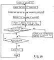
- Fig. 14 shows a flow chart of a loading sequence in a printer having a conventional autoloading function.
- the end of paper 13 is stopped at the position where paper-feeding roller 58 is pressed against platen 55 and is adjusted to position S.
- platen 55 rotates in the direction of arrow U by a predetermined amount to feed the paper out in the direction of arrow P.
- the loading sequence is completed when the paper end from position S is fed to a predetermined start position R. Then the apparatus is in the condition of waiting for printing data.
- a roller made of rubber or similar material is provided at the upper portion of the platen, which corresponds to the slip stream side in the paper-feeding direction with respect to the printing head, and the roller is rotated at the same or a higher peripheral speed as the peripheral speed of the platen, whereby printed paper is fed out to contact the periphery of the roller and is drawn by frictional force thereof. Therefore, paper is fed accurately and steadily in any ambient condition or with any kind of paper, without tear of paper, jamming, inferiority of the paper feeding accuracy caused by a deflection of paper.
- a driving means is energized before the paper pressure lever returns to the paper pressing position by the returning force of a pressure member just after the holding power of the driving means is released at the moment of the returning movement of the paper pressure lever.
- the impact in each portion can be reduced similar to the closing movement by a plurality of energizations of a loading solenoid, and the same effect thus can be obtained.
- the length from the leading edge of the paper to the initial printing position can be controlled precisely by the user with a button operation to rotate the motor for driving the platen forward or backward by minute steps. Therefore, dispersion of such length due to an inaccuracy of parts can be corrected and the paper can be loaded precisely to an initial printing position more correctly and easily than by a manual adjustment by turning the platen knob.
- the amount of motor rotation required for fine adjustment is stored in memory, in the next autoloading the paper is loaded by an amount of motor rotation including the initial amount set in the ROM and the amount of fine adjustment stored in the memory, which results in the autoloading of paper precisely to a desired position. Therefore, in the case of repeated printing on a specific position of cut sheets, the user does not have to repeat the paper positioning operation for each cut sheet and dispersion of printing position thus can be prevented.
- the embodiments described below are used in a serial type impact dot printer as an example.
- the embodiment of Fig. 1 is a printer wherein paper is guided to the feeding-out roller in use of a paper bail provided with a movable shaft.
- a paper bail provided with a movable shaft.
- a fixed paper-path for guiding the paper is provided in the embodiment of Fig. 2 .
- the embodiment of Fig. 3 has a paper bail such as in Fig. 1 and a roller to press the feeding-out roller with the paper therebetween.
- Fig. 1(a) is a plan view and Fig. 1(b) is a sectional view of a first embodiment.
- platen 5 For wrapping printing paper 13 around platen 5 made of rubber or a similar material, and positioning and feeding it toward printing head 7, platen 5 is arranged such that a space is defined between platen 5 and printing head 7 during reciprocating movement of the latter in the direction of arrow a.
- d At an upstream position of printing head 7 with respect to the paper feeding direction d (Fig.
- paper feeding rollers 8 and 9 are arranged below the platen, and a paper guide plate 10 for guiding the leading edge of paper 13 toward the front of printing head 7 is arranged so as to partly wrap around the peripheral surface of platen 5 with a space therebetween from the vicinity of a tractor 11 (described later) to the vicinity of the lower portion of printing head 7. Further, at the upstream side of paper guide plate 10, tractor 11 utilizing a belt with pins having the same diameter and pitch as those of feeding holes of fanfold paper is arranged.
- a rod movable in the direction of arrow e as a paper bail 12 for guiding the leading edge of printing paper 13 toward the gap between a paper feeding-out roller 1 and an auxiliary paper feeding-out roller 2 is disposed above printing head 7.
- paper bail 12 at the downstream side in the paper feeding direction, paper feeding-out rollers 1 having the same friction coefficient as rubber or the like and being driven in the direction of arrow c to draw printing paper 13, and auxiliary paper feeding-out rollers 2 are disposed.
- auxiliary rollers 2 overlaps by h with that of feeding-out rollers 1, and there is a space in between each side of a feeding-out roller 1 and the adjacent auxiliary roller 2.
- Feeding-out rollers are fixed to feeding-out roller shaft 3 by press fitting or the like for preventing idle running, so that it rotates with the feeding-out roller shaft.
- Auxiliary feeding-out rollers 2 are rotatably supported on auxiliary feeding-out roller shaft 4, so that friction load with respect to the movement of paper is not caused at the contact portion of feeding-out roller 2 with the printing paper and paper feeding-out rollers 2 can perform idle running.
- Auxiliary feeding-out roller shaft 4 is fixed at frame 19 in order not to allow an idle running.
- Feeding-out roller shaft 3 and platen 5 pass through and engage with frame 19 and are positioned so as to be smoothly rotatable.
- the portion of shaft 3 and that of the shaft of the platen 5, projecting from frame 19 are fixed to gears 16 and 18, respectively so as not to cause idle running.
- Paper feeding motor 6, platen 5 and paper feeding-out roller shaft 3 are mechanically coupled by a gear train consisting of gears 14 to 18.
- tractor 11 is not utilized and printing paper is directly inserted between paper guide plate 10 and platen 5.
- a cut sheet is pressed against platen 5 with high load by paper feeding rollers 8 and 9 (shown by imaginary lines in Fig. 1(b)) and the cut sheet is positioned and moved in accordance with the rotation of platen 5 by frictional force. Accordingly, since printing paper is fed by the peripheral surface of platen 5 which is the area where printing is actually effected, the positional accuracy with respect to printing is high.
- paper feeding rollers 8 and 9 are separated from platen 5 as shown in Fig. 1(b), and printing paper 13 is hooked by pins of tractor 11 and is inserted into an opening between paper guide plate 1 and the periphery of platen 5.
- both cut sheet and fanfold paper are fed toward paper bail 12, wrapping around the periphery of platen 5 through the front of printing head 7.
- Paper bail 12 is located at the position apart from platen 5 shown by a broken line in Fig.
- paper bail 12 moves to the position indicated by a solid line in the direction of arrow e and guides the leading edge so that it is drawn automatically into the opening between feeding-out roller 1 and auxiliary feeding-out roller 2.
- the power for the series of paper feeding operations is obtained by the rotational force of paper feed motor 6.
- Pinion gear 14 fixed to the tip portion of the motor axis is rotated by the rotation of motor 6, and the rotational power is transmitted to platen gear 16 which is fixed to the shaft of platen 5 to rotate platen 5 through reduction gear 15. Further, platen gear 16 rotates several feeding-out rollers 1 fixed to feeding-out roller shaft 3 in the column direction by rotating feeding-out roller gear 18 fixed to shaft 3 through transmission gear 17.
- the peripheral speed Vb of platen 5 is the same as or higher than the peripheral speed Vc of feeding-out rollers 1 by several percents (Vc > Vb).
- tractor 11 is so arranged that the peripheral speed Va of the tractor and the peripheral speed Vb of the platen have the relation Vb ⁇ Va.
- feeding-out rollers 1 and auxiliary feeding-out rollers 2 are so arranged that they overlap each other by an amount h (as shown in the cross sectional view of Fig. 1(b)) and are arranged with a gap i therebetween (as shown in the plan view of Fig. 1(a)). Therefore, the paper inserted between these rollers is sagged and is pressed against each roller by the restoring force of the paper, and the paper is fed out in accordance with the rotation of these rollers by the frictional force generated between the paper and the rollers.
- the restoring force of the paper due to the sagging differs depending on the kind of paper, so that thicker paper has a stronger restoring force. Accordingly, for thick paper being apt to generate sagging by its weight on the way from tractor 11 to feeding-out rollers 1, such sagging is prevented by strong feeding-out force. On the contrary, for thin paper having small restoring force and being easily broken when strong stress is concentrated on the pins of tractor 11 with too large a tensile force, the tensile force is reduced to prevent tearing of the feeding holes. In such a man ner, the feeding-out force is self-controlled automatically in accordance with the thickness of the paper.
- the feeding force generated by platen 5 located at an intermediate position in the paper feeding mechanism is not utilized since paper bail 12 is not pressed directly against platen 5 with the paper therebetween but is used only for guiding the paper being apart from platen 5, so that it depends on the contact angle of paper with respect to platen 5 and the feeding-out force generated by feeding-out roller 1. Therefore, the feeding force has the same relation as that of the feeding-out force and is self-controlled in accordance with the thickness of paper.
- a guide cover 20 which is integrally formed from transparent resin is utilized in place of a paper bail and auxiliary feeding-out rollers.
- a rib portion 20a is integrally formed with a plate portion 20b extending in the column direction. Paper is guided by the ridgeline portion of rib portion 20a.
- Both ends of paper guide cover 20 are fixed to frame 19 by screws 21.
- a sprocket wheel 22 and sprocket cover 23 for preventing the paper from rising up are arranged in place of a tractor utilizing a belt when fanfold paper with holes for feeding is utilized.
- Fig. 3 showing a third embodiment wherein auxiliary feeding-out rollers 2a are arranged so as to be directly pressed against feeding-out rollers 1, instead of being arranged at both ends of feeding-out rollers 1.
- the pressing load is produced by a tension spring 31 attached between the end portion of auxiliary feeding-out roller shaft 4 and a spring peg 25 projecting through feeding-out roller frame 30.
- Feeding-out roller shaft 3, feeding-out roller gear 18 and transmission gear 17 are fixed to a feeding-out roller frame 30 and form a removable unit which is separate from frame 19.
- Paper bail 12 is fixed to a paper bail lever 24 pivoting on a shaft 28 projecting through frame 19 and is rotatable in the direction of arrow e.
- Printing paper 13 is pressed by a pressure force produced by a tension spring 32 connecting shaft 29 projecting through frame 19, and shaft 27 projecting through paper bail lever 24. Further, when the above unit is mounted, paper bail lever 24 is adjusted by stopper pin 26 projecting through feeding-out roller frame 30, whereby paper bail 12 is kept away from platen 5 as shown in Fig. 3. On the other hand, when the unit is not mounted, paper bail 12 is utilized as in a conventional printer, i.e. paper bail 12 is pressed against the periphery of platen 5 by tension spring 31, and another unit such as a cut sheet feeder can be mounted. The other arrangement is the same as with the first embodiment shown in Fig. 1.
- an auxiliary feeding-out roller in place of contacting printing paper with feeding-out roller 1 by the restoring force produced by paper sagging due to an overlapping of feeding-out roller 1 with auxiliary feeding-out roller 2a, an auxiliary feeding-out roller is pressed by tension spring 31 against feeding-out roller 1 with printing paper 13 therebetween, so that the feeding-out force for printing paper 13 is determined by the load of tension spring 31 and the surface friction coefficient of feeding-out roller 1.
- Fig. 4 is a block diagram showing an embodiment.
- Voltage detector circuit 130 is coupled to the input of analog-to-digital conversion circuit 131 (hereinafter referred to as A/D conversion circuit).
- the output line of A/D conversion circuit 131 is coupled to the input port of input/output interface 132 (hereinafter referred to as IOP), and the output of IOP 132 is coupled to the bases of transistors Q1 and Q2 of a solenoid driving circuit shown in Fig. 5.
- IOP 132 is coupled to microprocessor 133 (hereinafter referred to as CPU) and to ROM/RAM 134.
- a change in voltage from the value of 35V is detected by voltage detector circuit 130 and is converted into a digital signal by A/D conversion circuit 131. Then the digital signal is inputted into IOP 132.
- CPU 133 detects the condition of IOP 132, changes attraction time width of loading solenoid 46 in accordance with the output of CPU 133 corresponding to that condition, and turns on transistor Q1.
- the driving time of transistors Q1 and Q2 is set in accordance with the combination of the level of the output line of A/D conversion circuit 131, and a counted value corresponding to the time is stored in ROM/RAM 134 and is read out by CPU 33, whereby transistors Q1 and Q2 are properly controlled.
- Fig. 5 is a driving circuit for exciting the solenoid.
- the collector of transistor Q1 and that of transistor Q2 are connected to loading solenoid 46 and a nominal voltage of 35V is applied to loading solenoid 46 by turning on transistors Q1 and Q2. Further, a nominal voltage of 5V is applied to loading solenoid 46 by turning-off transistor Q1 and turning-on transistor Q2.
- loading solenoid 46 is energized by tuning on transistors Q1 and Q2 of Fig. 5 simultaneously and paper bail lever 12L is opened through loading lever 47.
- release position B i.e. after a period of time t1 (Fig. 6)
- transistor Q1 is turned off, and after a further period of time t2, transistor Q1 is turned on again.
- an unstable movement of paper bail lever 12L due to a change in the driving voltage can be corrected by properly setting the energizing period t1, in accordance with the change in driving voltage, and, thus, the impact when paper bail lever 12L reaches release position B can be reduced.
- transistor Q1 of Fig. 5 is turned off while paper bail lever 12L is kept at the release position B. Due to the above controlling, the attraction force of loading solenoid 46 is released halfway, and the energy is absorbed by the tensile force of paper bail pressure lever spring 48 in the opposite direction to the inertia force around fulcrum 12a. Thus, the speed of the movement of paper bail 12 reaching release position B can be reduced.
- loading solenoid is energized only one time in this embodiment, however, the same effect can be achieved by two or more times of ON-OFF controlling.
- t1 is varied in accordance with the variation of the driving voltage in this embodiment. However, if t2 is varied so as to, for instance, shorten the period when the driving voltage is low and prolong the period when the driving voltage is high, the same effect can be obtained.
- FIG. 12 is a schematic cross sectional view of an apparatus according to the present invention using a cut sheet and Fig. 11 is an example of a flow chart of the loading sequence thereof.
- paper feeding motor 6 (Fig. 1) is driven by a rotational amount stored in a ROM and an amount stored in a memory (RAM) and the driving force of the paper feeding motor is transmitted to platen 5 through the transmission means to rotate platen 5 in the direction of arrow U. Thereby the end of paper 13 is fed from position E to position G to complete paper positioning for the start of printing. After that, the apparatus is in the condition of waiting for printing data.
- the paper feeding motor is rotated forward or backward by minute steps.
- a switch for fine adjustment provided on the operation panel or the like is used while the apparatus is in the condition of waiting for printing data, in order to rotate platen 5 through a gear train in the direction of arrow U or in the direction opposite thereto. Since the paper located at position G is fed by a very small amount in the direction of arrow P or in the direction opposite thereto, a user can position the paper at the desired position (for instance, at position F) easily and correctly without manual operation to rotate the platen knob. This fine adjustment operation can be continued until the input of the next printing data.
- the rotational amount required for the fine adjustment is added to or subtracted from a value in the memory and is stored therein (as mentioned above the initial value is 0).
- the paper feeding motor is driven by a rotational amount stored in the ROM (feeding the paper to position G) and a further amount stored in the memory (length A) so that the paper is immediately fed to position F. Therefore, it is unnecessary to position each paper individually for the printing start, which improves remarkably the facility of the apparatus. Further, if many papers are printed, each paper is set at the correct position without variation of the printing position.
- the memory is cleared when the power of the printer is turned off. However, if the memory is backed up, the starting position of the last printing is stored and maintained in the memory by the time that the user repositions the printing start position after once turning-off the power source. Thus, it is very convenient for printing on many sheets of papers in a specific format.
- Fig. 13 is a cross sectional view of an other embodiment of the present invention utilizing a fanfold paper.
- Tractor 11 on which fanfold paper is set and platen 5 are driven by a motor through a gear train.
- tractor 11 and platen 5 are driven in the direction of arrow j and k, respectively, and printing paper 13 is fed in the direction of arrow m.
- the end of paper 13 gradually presses a paper detecting sensor 44 downward from position 45a , and sensor 44 detects the paper at position 45b.
- the end of printing paper 13 is at a position 13t, which corresponds to position E in Fig. 12, and serves as the reference position for leading the paper to a desired start position.
- the motor After a detection of paper 13 by paper detector sensor 44, the motor is driven by a rotational amount stored in the ROM and an amount stored in the memory for the start of printing.
- the fine adjustment operation is carried out in the same manner as in the above embodiments.
- the printing start position is unstable.
- the user can re-position the printing start position by fine adjustment so that printing can always be started from a desired position, not influenced by such variations.
Applications Claiming Priority (8)
| Application Number | Priority Date | Filing Date | Title |
|---|---|---|---|
| JP163495/87 | 1987-06-30 | ||
| JP62163495A JPH0811461B2 (ja) | 1987-06-30 | 1987-06-30 | プリンタの紙送り機構 |
| JP163496/87 | 1987-06-30 | ||
| JP16349687A JPS648066A (en) | 1987-06-30 | 1987-06-30 | Printing paper cuing position controller for printer |
| JP176404/87 | 1987-07-15 | ||
| JP176405/87 | 1987-07-15 | ||
| JP17640487A JP2681932B2 (ja) | 1987-07-15 | 1987-07-15 | プリンタの紙押え装置 |
| JP62176405A JP2689430B2 (ja) | 1987-07-15 | 1987-07-15 | プリンタの紙押え装置 |
Publications (3)
| Publication Number | Publication Date |
|---|---|
| EP0297486A2 true EP0297486A2 (de) | 1989-01-04 |
| EP0297486A3 EP0297486A3 (en) | 1990-02-28 |
| EP0297486B1 EP0297486B1 (de) | 1993-09-08 |
Family
ID=27473869
Family Applications (1)
| Application Number | Title | Priority Date | Filing Date |
|---|---|---|---|
| EP19880110230 Expired - Lifetime EP0297486B1 (de) | 1987-06-30 | 1988-06-27 | Papierzuführvorrichtung für Drucker |
Country Status (3)
| Country | Link |
|---|---|
| EP (1) | EP0297486B1 (de) |
| DE (1) | DE3883872T2 (de) |
| HK (1) | HK72295A (de) |
Cited By (12)
| Publication number | Priority date | Publication date | Assignee | Title |
|---|---|---|---|---|
| GB2227460A (en) * | 1989-01-11 | 1990-08-01 | Monarch Marking Systems Inc | Label printing apparatus. |
| EP0385615A1 (de) * | 1989-02-16 | 1990-09-05 | Mitsubishi Denki Kabushiki Kaisha | Wärmedrucker |
| FR2647055A1 (fr) * | 1989-01-11 | 1990-11-23 | Monarch Marking Systems Inc | Appareil d'impression d'etiquettes |
| DE3939506A1 (de) * | 1989-05-22 | 1990-11-29 | Mannesmann Ag | Einrichtung fuer den papiertransport in druckern, insbesondere in matrixdruckern |
| GB2232640A (en) * | 1989-04-24 | 1990-12-19 | Brother Ind Ltd | Initialising position of continuous stationery in selective printers |
| WO1991007284A1 (en) * | 1989-11-13 | 1991-05-30 | Eastman Kodak Company | Improved compact printer having sheet and tractor media selections |
| EP0430381A2 (de) * | 1989-11-27 | 1991-06-05 | MANNESMANN Aktiengesellschaft | Einrichtung für den Transport mehrlagiger, randgelochter Aufzeichnungsträger |
| EP0457584A1 (de) * | 1990-05-17 | 1991-11-21 | Seiko Epson Corporation | Auf Band druckendes Gerät |
| EP0517401A2 (de) * | 1991-05-27 | 1992-12-09 | Seiko Epson Corporation | Druckmaschine |
| US5346322A (en) * | 1989-04-24 | 1994-09-13 | Brother Kogyo Kabushiki Kaisha | Printing device having paper feed control |
| EP0798123A2 (de) * | 1996-03-29 | 1997-10-01 | Canon Kabushiki Kaisha | Mechanismus zum Führen von Endlos- und Einzelpapier für ein Bildaufzeichnungsgerät |
| EP0958929A1 (de) * | 1998-05-20 | 1999-11-24 | Sagem Sa | Drucker eines Datenverabeitungsendgerätes |
Citations (4)
| Publication number | Priority date | Publication date | Assignee | Title |
|---|---|---|---|---|
| US4360279A (en) * | 1980-07-02 | 1982-11-23 | Brother Kogyo Kabushiki Kaisha | Printing paper feeding mechanism |
| EP0150980A2 (de) * | 1984-01-25 | 1985-08-07 | Tokyo Electric Co. Ltd. | Anordnung zur Papierzufuhr für einen Drucker |
| EP0195761A1 (de) * | 1985-03-20 | 1986-09-24 | Telefonaktiebolaget L M Ericsson | Papiertransport in Druckeinrichtungen |
| EP0202129A1 (de) * | 1985-05-15 | 1986-11-20 | Oki Electric Industry Company, Limited | Apparat zum Zuführen eines Druckmediums |
-
1988
- 1988-06-27 EP EP19880110230 patent/EP0297486B1/de not_active Expired - Lifetime
- 1988-06-27 DE DE19883883872 patent/DE3883872T2/de not_active Expired - Fee Related
-
1995
- 1995-05-11 HK HK72295A patent/HK72295A/xx not_active IP Right Cessation
Patent Citations (4)
| Publication number | Priority date | Publication date | Assignee | Title |
|---|---|---|---|---|
| US4360279A (en) * | 1980-07-02 | 1982-11-23 | Brother Kogyo Kabushiki Kaisha | Printing paper feeding mechanism |
| EP0150980A2 (de) * | 1984-01-25 | 1985-08-07 | Tokyo Electric Co. Ltd. | Anordnung zur Papierzufuhr für einen Drucker |
| EP0195761A1 (de) * | 1985-03-20 | 1986-09-24 | Telefonaktiebolaget L M Ericsson | Papiertransport in Druckeinrichtungen |
| EP0202129A1 (de) * | 1985-05-15 | 1986-11-20 | Oki Electric Industry Company, Limited | Apparat zum Zuführen eines Druckmediums |
Cited By (19)
| Publication number | Priority date | Publication date | Assignee | Title |
|---|---|---|---|---|
| GB2227460A (en) * | 1989-01-11 | 1990-08-01 | Monarch Marking Systems Inc | Label printing apparatus. |
| FR2647055A1 (fr) * | 1989-01-11 | 1990-11-23 | Monarch Marking Systems Inc | Appareil d'impression d'etiquettes |
| GB2227460B (en) * | 1989-01-11 | 1993-10-06 | Monarch Marking Systems Inc | Printing apparatus |
| EP0385615A1 (de) * | 1989-02-16 | 1990-09-05 | Mitsubishi Denki Kabushiki Kaisha | Wärmedrucker |
| GB2232640A (en) * | 1989-04-24 | 1990-12-19 | Brother Ind Ltd | Initialising position of continuous stationery in selective printers |
| US5346322A (en) * | 1989-04-24 | 1994-09-13 | Brother Kogyo Kabushiki Kaisha | Printing device having paper feed control |
| GB2232640B (en) * | 1989-04-24 | 1993-06-30 | Brother Ind Ltd | Printing device with means for setting print start position on continuous stationery |
| DE3939506A1 (de) * | 1989-05-22 | 1990-11-29 | Mannesmann Ag | Einrichtung fuer den papiertransport in druckern, insbesondere in matrixdruckern |
| WO1991007284A1 (en) * | 1989-11-13 | 1991-05-30 | Eastman Kodak Company | Improved compact printer having sheet and tractor media selections |
| EP0430381A2 (de) * | 1989-11-27 | 1991-06-05 | MANNESMANN Aktiengesellschaft | Einrichtung für den Transport mehrlagiger, randgelochter Aufzeichnungsträger |
| EP0430381A3 (en) * | 1989-11-27 | 1991-09-25 | Mannesmann Aktiengesellschaft | Device for transporting multilayer and margin-perforated recording supports |
| EP0457584A1 (de) * | 1990-05-17 | 1991-11-21 | Seiko Epson Corporation | Auf Band druckendes Gerät |
| EP0517401A3 (en) * | 1991-05-27 | 1993-08-04 | Seiko Epson Corporation | Printing machine |
| EP0517401A2 (de) * | 1991-05-27 | 1992-12-09 | Seiko Epson Corporation | Druckmaschine |
| EP0798123A2 (de) * | 1996-03-29 | 1997-10-01 | Canon Kabushiki Kaisha | Mechanismus zum Führen von Endlos- und Einzelpapier für ein Bildaufzeichnungsgerät |
| EP0798123A3 (de) * | 1996-03-29 | 1997-11-05 | Canon Kabushiki Kaisha | Mechanismus zum Führen von Endlos- und Einzelpapier für ein Bildaufzeichnungsgerät |
| US5899613A (en) * | 1996-03-29 | 1999-05-04 | Canon Kabushiki Kaisha | Image recording apparatus having conveying means for both continuous sheet and single sheet |
| EP0958929A1 (de) * | 1998-05-20 | 1999-11-24 | Sagem Sa | Drucker eines Datenverabeitungsendgerätes |
| FR2778870A1 (fr) * | 1998-05-20 | 1999-11-26 | Sagem | Imprimante de terminal de traitement de donnees |
Also Published As
| Publication number | Publication date |
|---|---|
| HK72295A (en) | 1995-05-19 |
| EP0297486B1 (de) | 1993-09-08 |
| DE3883872D1 (de) | 1993-10-14 |
| DE3883872T2 (de) | 1994-02-10 |
| EP0297486A3 (en) | 1990-02-28 |
Similar Documents
| Publication | Publication Date | Title |
|---|---|---|
| EP0609560B1 (de) | Bogenförderapparat | |
| US9387708B2 (en) | Roll paper transportation device and printing apparatus | |
| US5620174A (en) | Sheet conveying apparatus | |
| EP0297486A2 (de) | Papierzuführvorrichtung für Drucker | |
| US6343884B1 (en) | Paper roll loading method and printer using the method | |
| US5818487A (en) | Ink jet printer | |
| CA1139986A (en) | In-feed paper buckel control apparatus | |
| US5199806A (en) | Apparatus for feeding individual sheets of paper as well as continuous fan fold paper utilizing a platen | |
| US5221150A (en) | Paper feeding apparatus for printers having a bail roller means | |
| EP0313404B1 (de) | Anordnung zur selbsttätigen Papierzufuhr in einem Drucker, versehen mit einem Bügelbetätigungsmechanismus | |
| US4775254A (en) | Lining method and apparatus for printers | |
| US5417415A (en) | Method of straightening skew in cut sheet and apparatus therefor | |
| US5810492A (en) | Printer and print start method therefore | |
| JPH10139235A (ja) | 記録装置の排出機構 | |
| JP3012073B2 (ja) | 記録装置 | |
| JPS63137869A (ja) | 印字ヘツドの自動紙厚調整装置 | |
| JP4274392B2 (ja) | ロールシート供給装置及び画像形成装置 | |
| JP3197088B2 (ja) | シート搬送装置 | |
| JP2503857B2 (ja) | インクジェット記録装置 | |
| JPH10297790A (ja) | プリンタの用紙搬送方法および用紙搬送装置 | |
| JPH06143717A (ja) | インクジェットプリンタ | |
| JP3802573B2 (ja) | プリンタ | |
| JPS59104981A (ja) | インクジエツトプリンタ | |
| JPH06336064A (ja) | プリンタの用紙搬送機構および用紙搬送制御方法 | |
| JPH04118269A (ja) | 転写記録装置 |
Legal Events
| Date | Code | Title | Description |
|---|---|---|---|
| PUAI | Public reference made under article 153(3) epc to a published international application that has entered the european phase |
Free format text: ORIGINAL CODE: 0009012 |
|
| AK | Designated contracting states |
Kind code of ref document: A2 Designated state(s): DE ES FR GB IT |
|
| PUAL | Search report despatched |
Free format text: ORIGINAL CODE: 0009013 |
|
| AK | Designated contracting states |
Kind code of ref document: A3 Designated state(s): DE ES FR GB IT |
|
| 17P | Request for examination filed |
Effective date: 19900523 |
|
| 17Q | First examination report despatched |
Effective date: 19920227 |
|
| RBV | Designated contracting states (corrected) |
Designated state(s): DE FR GB IT |
|
| GRAA | (expected) grant |
Free format text: ORIGINAL CODE: 0009210 |
|
| AK | Designated contracting states |
Kind code of ref document: B1 Designated state(s): DE FR GB IT |
|
| ITF | It: translation for a ep patent filed |
Owner name: JACOBACCI CASETTA & PERANI S.P.A. |
|
| REF | Corresponds to: |
Ref document number: 3883872 Country of ref document: DE Date of ref document: 19931014 |
|
| ET | Fr: translation filed | ||
| PLBE | No opposition filed within time limit |
Free format text: ORIGINAL CODE: 0009261 |
|
| STAA | Information on the status of an ep patent application or granted ep patent |
Free format text: STATUS: NO OPPOSITION FILED WITHIN TIME LIMIT |
|
| 26N | No opposition filed | ||
| REG | Reference to a national code |
Ref country code: GB Ref legal event code: IF02 |
|
| PGFP | Annual fee paid to national office [announced via postgrant information from national office to epo] |
Ref country code: FR Payment date: 20060608 Year of fee payment: 19 |
|
| PGFP | Annual fee paid to national office [announced via postgrant information from national office to epo] |
Ref country code: GB Payment date: 20060621 Year of fee payment: 19 |
|
| PGFP | Annual fee paid to national office [announced via postgrant information from national office to epo] |
Ref country code: DE Payment date: 20060622 Year of fee payment: 19 |
|
| PGFP | Annual fee paid to national office [announced via postgrant information from national office to epo] |
Ref country code: IT Payment date: 20070625 Year of fee payment: 20 |
|
| GBPC | Gb: european patent ceased through non-payment of renewal fee |
Effective date: 20070627 |
|
| REG | Reference to a national code |
Ref country code: FR Ref legal event code: ST Effective date: 20080229 |
|
| PG25 | Lapsed in a contracting state [announced via postgrant information from national office to epo] |
Ref country code: DE Free format text: LAPSE BECAUSE OF NON-PAYMENT OF DUE FEES Effective date: 20080101 |
|
| PG25 | Lapsed in a contracting state [announced via postgrant information from national office to epo] |
Ref country code: GB Free format text: LAPSE BECAUSE OF NON-PAYMENT OF DUE FEES Effective date: 20070627 |
|
| PG25 | Lapsed in a contracting state [announced via postgrant information from national office to epo] |
Ref country code: FR Free format text: LAPSE BECAUSE OF NON-PAYMENT OF DUE FEES Effective date: 20070702 |