EP0297307B1 - Einrichtung zur Durchführung von Kabeln - Google Patents
Einrichtung zur Durchführung von Kabeln Download PDFInfo
- Publication number
- EP0297307B1 EP0297307B1 EP88108882A EP88108882A EP0297307B1 EP 0297307 B1 EP0297307 B1 EP 0297307B1 EP 88108882 A EP88108882 A EP 88108882A EP 88108882 A EP88108882 A EP 88108882A EP 0297307 B1 EP0297307 B1 EP 0297307B1
- Authority
- EP
- European Patent Office
- Prior art keywords
- frame
- housing
- rear wall
- wall
- filling pieces
- Prior art date
- Legal status (The legal status is an assumption and is not a legal conclusion. Google has not performed a legal analysis and makes no representation as to the accuracy of the status listed.)
- Expired - Lifetime
Links
- 239000000945 filler Substances 0.000 description 29
- 230000008878 coupling Effects 0.000 description 5
- 238000010168 coupling process Methods 0.000 description 5
- 238000005859 coupling reaction Methods 0.000 description 5
- 238000004026 adhesive bonding Methods 0.000 description 1
- 238000006243 chemical reaction Methods 0.000 description 1
- 150000001875 compounds Chemical class 0.000 description 1
- 239000000428 dust Substances 0.000 description 1
- 238000004382 potting Methods 0.000 description 1
Images
Classifications
-
- H—ELECTRICITY
- H02—GENERATION; CONVERSION OR DISTRIBUTION OF ELECTRIC POWER
- H02G—INSTALLATION OF ELECTRIC CABLES OR LINES, OR OF COMBINED OPTICAL AND ELECTRIC CABLES OR LINES
- H02G3/00—Installations of electric cables or lines or protective tubing therefor in or on buildings, equivalent structures or vehicles
- H02G3/22—Installations of cables or lines through walls, floors or ceilings, e.g. into buildings
Definitions
- the invention relates to a device for passing cables through a housing opening in a housing wall into the interior of a housing with a frame supported by the housing wall and a plurality of cuboidal one-piece fillers made of foamed plastic braced within the frame and supported on all sides, at least some of which are by whose equipment with a longitudinal hole surrounding a cable and a joint serve as a respective strain relief block for each cable.
- Such a device is known for example from the document EP 0 223 393 A2.
- ends of cables to be inserted into a housing are in certain cases equipped with relatively bulky coupling devices, by means of which the cables can be connected quickly and easily to corresponding counterparts in the housing.
- a correspondingly quick and easy removal of a cable from the housing now also requires a cable passage through the housing wall, which offers sufficient space for the relatively bulky coupling devices to pass through.
- this free space is determined, on the one hand, during assembly by the opening formed with the frame and, if only a few cables are passed through, can therefore be smaller than would be necessary to pass a coupling device. On the other hand, only one cable would have to be dismantled Possible repair purposes within the frame space for a coupling device may be created by completely removing all filler pieces.
- the fillers used in the known device which serve as strain relief blocks, are also known from the document FR 2 537 794 A1. They have a cuboid shape, a longitudinal bore enclosing a cable and a parting line in a plane containing the axis of symmetry of the longitudinal bore.
- the invention is intended to propose a device for passing cables through a housing opening in a housing wall into the interior of a housing, which on the one hand is easy to assemble and on the other hand enables the fitting of cable ends with any desired coupling devices.
- a generic device is designed in such a way that the frame has a rear wall that supports it, which is detachably connected to the outside of the housing wall, covers the housing opening and has a recess, the frame projects into the interior of the housing, and the cables are inserted through the recess into the interior of the housing.
- the strain relief blocks for receiving the cables can be provided with longitudinal bores of different sizes, so that the device can be used for cables of different diameters without the outer dimensions of the cuboid strain relief blocks being different.
- Another advantage is the fact that the cables can be loosened or replaced at any time, because due to the secure hold of the cable in a strain relief block, an inseparable connection, for example by gluing or filling in an additional potting compound, is not necessary.
- the frame has webs that run perpendicular to the rear wall and are fixedly connected to it, arranged between side walls of the frame, and gaps created by means of the webs within the frame are filled with fillers lined up to form a row of filler pieces.
- these can also have other structures for supporting the filler pieces, such as a toothed structure, the profile of the structure running in the direction of a sliding movement for mounting the filler piece.
- the longitudinal bore of a strain relief block is provided with a diameter that is slightly smaller than the outer diameter of a cable that is passed through this longitudinal bore, this helps to establish a non-slip, dust and splash-proof connection between the strain relief block and the cable located therein.
- the device is therefore particularly suitable for control cabinets that have to meet these conditions.
- a further embodiment of the invention provides that in the case of a large number of filling pieces, those which do not serve as strain relief blocks are designed as so-called blind cuboids, ie these filler pieces have no longitudinal bore or their longitudinal bore is closed with a blind plug.
- the arrangement of such blind plugs also enables cables to be inserted subsequently in a particularly simple manner.
- strain relief blocks so that they form a common block. This then has a plurality of longitudinal bores, each with separating joints assigned to them.
- the frame is closed by means of an end wall which is releasably connectable to its side walls and which lies opposite the rear wall and presses a respective row of filler pieces against the rear wall.
- the filler pieces can be easily clamped within the frame.
- the dimensions of the intermediate spaces and the filler pieces are matched to one another in an advantageous embodiment such that a respective row of filler pieces inserted into an intermediate space is under a compressive stress acting laterally thereon.
- the interior of the housing, into which the cables are inserted by means of the device is sealed off from the recess provided in the rear wall thereof.
- an open and otherwise closed chamber is formed in the region of the recess.
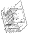
- a housing - for example a control cabinet - is schematically represented by a housing wall 2 and a base 3.
- the device for guiding cables referred to below as cable duct 1, has a frame which is formed on one side and is formed by a rear wall 17, two side walls 7 and 8 and by webs 6 and which is closed by means of an end wall 9, which is connected via Screw connections 15, 16 is detachably connected to the side walls 7 and 8.
- a rear wall 17 of the frame is detachably connected to the housing wall 2 by screws 19 on an outside of the housing wall 2.
- the rear wall 17 covers a housing opening 18 provided for mounting the cable bushing 1 on the housing wall 2 in this housing wall 2 and in turn has a recess 4 through which the cables are inserted into the interior of the housing.
- the frame as a whole is carried by its rear wall 17 attached to the housing wall 2.
- a plurality of cuboidal one-piece filler pieces 10 made of foamed plastic is clamped within the frame.
- 6 spaces are created for this purpose within the frame by means of the webs, in each of which a filler row formed from adjacent filler pieces 10 is fitted, the dimensions of the spaces and filler pieces 10 being matched to one another such that a respective filler piece row under one acting laterally to this Compressive stress is generated, which is generated when a respective filler 10 is inserted into a respective space in the direction of arrow 13. All gaps are completely filled with filler pieces 10.
- the webs have an H-profile that can be seen in the drawing, the legs of which support the filler pieces 10, so that the filler pieces 10 are supported on all sides.
- Exactly one of the number of fillers 10 corresponding to the number of cables to be inserted into the housing is designed as a strain relief block and for this purpose is provided with a longitudinal bore 11 surrounding a cable and a parting line 12.
- the cables outside the housing and outside the frame can thus first be equipped with strain relief blocks, which are then inserted into the respective spaces.
- the side walls 7 and 8 are placed on the bottom 3 of the housing.
- a chamber is created from the rear wall 17, the side walls 7 and 8, the end wall 9, a ceiling closed by means of the filler pieces 10 or the strain relief blocks covered with cables, and a floor plate forming the floor 3, which chamber is only in the area of the recess 4 is open and otherwise closed.
- a seal of the interior of the housing with respect to the recess 4 is thus created in a simple manner. This seal can also be maintained when a cable is removed, if a strain relief block which has become free as a result is replaced by a closed filler 10 or closed by means of a blind plug.
Landscapes
- Engineering & Computer Science (AREA)
- Architecture (AREA)
- Civil Engineering (AREA)
- Structural Engineering (AREA)
- Installation Of Indoor Wiring (AREA)
- Patch Boards (AREA)
Applications Claiming Priority (4)
| Application Number | Priority Date | Filing Date | Title |
|---|---|---|---|
| DE3721484 | 1987-06-30 | ||
| DE3721484 | 1987-06-30 | ||
| DE3816870A DE3816870C2 (de) | 1987-06-30 | 1988-05-18 | Einrichtung zum Durchführen von Kabeln |
| DE3816870 | 1988-05-18 |
Publications (3)
| Publication Number | Publication Date |
|---|---|
| EP0297307A2 EP0297307A2 (de) | 1989-01-04 |
| EP0297307A3 EP0297307A3 (en) | 1990-09-19 |
| EP0297307B1 true EP0297307B1 (de) | 1993-09-08 |
Family
ID=25857079
Family Applications (1)
| Application Number | Title | Priority Date | Filing Date |
|---|---|---|---|
| EP88108882A Expired - Lifetime EP0297307B1 (de) | 1987-06-30 | 1988-06-03 | Einrichtung zur Durchführung von Kabeln |
Country Status (4)
| Country | Link |
|---|---|
| US (1) | US4884774A (https=) |
| EP (1) | EP0297307B1 (https=) |
| JP (1) | JPS6426312A (https=) |
| DE (2) | DE3816870C2 (https=) |
Families Citing this family (18)
| Publication number | Priority date | Publication date | Assignee | Title |
|---|---|---|---|---|
| EP0402653A3 (de) * | 1989-06-13 | 1991-01-16 | Siemens Aktiengesellschaft | Kabeleinführungsdichtung |
| DE8913829U1 (de) * | 1989-11-23 | 1990-01-11 | Brandner, Hans, 8240 Schönau | Vorrichtung zum Abdichten eines Kabeldurchführungsloches in einem Schaltschrank |
| JP2550250Y2 (ja) * | 1990-02-19 | 1997-10-08 | 株式会社 三英社製作所 | 路上設置形配電箱 |
| DE4310117A1 (de) * | 1993-03-27 | 1994-09-29 | Heidelberger Druckmasch Ag | Vorrichtung zur Durchführung von Kabeln |
| GB2299463B (en) * | 1995-03-20 | 1997-06-04 | Woven Electronics Corp | Computer I/O support bracket and cable assembly |
| GB2337870A (en) * | 1998-04-29 | 1999-12-01 | Nokia Telecommunications Oy | Modular cable entry system |
| US6469244B1 (en) * | 2000-06-27 | 2002-10-22 | Cisco Technology, Inc. | EMI cable passthrough shield |
| AU2001214591A1 (en) * | 2000-11-03 | 2002-05-15 | Instrument Specialities Company, Inc. | Modular shielding of openings with passing cables |
| DE10150075A1 (de) * | 2001-10-10 | 2003-04-17 | Roxtec Ingenieur Gmbh | Modulare Schottung zur dichten Durchführung von Kabeln und Rohrleitungen durch Bauteile aller Art (mit nachweisbarer Dichte) |
| KR20070057158A (ko) * | 2004-08-24 | 2007-06-04 | 엠씨티 브라트베르그 악티에볼라그 | 칸막이벽의 설비를 위한 화재 보호 장치 |
| DE102005027771B3 (de) * | 2005-06-15 | 2006-11-30 | Pflitsch Gmbh & Co. Kg | Dichtkörper für Kabeldurchführungen |
| SE531217C2 (sv) * | 2007-05-29 | 2009-01-20 | Roxtec Ab | Kabelgenomföring |
| US20100123048A1 (en) * | 2008-11-18 | 2010-05-20 | Pollard Jr Michael E | Cable bus support block and system |
| US8294030B2 (en) * | 2008-11-18 | 2012-10-23 | MP Husky | Cable bus support block and system |
| EP2538508B1 (en) * | 2011-06-20 | 2016-10-05 | Tyco Electronics Raychem BVBA | Sealing device for feeding through filaments |
| CN104235073A (zh) * | 2014-10-17 | 2014-12-24 | 邢宇 | 在离心泵转动着的空心转子腔体内引入循环流体 |
| DE202017102147U1 (de) * | 2017-04-10 | 2017-05-05 | Igus Gmbh | Leitungsdurchführung, insbesondere Zugentlastung für eine Energieführungskette |
| US11985793B2 (en) * | 2021-01-22 | 2024-05-14 | Dell Products L.P. | Cable sealing apparatus and methods |
Family Cites Families (18)
| Publication number | Priority date | Publication date | Assignee | Title |
|---|---|---|---|---|
| US2732226A (en) * | 1956-01-24 | Brattberg | ||
| US1133976A (en) * | 1913-11-12 | 1915-03-30 | James Kraus | Cable-rack. |
| US2355742A (en) * | 1942-09-21 | 1944-08-15 | Adel Prec Products Corp | Conduit supporting block |
| DE811116C (de) * | 1948-11-23 | 1951-08-16 | Claude Groux | Halterungsstange fuer Draehte, insbesondere fuer elektrische Leiter |
| CH396126A (de) * | 1962-04-09 | 1965-07-31 | Foerderung Forschung Gmbh | Anordnung zum Unterbringen und Befestigen von Kabeln, Schläuchen oder Rohren |
| US3830954A (en) * | 1972-09-28 | 1974-08-20 | Singer Co | Apparatus for shielding against electromagnetic interference |
| DE2431834A1 (de) * | 1974-07-02 | 1976-01-22 | Josef Rocek | Leitungsfuehrung fuer auf wandflaechen zu verlegende kabel oder dgl. |
| JPS5149827U (https=) * | 1974-10-14 | 1976-04-15 | ||
| DE2829887C2 (de) * | 1978-07-07 | 1983-12-29 | Aeg Isolier- Und Kunststoff Gmbh, 3500 Kassel | Verfahren zur Herstellung von wasserdichten und feuerfesten Kabeldurchführungen |
| DD144630A5 (de) * | 1978-07-07 | 1980-10-22 | Licentia Gmbh | Verfahren zur herstellung wasserdichter und feuerfester durchfuehrungen fuer kabel |
| SE415619B (sv) * | 1979-01-18 | 1980-10-13 | Lyckeaborgs Bruk Ab | Genomforing for brandseker forleggning av elektriska kablar genom en oppning i en vegg eller liknande |
| JPS5890008U (ja) * | 1981-12-11 | 1983-06-18 | 株式会社明電舎 | ケ−ブルの押え板 |
| DE8235062U1 (de) * | 1982-12-14 | 1983-06-09 | Rittal-Werk Rudolf Loh Gmbh & Co Kg, 6348 Herborn | Schaltschrank mit einem in mindestens zwei Teilplatten unterteilten Boden |
| AT382045B (de) * | 1984-02-10 | 1986-12-29 | Doepfl Rudolf Gmbh | Einrichtung zur brandgedaemmten durchfuehrung von kabeln od.dgl. durch eine wandoeffnung hindurch |
| JPS60192607U (ja) * | 1984-05-29 | 1985-12-21 | ファナック株式会社 | ケ−ブルクランプ |
| NL8403650A (nl) * | 1984-11-30 | 1986-06-16 | Johannes Alfred Beele | Doorvoerinrichting. |
| EP0223393A3 (en) * | 1985-10-09 | 1989-02-08 | Gec-Marconi Limited | Bulkhead gland assembly |
| DK158865C (da) * | 1986-05-13 | 1990-12-24 | Er Electric As | Fugtspaerrer |
-
1988
- 1988-05-18 DE DE3816870A patent/DE3816870C2/de not_active Expired - Fee Related
- 1988-06-03 EP EP88108882A patent/EP0297307B1/de not_active Expired - Lifetime
- 1988-06-03 DE DE88108882T patent/DE3883867D1/de not_active Expired - Fee Related
- 1988-06-30 US US07/213,550 patent/US4884774A/en not_active Expired - Fee Related
- 1988-06-30 JP JP63161111A patent/JPS6426312A/ja active Granted
Also Published As
| Publication number | Publication date |
|---|---|
| DE3816870C2 (de) | 1993-09-30 |
| JPH0516246B2 (https=) | 1993-03-03 |
| DE3883867D1 (de) | 1993-10-14 |
| JPS6426312A (en) | 1989-01-27 |
| EP0297307A3 (en) | 1990-09-19 |
| DE3816870A1 (de) | 1989-01-12 |
| EP0297307A2 (de) | 1989-01-04 |
| US4884774A (en) | 1989-12-05 |
Similar Documents
| Publication | Publication Date | Title |
|---|---|---|
| EP0297307B1 (de) | Einrichtung zur Durchführung von Kabeln | |
| DE102007018389B4 (de) | Steckverbinder | |
| DE3782832T2 (de) | Durchgang fuer kabel und rohre. | |
| EP2131085A1 (de) | Leitungsdurchführung mit Schichtenfolge | |
| WO1996014729A1 (de) | Schaltschrank mit einem rahmengestell | |
| EP2746634A1 (de) | Kabelhalter mit einem U-förmigen Rahmen und einer Anzahl von Tüllen zum Hindurchführen von Kabeln | |
| DE112009000429T5 (de) | Montagefreundliches Rahmengestell für einen Schaltschrank und dazugehöriges Montageverfahren | |
| EP4111835B1 (de) | Kabeleinlassvorrichtung für einen schaltschrank sowie anordnung und verfahren zum betrieb derselben | |
| DE69507450T2 (de) | Modulare elektrische Reihenklemmenanordnung | |
| WO2021209819A2 (de) | Endbefestigung einer flexiblen umhüllung für reinraumanwendungen | |
| EP3012933A2 (de) | Kabeldurchgangsabdichtung für einen kabelkanal, bausatz für eine kabeldurchgangsabdichtung und verfahren zum montieren einer kabeldurchgangsabdichtung für einen kabelkanal | |
| DE10110689A1 (de) | Gestellkonstruktion eines Gehäuses oder von Gehäusen zur Aufnahme von elektronischen und elektrischen Geräten | |
| DE202004018347U1 (de) | Vorrichtung zur Einführung von Kabeln | |
| DE102020126444A1 (de) | Leitungsdurchführung mit einem Grundrahmen und mit einer Mehrzahl an Leitungsdurchführungsmodulen sowie Verfahren zu deren Montage | |
| DE102013005212A1 (de) | Einrichtung zum Verbinden von mindestens zwei Bauteilen | |
| DE19817633A1 (de) | Schraubmutter | |
| DE2558885B2 (de) | Leitungseinführung an Installationsgehäusen | |
| EP2101384B1 (de) | Leitungsdurchführungssystem durch eine Wandöffnung | |
| DE202021003998U1 (de) | Profilverbinder mit Leitungsdurchführung | |
| DE2618205C3 (de) | Muffeneinsatz | |
| AT516921B1 (de) | Anordnung zur Befestigung eines Koppelelements an einem Wagenkasten eines Fahrzeugs | |
| DE2738321A1 (de) | Verbindungskupplung fuer rohrteile | |
| EP0303194A1 (de) | Profilstange, Eckverbinder sowie Eckverbindung | |
| EP2101383B1 (de) | Leitungsdurchführung durch eine Wandöffnung | |
| DE102024119102A1 (de) | Dichtung und Einschub mit einer solchen zur Abdichtung von Durchführungen eines Hausanschlusskastens |
Legal Events
| Date | Code | Title | Description |
|---|---|---|---|
| PUAI | Public reference made under article 153(3) epc to a published international application that has entered the european phase |
Free format text: ORIGINAL CODE: 0009012 |
|
| 17P | Request for examination filed |
Effective date: 19880603 |
|
| AK | Designated contracting states |
Kind code of ref document: A2 Designated state(s): CH DE FR GB IT LI NL SE |
|
| RIN1 | Information on inventor provided before grant (corrected) |
Inventor name: BLASER, PETER, T.,DIPL.-ING. (FH) Inventor name: RODI, ANTON, DIPL.-ING.(FH) |
|
| PUAL | Search report despatched |
Free format text: ORIGINAL CODE: 0009013 |
|
| AK | Designated contracting states |
Kind code of ref document: A3 Designated state(s): CH DE FR GB IT LI NL SE |
|
| RHK1 | Main classification (correction) |
Ipc: H02G 3/22 |
|
| 17Q | First examination report despatched |
Effective date: 19920818 |
|
| RBV | Designated contracting states (corrected) |
Designated state(s): CH DE FR GB LI |
|
| GRAA | (expected) grant |
Free format text: ORIGINAL CODE: 0009210 |
|
| AK | Designated contracting states |
Kind code of ref document: B1 Designated state(s): CH DE FR GB LI |
|
| REF | Corresponds to: |
Ref document number: 3883867 Country of ref document: DE Date of ref document: 19931014 |
|
| ET | Fr: translation filed | ||
| GBT | Gb: translation of ep patent filed (gb section 77(6)(a)/1977) |
Effective date: 19931110 |
|
| PLBE | No opposition filed within time limit |
Free format text: ORIGINAL CODE: 0009261 |
|
| STAA | Information on the status of an ep patent application or granted ep patent |
Free format text: STATUS: NO OPPOSITION FILED WITHIN TIME LIMIT |
|
| 26N | No opposition filed | ||
| PGFP | Annual fee paid to national office [announced via postgrant information from national office to epo] |
Ref country code: FR Payment date: 19950602 Year of fee payment: 8 |
|
| PGFP | Annual fee paid to national office [announced via postgrant information from national office to epo] |
Ref country code: CH Payment date: 19950808 Year of fee payment: 8 |
|
| PG25 | Lapsed in a contracting state [announced via postgrant information from national office to epo] |
Ref country code: LI Effective date: 19960630 Ref country code: CH Effective date: 19960630 |
|
| REG | Reference to a national code |
Ref country code: CH Ref legal event code: PL |
|
| PG25 | Lapsed in a contracting state [announced via postgrant information from national office to epo] |
Ref country code: FR Effective date: 19970228 |
|
| REG | Reference to a national code |
Ref country code: FR Ref legal event code: ST |
|
| REG | Reference to a national code |
Ref country code: GB Ref legal event code: IF02 |
|
| PGFP | Annual fee paid to national office [announced via postgrant information from national office to epo] |
Ref country code: DE Payment date: 20040709 Year of fee payment: 17 |
|
| PGFP | Annual fee paid to national office [announced via postgrant information from national office to epo] |
Ref country code: GB Payment date: 20050523 Year of fee payment: 18 |
|
| PG25 | Lapsed in a contracting state [announced via postgrant information from national office to epo] |
Ref country code: DE Free format text: LAPSE BECAUSE OF NON-PAYMENT OF DUE FEES Effective date: 20060103 |
|
| PG25 | Lapsed in a contracting state [announced via postgrant information from national office to epo] |
Ref country code: GB Free format text: LAPSE BECAUSE OF NON-PAYMENT OF DUE FEES Effective date: 20060603 |
|
| GBPC | Gb: european patent ceased through non-payment of renewal fee |
Effective date: 20060603 |