EP0297307B1 - Cable feed-through device - Google Patents
Cable feed-through device Download PDFInfo
- Publication number
- EP0297307B1 EP0297307B1 EP88108882A EP88108882A EP0297307B1 EP 0297307 B1 EP0297307 B1 EP 0297307B1 EP 88108882 A EP88108882 A EP 88108882A EP 88108882 A EP88108882 A EP 88108882A EP 0297307 B1 EP0297307 B1 EP 0297307B1
- Authority
- EP
- European Patent Office
- Prior art keywords
- frame
- housing
- rear wall
- wall
- filling pieces
- Prior art date
- Legal status (The legal status is an assumption and is not a legal conclusion. Google has not performed a legal analysis and makes no representation as to the accuracy of the status listed.)
- Expired - Lifetime
Links
Images
Classifications
-
- H—ELECTRICITY
- H02—GENERATION; CONVERSION OR DISTRIBUTION OF ELECTRIC POWER
- H02G—INSTALLATION OF ELECTRIC CABLES OR LINES, OR OF COMBINED OPTICAL AND ELECTRIC CABLES OR LINES
- H02G3/00—Installations of electric cables or lines or protective tubing therefor in or on buildings, equivalent structures or vehicles
- H02G3/22—Installations of cables or lines through walls, floors or ceilings, e.g. into buildings
Definitions
- the invention relates to a device for passing cables through a housing opening in a housing wall into the interior of a housing with a frame supported by the housing wall and a plurality of cuboidal one-piece fillers made of foamed plastic braced within the frame and supported on all sides, at least some of which are by whose equipment with a longitudinal hole surrounding a cable and a joint serve as a respective strain relief block for each cable.
- Such a device is known for example from the document EP 0 223 393 A2.
- ends of cables to be inserted into a housing are in certain cases equipped with relatively bulky coupling devices, by means of which the cables can be connected quickly and easily to corresponding counterparts in the housing.
- a correspondingly quick and easy removal of a cable from the housing now also requires a cable passage through the housing wall, which offers sufficient space for the relatively bulky coupling devices to pass through.
- this free space is determined, on the one hand, during assembly by the opening formed with the frame and, if only a few cables are passed through, can therefore be smaller than would be necessary to pass a coupling device. On the other hand, only one cable would have to be dismantled Possible repair purposes within the frame space for a coupling device may be created by completely removing all filler pieces.
- the fillers used in the known device which serve as strain relief blocks, are also known from the document FR 2 537 794 A1. They have a cuboid shape, a longitudinal bore enclosing a cable and a parting line in a plane containing the axis of symmetry of the longitudinal bore.
- the invention is intended to propose a device for passing cables through a housing opening in a housing wall into the interior of a housing, which on the one hand is easy to assemble and on the other hand enables the fitting of cable ends with any desired coupling devices.
- a generic device is designed in such a way that the frame has a rear wall that supports it, which is detachably connected to the outside of the housing wall, covers the housing opening and has a recess, the frame projects into the interior of the housing, and the cables are inserted through the recess into the interior of the housing.
- the strain relief blocks for receiving the cables can be provided with longitudinal bores of different sizes, so that the device can be used for cables of different diameters without the outer dimensions of the cuboid strain relief blocks being different.
- Another advantage is the fact that the cables can be loosened or replaced at any time, because due to the secure hold of the cable in a strain relief block, an inseparable connection, for example by gluing or filling in an additional potting compound, is not necessary.
- the frame has webs that run perpendicular to the rear wall and are fixedly connected to it, arranged between side walls of the frame, and gaps created by means of the webs within the frame are filled with fillers lined up to form a row of filler pieces.
- these can also have other structures for supporting the filler pieces, such as a toothed structure, the profile of the structure running in the direction of a sliding movement for mounting the filler piece.
- the longitudinal bore of a strain relief block is provided with a diameter that is slightly smaller than the outer diameter of a cable that is passed through this longitudinal bore, this helps to establish a non-slip, dust and splash-proof connection between the strain relief block and the cable located therein.
- the device is therefore particularly suitable for control cabinets that have to meet these conditions.
- a further embodiment of the invention provides that in the case of a large number of filling pieces, those which do not serve as strain relief blocks are designed as so-called blind cuboids, ie these filler pieces have no longitudinal bore or their longitudinal bore is closed with a blind plug.
- the arrangement of such blind plugs also enables cables to be inserted subsequently in a particularly simple manner.
- strain relief blocks so that they form a common block. This then has a plurality of longitudinal bores, each with separating joints assigned to them.
- the frame is closed by means of an end wall which is releasably connectable to its side walls and which lies opposite the rear wall and presses a respective row of filler pieces against the rear wall.
- the filler pieces can be easily clamped within the frame.
- the dimensions of the intermediate spaces and the filler pieces are matched to one another in an advantageous embodiment such that a respective row of filler pieces inserted into an intermediate space is under a compressive stress acting laterally thereon.
- the interior of the housing, into which the cables are inserted by means of the device is sealed off from the recess provided in the rear wall thereof.
- an open and otherwise closed chamber is formed in the region of the recess.
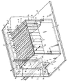
- a housing - for example a control cabinet - is schematically represented by a housing wall 2 and a base 3.
- the device for guiding cables referred to below as cable duct 1, has a frame which is formed on one side and is formed by a rear wall 17, two side walls 7 and 8 and by webs 6 and which is closed by means of an end wall 9, which is connected via Screw connections 15, 16 is detachably connected to the side walls 7 and 8.
- a rear wall 17 of the frame is detachably connected to the housing wall 2 by screws 19 on an outside of the housing wall 2.
- the rear wall 17 covers a housing opening 18 provided for mounting the cable bushing 1 on the housing wall 2 in this housing wall 2 and in turn has a recess 4 through which the cables are inserted into the interior of the housing.
- the frame as a whole is carried by its rear wall 17 attached to the housing wall 2.
- a plurality of cuboidal one-piece filler pieces 10 made of foamed plastic is clamped within the frame.
- 6 spaces are created for this purpose within the frame by means of the webs, in each of which a filler row formed from adjacent filler pieces 10 is fitted, the dimensions of the spaces and filler pieces 10 being matched to one another such that a respective filler piece row under one acting laterally to this Compressive stress is generated, which is generated when a respective filler 10 is inserted into a respective space in the direction of arrow 13. All gaps are completely filled with filler pieces 10.
- the webs have an H-profile that can be seen in the drawing, the legs of which support the filler pieces 10, so that the filler pieces 10 are supported on all sides.
- Exactly one of the number of fillers 10 corresponding to the number of cables to be inserted into the housing is designed as a strain relief block and for this purpose is provided with a longitudinal bore 11 surrounding a cable and a parting line 12.
- the cables outside the housing and outside the frame can thus first be equipped with strain relief blocks, which are then inserted into the respective spaces.
- the side walls 7 and 8 are placed on the bottom 3 of the housing.
- a chamber is created from the rear wall 17, the side walls 7 and 8, the end wall 9, a ceiling closed by means of the filler pieces 10 or the strain relief blocks covered with cables, and a floor plate forming the floor 3, which chamber is only in the area of the recess 4 is open and otherwise closed.
- a seal of the interior of the housing with respect to the recess 4 is thus created in a simple manner. This seal can also be maintained when a cable is removed, if a strain relief block which has become free as a result is replaced by a closed filler 10 or closed by means of a blind plug.
Description
Die Erfindung betrifft eine Einrichtung zum Durchführen von Kabeln durch eine Gehäuseöffnung in einer Gehäusewand in das Innere eines Gehäuses mit einem von der Gehäusewand getragenen Rahmen und einer Mehrzahl von innerhalb des Rahmens verspannten, allseitig abgestützten quaderförmigen einstückigen Füllstücken aus aufgeschäumtem Kunststoff, von welchen zumindest einzelne durch deren Ausstattung mit einer ein Kabel umschließenden Längsbohrung und einer Trennfuge als jeweiliger Zugentlastungsblock für ein jeweiliges Kabel dienen.The invention relates to a device for passing cables through a housing opening in a housing wall into the interior of a housing with a frame supported by the housing wall and a plurality of cuboidal one-piece fillers made of foamed plastic braced within the frame and supported on all sides, at least some of which are by whose equipment with a longitudinal hole surrounding a cable and a joint serve as a respective strain relief block for each cable.
Eine derartige Einrichtung ist beispielsweise aus der Druckschrift EP 0 223 393 A2 bekannt.Such a device is known for example from the document EP 0 223 393 A2.
In der Praxis sind in ein Gehäuse einzuführende Enden von Kabeln in bestimmten Fällen mit relativ sperrigen Kupplungsvorrichtungen bestückt, mittels welcher ein schneller und unkomplizierter Anschluß der Kabel an entsprechenden Gegenstücken im Gehäuse erfolgen kann. Ein entsprechend schnelles und leichtes Entfernen eines Kabels aus dem Gehäuse erfordert nun aber auch eine Kabeldurchführung durch die Gehäusewand, die einen ausreichenden Freiraum zum Hindurchführen der relativ sperrigen Kupplungsvorrichtungen bietet.In practice, ends of cables to be inserted into a housing are in certain cases equipped with relatively bulky coupling devices, by means of which the cables can be connected quickly and easily to corresponding counterparts in the housing. A correspondingly quick and easy removal of a cable from the housing now also requires a cable passage through the housing wall, which offers sufficient space for the relatively bulky coupling devices to pass through.
Bei der bekannten Einrichtung ist dieser Freiraum einerseits bei der Montage durch die mit dem Rahmen gebildete Öffnung bestimmt und kann daher im Falle der Durchführung von nur wenigen Kabeln unter Umständen kleiner sein als zum Hindurchführen einer Kupplungsvorrichtung notwendig wäre. Zum anderen müßte bei einer Demontage nur eines Kabels zu eventuellen Reparaturzwecken innerhalb des Rahmens Platz für eine Kupplungsvorrichtung gegebenenfalls durch völliges Entfernen aller Füllstücke geschaffen werden.In the known device, this free space is determined, on the one hand, during assembly by the opening formed with the frame and, if only a few cables are passed through, can therefore be smaller than would be necessary to pass a coupling device. On the other hand, only one cable would have to be dismantled Possible repair purposes within the frame space for a coupling device may be created by completely removing all filler pieces.
Die bei der bekannten Einrichtung verwendeten, als Zugentlastungsblöcke dienenden Füllstücke sind im übrigen auch aus der Druckschrift FR 2 537 794 A1 bekannt. Sie besitzen eine quaderförmige Gestalt, eine ein Kabel umschließende Längsbohrung und eine Trennfuge in einer die Symmetrieachse der Längsbohrung enthaltenden Ebene.The fillers used in the known device, which serve as strain relief blocks, are also known from the document FR 2 537 794 A1. They have a cuboid shape, a longitudinal bore enclosing a cable and a parting line in a plane containing the axis of symmetry of the longitudinal bore.
Mit der Erfindung soll eine Einrichtung zum Durchführen von Kabeln durch eine Gehäuseöffnung in einer Gehäusewand in das Innere eines Gehäuses vorgeschlagen werden, die einerseits leicht montierbar ist und andererseits die Bestückung von Kabelenden mit beliebig gestalteten Kupplungsvorrichtungen ermöglicht.The invention is intended to propose a device for passing cables through a housing opening in a housing wall into the interior of a housing, which on the one hand is easy to assemble and on the other hand enables the fitting of cable ends with any desired coupling devices.
Erfindungsgemäß ist hierzu eine gattungsgemäße Einrichtung derart ausgebildet, daß der Rahmen eine diesen tragende Rückwand aufweist, welche an einer Außenseite der Gehäusewand lösbar mit dieser verbunden ist, die Gehäuseöffnung überdeckt und eine Aussparung aufweist, der Rahmen in das Innere des Gehäuses hineinragt, und die Kabel durch die Aussparung in das Innere des Gehäuses eingeführt sind.According to the invention, a generic device is designed in such a way that the frame has a rear wall that supports it, which is detachably connected to the outside of the housing wall, covers the housing opening and has a recess, the frame projects into the interior of the housing, and the cables are inserted through the recess into the interior of the housing.
Ein wesentlicher Vorteil einer erfindungsgemäßen Einrichtung besteht darin, daß nunmehr vorkonfektionierte, mit Steckem beliebiger Größe versehene Kabel in diese Einrichtung vormontiert werden können. Die Zugentlastungsblöcke zur Aufnahme der Kabel können mit Längsbohrungen unterschiedlicher Größe versehen sein, so daß die Einrichtung für Kabelverschiedener Durchmesser verwendbar ist, ohne daß die äußeren Abmessungen der quaderförmigen Zugentlastungsblöcke unterschiedlich sind.An important advantage of a device according to the invention is that it is now possible to preassemble cables with any size of connector in this device. The strain relief blocks for receiving the cables can be provided with longitudinal bores of different sizes, so that the device can be used for cables of different diameters without the outer dimensions of the cuboid strain relief blocks being different.
Ein weiterer Vorteil ist darin zu sehen, daß die Kabel jederzeit gelöst, bzw. ausgetauscht werden können, da aufgrund des sicheren Haltes des Kabels in einem Zugentlastungsblock eine unlösbare Verbindung, beispielsweise durch Kleben oder Einfüllen einer zusätzlichen Vergußmasse nicht erforderlich ist.Another advantage is the fact that the cables can be loosened or replaced at any time, because due to the secure hold of the cable in a strain relief block, an inseparable connection, for example by gluing or filling in an additional potting compound, is not necessary.
In vorteilhafter Ausgestaltung weist der Rahmen senkrecht zur Rückwand verlaufende und mit dieser fest verbundene, zwischen Seitenwänden des Rahmens angeordnete Stege auf und mittels der Stege innerhalb des Rahmens geschaffene Zwischenräume sind mit jeweils zu einer Füllstückreihe aneinandergereihten Füllstücken ausgefüllt.In an advantageous embodiment, the frame has webs that run perpendicular to the rear wall and are fixedly connected to it, arranged between side walls of the frame, and gaps created by means of the webs within the frame are filled with fillers lined up to form a row of filler pieces.
Damit besteht in bestimmten Fällen die Möglichkeit einer Ergänzung, einer Entfernung oder eines Austauschs ohne eine völlige Demontage der Einrichtung. Solche Fälle liegen beispielsweise vor, wenn entsprechende Umrüstungen insbesondere auf einen der Zwischenräume beschränkt sind. Anstelle einer bekannten H-förmigen Ausbildung der Stege können diese zur Abstützung der Füllstücke auch andere Strukturen aufweisen, wie beispielsweise eine gezahnte Struktur, wobei das Profil der Struktur in Richtung einer Schiebebewegung zur Montage der Füllstück verläuft.In certain cases, this means that it is possible to add, remove or replace them without completely dismantling the device. Such cases exist, for example, when appropriate conversions are limited in particular to one of the spaces. Instead of a known H-shaped design of the webs, these can also have other structures for supporting the filler pieces, such as a toothed structure, the profile of the structure running in the direction of a sliding movement for mounting the filler piece.
Wird die Längsbohrung eines Zugentlastungsblocks mit einem Durchmesser versehen, der etwas geringer als der Außendurchmesser eines durch diese Längsbohrung hindurchgeführten Kabels ist, so trägt dies dazu bei, eine rutschfeste, staub- und spritzwassergeschützte Verbindung zwischen dem Zugentlastungsblock und dem darin befindlichen Kabel herzustellen. Die Einrichtung eignet sich damit insbesondere für Schaltschränke, welche diese Bedingungen erfüllen müssen.If the longitudinal bore of a strain relief block is provided with a diameter that is slightly smaller than the outer diameter of a cable that is passed through this longitudinal bore, this helps to establish a non-slip, dust and splash-proof connection between the strain relief block and the cable located therein. The device is therefore particularly suitable for control cabinets that have to meet these conditions.
Eine weitere Ausgestaltung der Erfindung sieht vor, bei einer Vielzahl von Füllstücken solche, die nicht als Zugentlastungsblöcke dienen, als sogenannte Blindquader auszubilden, d.h. diese Füllstücke weisen keine Längsbohrung auf bzw. deren Längsbohrung ist mit einem Blindstopfen verschlossen. Durch die Anordnung solcher Blindstopfen ist auch das nachträgliche Einfügen von Kabeln in besonders einfacher Weise möglich.A further embodiment of the invention provides that in the case of a large number of filling pieces, those which do not serve as strain relief blocks are designed as so-called blind cuboids, ie these filler pieces have no longitudinal bore or their longitudinal bore is closed with a blind plug. The arrangement of such blind plugs also enables cables to be inserted subsequently in a particularly simple manner.
Es besteht auch die Möglichkeit, mehrere Zugentlastungsblöcke zusammenzufassen, so daß diese einen gemeinsamen Block bilden. Dieser weist dann mehrere Längsbohrungen mit jeweils diesen zugeordneten Trennfugen auf.It is also possible to combine several strain relief blocks so that they form a common block. This then has a plurality of longitudinal bores, each with separating joints assigned to them.
In weiterer Ausgestaltung ist der Rahmen mittels einer lösbar mit dessen Seitenwänden verbindbaren, der Rückwand gegenüberliegenden Stirnwand geschlossen, welche eine jeweilige Füllstückreihe gegen die Rückwand preßt.In a further embodiment, the frame is closed by means of an end wall which is releasably connectable to its side walls and which lies opposite the rear wall and presses a respective row of filler pieces against the rear wall.
Damit sind die Füllstücke auf einfache Weise innerhalb des Rahmens verspannbar. Als eine weitere Maßnahme zur Verspannung der Füllstücke innerhalb des Rahmens sind in vorteilhafter Ausgestaltung die Abmessungen der Zwischenräume und der Füllstücke so aufeinander abgestimmt, daß eine jeweilige in einen Zwischenraum eingeschobene Füllstückreihe unter einer seitlich hierauf wirkenden Druckspannung steht.So that the filler pieces can be easily clamped within the frame. As a further measure for bracing the filler pieces within the frame, the dimensions of the intermediate spaces and the filler pieces are matched to one another in an advantageous embodiment such that a respective row of filler pieces inserted into an intermediate space is under a compressive stress acting laterally thereon.
Bei einer vorteilhaften Ausbildung ist das Innere des Gehäuses, in welche die Kabel mittels der Einrichtung eingeführt werden, gegenüber der in deren Rückwand vorgesehenen Aussparung abgedichtet. Hierbei ist aus der Rückwand, aus Seitenwänden des Rahmens, aus einer der Rückwand gegenüberliegenden, den Rahmen schließenden Stirnwand, aus einer mittels der Füllstücke gebildeten geschlossenen Decke und aus einer dieser gegenüberliegenden Bodenplatte eine im Bereich der Aussparung offene und im übrigen geschlossene Kammer gebildet.In an advantageous embodiment, the interior of the housing, into which the cables are inserted by means of the device, is sealed off from the recess provided in the rear wall thereof. In this case, from the rear wall, from side walls of the frame, from an end wall opposite the rear wall, which closes the frame, from a closed ceiling formed by the fillers and from a floor plate opposite this, an open and otherwise closed chamber is formed in the region of the recess.
Ein Ausführungsbeispiel des Erfindungsgegenstands ist in der nachfolgend erläuterten Zeichnung dargestellt.An embodiment of the subject matter of the invention is shown in the drawing explained below.
Hierin ist ein Gehäuse - beispielsweise eines Schaltschranks - schematisch durch eine Gehäusewand 2 und einen Boden 3 dargestellt. Die im folgenden kurz Kabeldurchführung 1 benannte Einrichtung zum Durchführen von Kabeln weist einen mit einer Rückwand 17, zwei Seitenwänden 7 und 8 sowie mit Stegen 6 gebildeten, einseitig offenen Rahmen auf, der mittels einer Stirnwand 9 geschlossen ist, welche über Schraubenverbindungen 15, 16 lösbar mit den Seitenwänden 7 und 8 verbunden ist.Here, a housing - for example a control cabinet - is schematically represented by a housing wall 2 and a base 3. The device for guiding cables, referred to below as cable duct 1, has a frame which is formed on one side and is formed by a
Eine Rückwand 17 des Rahmens ist an einer Außenseite der Gehäusewand 2 mittels Schrauben 19 lösbar mit der Gehäusewand 2 verbunden. Die Rückwand 17 überdeckt dabei eine zur Montage der Kabeldurchführung 1 an der Gehäusewand 2 in dieser Gehäusewand 2 vorgesehene Gehäuseöffnung 18 und weist ihrerseits eine Aussparung 4 auf, durch welche die Kabel in das Innere des Gehäuses eingeführt sind. Die senkrecht zur Rückwand 17 verlaufenden und mit dieser fest verbundenen Seitenwände 7 und 8 und Stege 6 ragen in das Innere des Gehäuses hinein. Somit wird der Rahmen insgesamt von dessen an der Gehäusewand 2 befestigten Rückwand 17 getragen.A
Innerhalb des Rahmens ist eine Mehrzahl von quaderförmigen einstückigen Füllstücken 10 aus aufgeschäumtem Kunststoff verspannt. Beim Ausführungsbeispiel sind hierzu innerhalb des Rahmens mittels der Stege 6 Zwischenräume geschaffen, in welchen jeweils eine aus aneinandergereihten Füllstücken 10 gebildete Füllstückreihe eingepaßt ist, wobei die Abmessungen der Zwischenräume und der Füllstücke 10 so aufeinander abgestimmt sind, daß eine jeweilige Füllstückreihe unter einer seitlich hierzu wirkenden Druckspannung steht, die beim Einschieben eines jeweiligen Füllstücks 10 in einen jeweiligen Zwischenraum in Richtung des Pfeils 13 erzeugt wird. Dabei sind alle Zwischenräume vollständig mit Füllstücken 10 ausgefüllt.A plurality of cuboidal one-
Eine Alternative oder auch zusätzliche Möglichkeit zum Vorspannen der Füllstücke 10 innerhalb des Rahmens ist dadurch gegeben, daß eine jeweilige Füllstückreihe die freien Enden der sie einschließenden Stege 6 vor dem Anbringen der Stirnwand 9 überragt, so daß eine jeweilige Füllstückreihe mittels der Stirnwand 9 gegen die Rückwand 17 gepreßt wird.An alternative or additional possibility for prestressing the
Die Stege weisen ein aus der Zeichnung ersichtliches H-Profil auf, dessen Schenkel die Füllstücke 10 abstützen, so daß die Füllstücke 10 insgesamt allseitig abgestützt sind.The webs have an H-profile that can be seen in the drawing, the legs of which support the
Vorzugsweise ist genau eine der Anzahl der in das Gehäuse einzuführenden Kabel entsprechende Anzahl der Füllstücke 10 als Zugentlastungsblock ausgebildet und hierzu mit einer ein Kabel umschließenden Längsbohrung 11 und einer Trennfuge 12 versehen. Bei der Montage der erfindungsgemäßen Einrichtung können somit die Kabel außerhalb des Gehäuses und außerhalb des Rahmens zunächst mit Zugentlastungsblöcken bestückt werden, welche anschließend in jeweilige Zwischenräume eingeschoben werden.Exactly one of the number of
Im dargestellten Ausführungsbeispiel sind die Seitenwände 7 und 8 auf den Boden 3 des Gehäuses aufgesetzt. Damit ist aus der Rückwand 17, den Seitenwänden 7 und 8, der Stirnwand 9, einer mittels der Füllstücke 10 bzw. der mit Kabeln belegten Zugentlastungsblöcke geschlossenen Decke und aus einer den Boden 3 bildenden Bodenplatte eine Kammer geschaffen, die lediglich im Bereich der Aussparung 4 offen und im übrigen geschlossen ist. Damit ist auf einfache Weise eine Abdichtung des Innenraumes des Gehäuses gegenüber der Aussparung 4 geschaffen. Diese Abdichtung kann auch beim eventuellen Entfernen eines Kabels aufrechterhalten werden, wenn ein dadurch frei gewordener Zugentlastungsblock durch ein geschlossenes Füllstück 10 ersetzt oder mittels eines Blindstopfens verschlossen wird.In the illustrated embodiment, the
Claims (6)
- Device for running cables (5) through a housing opening (18) in a housing wall (2) into the interior of a housing, having- a frame supported by the housing wall (2)
and- a plurality of cuboid-shaped, one-piece filling pieces (10), made of foamed plastic, which are braced within the frame and are supported on all sides and at least some of which, by virtue of being equipped with a longitudinal bore (11) enclosing a cable (5) and with a parting line (12), act as a respective traction-relieving block for a respective cable (5),
characterised in that- the frame exhibits a rear wall (17) which supports the said frame and which, on an outer side of the housing wall (2), is detachably connected to the latter, covers the housing opening (18) and exhibits a recess (4),- the frame protrudes into the interior of the housing
and- the cables (5) are guided by the recess (4) into the interior of the housing. - Device according to Claim 1, characterised in that- the frame exhibits crosspieces (6) which run perpendicularly to the rear wall (17) and are firmly connected thereto and which are disposed between side walls (7, 8) of the frame
and- respective interspaces created within the frame by means of the crosspieces (6) are filled with filling pieces (10) which are respectively lined up to form a row of filling pieces. - Device according to Claim 2, characterised in that the frame is closed by means of an end wall (9) which is detachably connectable to the side walls (7, 8) of the said frame and lies opposite the rear wall (17) and which presses a respective row of filling pieces against the rear wall (17).
- Device according to Claim 1, characterised in that the longitudinal bore (11) of a filling piece (10) configured as a traction-relieving block is closed off by means of a dummy plug.
- Device according to Claim 2, characterised in that the dimensions of the interspaces and of the filling pieces (10) are mutually coordinated such that a respective row of filling pieces inserted into an interspace is subjected to a compressive strain acting laterally thereupon.
- Device according to Claim 1, characterised in that a chamber which is open in the area of the recess (4) and is otherwise closed is formed from the rear wall (17), from the side walls (7, 8) of the frame, from an end wall (9) lying opposite the rear wall (17) and closing the frame, from a closed ceiling formed by means of the filling pieces (10) and from a floor (3) lying opposite the said ceiling.
Applications Claiming Priority (4)
| Application Number | Priority Date | Filing Date | Title |
|---|---|---|---|
| DE3721484 | 1987-06-30 | ||
| DE3721484 | 1987-06-30 | ||
| DE3816870 | 1988-05-18 | ||
| DE3816870A DE3816870C2 (en) | 1987-06-30 | 1988-05-18 | Device for the passage of cables |
Publications (3)
| Publication Number | Publication Date |
|---|---|
| EP0297307A2 EP0297307A2 (en) | 1989-01-04 |
| EP0297307A3 EP0297307A3 (en) | 1990-09-19 |
| EP0297307B1 true EP0297307B1 (en) | 1993-09-08 |
Family
ID=25857079
Family Applications (1)
| Application Number | Title | Priority Date | Filing Date |
|---|---|---|---|
| EP88108882A Expired - Lifetime EP0297307B1 (en) | 1987-06-30 | 1988-06-03 | Cable feed-through device |
Country Status (4)
| Country | Link |
|---|---|
| US (1) | US4884774A (en) |
| EP (1) | EP0297307B1 (en) |
| JP (1) | JPS6426312A (en) |
| DE (2) | DE3816870C2 (en) |
Families Citing this family (18)
| Publication number | Priority date | Publication date | Assignee | Title |
|---|---|---|---|---|
| EP0402653A3 (en) * | 1989-06-13 | 1991-01-16 | Siemens Aktiengesellschaft | Cable inlet seal |
| DE8913829U1 (en) * | 1989-11-23 | 1990-01-11 | Brandner, Hans, 8240 Schoenau, De | |
| JP2550250Y2 (en) * | 1990-02-19 | 1997-10-08 | 株式会社 三英社製作所 | On-road distribution box |
| DE4310117A1 (en) * | 1993-03-27 | 1994-09-29 | Heidelberger Druckmasch Ag | Device for the passage of cables |
| GB2299463B (en) * | 1995-03-20 | 1997-06-04 | Woven Electronics Corp | Computer I/O support bracket and cable assembly |
| GB2337870A (en) * | 1998-04-29 | 1999-12-01 | Nokia Telecommunications Oy | Modular cable entry system |
| US6469244B1 (en) * | 2000-06-27 | 2002-10-22 | Cisco Technology, Inc. | EMI cable passthrough shield |
| WO2002037920A1 (en) * | 2000-11-03 | 2002-05-10 | Instrument Specialities Company, Inc. | Modular shielding of openings with passing cables |
| DE10150075A1 (en) * | 2001-10-10 | 2003-04-17 | Roxtec Ingenieur Gmbh | Module for a sealed passage for cables/pipes, through constructions, has a lateral recess around its outer sealing surfaces with at least one drilling to the interior to test the hermetic sealing |
| DK1782514T3 (en) * | 2004-08-24 | 2009-08-17 | Mct Brattberg Ab | Fire protection device for installation in a partition |
| DE102005027771B3 (en) * | 2005-06-15 | 2006-11-30 | Pflitsch Gmbh & Co. Kg | Prefabricated cable feed through sealing body for switchboard, has bodies lying on top of one another with surfaces that are in wave or meander shape and joined, where wave or meander progress is directed parallel to cable direction |
| SE531217C2 (en) * | 2007-05-29 | 2009-01-20 | Roxtec Ab | Cable entry |
| US8294030B2 (en) * | 2008-11-18 | 2012-10-23 | MP Husky | Cable bus support block and system |
| US20100123048A1 (en) * | 2008-11-18 | 2010-05-20 | Pollard Jr Michael E | Cable bus support block and system |
| ES2608676T3 (en) * | 2011-06-20 | 2017-04-12 | Tyco Electronics Raychem Bvba | Closing device for feeding through filaments |
| CN104235073A (en) * | 2014-10-17 | 2014-12-24 | 邢宇 | Method for introducing circulating fluid into rotating hollow rotor cavity of centrifugal pump |
| DE202017102147U1 (en) * | 2017-04-10 | 2017-05-05 | Igus Gmbh | Cable bushing, in particular strain relief for an energy chain |
| US20220240409A1 (en) * | 2021-01-22 | 2022-07-28 | Dell Products L.P. | Cable Sealing Apparatus And Methods |
Family Cites Families (18)
| Publication number | Priority date | Publication date | Assignee | Title |
|---|---|---|---|---|
| US2732226A (en) * | 1956-01-24 | Brattberg | ||
| US1133976A (en) * | 1913-11-12 | 1915-03-30 | James Kraus | Cable-rack. |
| US2355742A (en) * | 1942-09-21 | 1944-08-15 | Adel Prec Products Corp | Conduit supporting block |
| DE811116C (en) * | 1948-11-23 | 1951-08-16 | Claude Groux | Support bar for wires, especially for electrical conductors |
| CH396126A (en) * | 1962-04-09 | 1965-07-31 | Foerderung Forschung Gmbh | Arrangement for accommodating and fastening cables, hoses or pipes |
| US3830954A (en) * | 1972-09-28 | 1974-08-20 | Singer Co | Apparatus for shielding against electromagnetic interference |
| DE2431834A1 (en) * | 1974-07-02 | 1976-01-22 | Josef Rocek | Wall mounting multi-layer cable support bracket - has sprung flanged ends to assist in retaining cables |
| JPS5149827U (en) * | 1974-10-14 | 1976-04-15 | ||
| DE2829887C2 (en) * | 1978-07-07 | 1983-12-29 | Aeg Isolier- Und Kunststoff Gmbh, 3500 Kassel | Process for the production of watertight and fireproof cable bushings |
| DD144630A5 (en) * | 1978-07-07 | 1980-10-22 | Licentia Gmbh | METHOD FOR PRODUCING WATERPROOF AND FIRE-RESISTANT TRANSMISSIONS FOR CABLES |
| SE415619B (en) * | 1979-01-18 | 1980-10-13 | Lyckeaborgs Bruk Ab | TRANSFER FOR FIRE SAFETY PRESENTATION OF ELECTRICAL CABLES THROUGH A WALL OR SIMILAR OPENING |
| JPS5890008U (en) * | 1981-12-11 | 1983-06-18 | 株式会社明電舎 | Cable holding plate |
| DE8235062U1 (en) * | 1982-12-14 | 1983-06-09 | Rittal-Werk Rudolf Loh Gmbh & Co Kg, 6348 Herborn | Control cabinet with a base divided into at least two sub-panels |
| AT382045B (en) * | 1984-02-10 | 1986-12-29 | Doepfl Rudolf Gmbh | DEVICE FOR FIRE-INSULATED THROUGHOUT OF CABLES OR THE LIKE. THROUGH A WALL OPENING |
| JPS60192607U (en) * | 1984-05-29 | 1985-12-21 | ファナック株式会社 | cable clamp |
| NL8403650A (en) * | 1984-11-30 | 1986-06-16 | Johannes Alfred Beele | TRANSIT DEVICE. |
| GB2181902B (en) * | 1985-10-09 | 1989-09-27 | Plessey Co Plc | Bulkhead gland assembly |
| DK158865C (en) * | 1986-05-13 | 1990-12-24 | Er Electric As | MOISTURE LOCKS |
-
1988
- 1988-05-18 DE DE3816870A patent/DE3816870C2/en not_active Expired - Fee Related
- 1988-06-03 EP EP88108882A patent/EP0297307B1/en not_active Expired - Lifetime
- 1988-06-03 DE DE88108882T patent/DE3883867D1/en not_active Expired - Fee Related
- 1988-06-30 JP JP63161111A patent/JPS6426312A/en active Granted
- 1988-06-30 US US07/213,550 patent/US4884774A/en not_active Expired - Fee Related
Also Published As
| Publication number | Publication date |
|---|---|
| DE3816870A1 (en) | 1989-01-12 |
| DE3816870C2 (en) | 1993-09-30 |
| JPH0516246B2 (en) | 1993-03-03 |
| DE3883867D1 (en) | 1993-10-14 |
| JPS6426312A (en) | 1989-01-27 |
| EP0297307A3 (en) | 1990-09-19 |
| US4884774A (en) | 1989-12-05 |
| EP0297307A2 (en) | 1989-01-04 |
Similar Documents
| Publication | Publication Date | Title |
|---|---|---|
| EP0297307B1 (en) | Cable feed-through device | |
| DE102007018389B4 (en) | Connectors | |
| EP2131085B1 (en) | Conduit lead through with sequence of layers | |
| EP0789985A1 (en) | Switchgear cabinet with frame | |
| EP2746634A1 (en) | Cable holder with a U-Shape frame and multiple sockets for the leadthrough of cables | |
| DE112009000429T5 (en) | Easy-to-mount frame for a control cabinet and associated mounting procedure | |
| DE102014215254A1 (en) | Carrying or holding frame | |
| DE10110689A1 (en) | Frame construction of a housing or of housings for receiving electronic and electrical devices | |
| DE3043344A1 (en) | CONNECTING DEVICE FOR PNEUMATIC DEVICES | |
| DE3816516A1 (en) | SOCKET FOR A CONTROL CABINET OR THE LIKE | |
| DE10142628A1 (en) | Closing and sealing element | |
| DE202004018347U1 (en) | Cable-inserting device for ready-made cabling on plugs for appliances has a multi-part plate with an opening for leading through ready-made cabling | |
| DE102013005212A1 (en) | Device for connecting at least two components | |
| CH698033B1 (en) | Housing with the housing aperture covering bezel. | |
| DE102020126444A1 (en) | Cable bushing with a base frame and with a plurality of cable bushing modules and method for their assembly | |
| DE19817633A1 (en) | Ring nut for pipe union made in two interlocking halves | |
| DE2558885B2 (en) | Cable entry on installation housings | |
| EP2101384B1 (en) | System of leading a cable duct through an opening in a wall | |
| DE2618205C3 (en) | Socket insert | |
| DE602004011058T2 (en) | covering | |
| AT516921B1 (en) | Arrangement for fastening a coupling element to a car body of a vehicle | |
| DE2738321A1 (en) | CONNECTING COUPLING FOR PIPE PARTS | |
| EP2101383B1 (en) | Cable duct through an opening in a wall | |
| EP0303194A1 (en) | Bar, corner connector and corner connection | |
| DE202021003998U1 (en) | Profile connector with cable bushing |
Legal Events
| Date | Code | Title | Description |
|---|---|---|---|
| PUAI | Public reference made under article 153(3) epc to a published international application that has entered the european phase |
Free format text: ORIGINAL CODE: 0009012 |
|
| 17P | Request for examination filed |
Effective date: 19880603 |
|
| AK | Designated contracting states |
Kind code of ref document: A2 Designated state(s): CH DE FR GB IT LI NL SE |
|
| RIN1 | Information on inventor provided before grant (corrected) |
Inventor name: BLASER, PETER, T.,DIPL.-ING. (FH) Inventor name: RODI, ANTON, DIPL.-ING.(FH) |
|
| PUAL | Search report despatched |
Free format text: ORIGINAL CODE: 0009013 |
|
| AK | Designated contracting states |
Kind code of ref document: A3 Designated state(s): CH DE FR GB IT LI NL SE |
|
| RHK1 | Main classification (correction) |
Ipc: H02G 3/22 |
|
| 17Q | First examination report despatched |
Effective date: 19920818 |
|
| RBV | Designated contracting states (corrected) |
Designated state(s): CH DE FR GB LI |
|
| GRAA | (expected) grant |
Free format text: ORIGINAL CODE: 0009210 |
|
| AK | Designated contracting states |
Kind code of ref document: B1 Designated state(s): CH DE FR GB LI |
|
| REF | Corresponds to: |
Ref document number: 3883867 Country of ref document: DE Date of ref document: 19931014 |
|
| ET | Fr: translation filed | ||
| GBT | Gb: translation of ep patent filed (gb section 77(6)(a)/1977) |
Effective date: 19931110 |
|
| PLBE | No opposition filed within time limit |
Free format text: ORIGINAL CODE: 0009261 |
|
| STAA | Information on the status of an ep patent application or granted ep patent |
Free format text: STATUS: NO OPPOSITION FILED WITHIN TIME LIMIT |
|
| 26N | No opposition filed | ||
| PGFP | Annual fee paid to national office [announced via postgrant information from national office to epo] |
Ref country code: FR Payment date: 19950602 Year of fee payment: 8 |
|
| PGFP | Annual fee paid to national office [announced via postgrant information from national office to epo] |
Ref country code: CH Payment date: 19950808 Year of fee payment: 8 |
|
| PG25 | Lapsed in a contracting state [announced via postgrant information from national office to epo] |
Ref country code: LI Effective date: 19960630 Ref country code: CH Effective date: 19960630 |
|
| REG | Reference to a national code |
Ref country code: CH Ref legal event code: PL |
|
| PG25 | Lapsed in a contracting state [announced via postgrant information from national office to epo] |
Ref country code: FR Effective date: 19970228 |
|
| REG | Reference to a national code |
Ref country code: FR Ref legal event code: ST |
|
| REG | Reference to a national code |
Ref country code: GB Ref legal event code: IF02 |
|
| PGFP | Annual fee paid to national office [announced via postgrant information from national office to epo] |
Ref country code: DE Payment date: 20040709 Year of fee payment: 17 |
|
| PGFP | Annual fee paid to national office [announced via postgrant information from national office to epo] |
Ref country code: GB Payment date: 20050523 Year of fee payment: 18 |
|
| PG25 | Lapsed in a contracting state [announced via postgrant information from national office to epo] |
Ref country code: DE Free format text: LAPSE BECAUSE OF NON-PAYMENT OF DUE FEES Effective date: 20060103 |
|
| PG25 | Lapsed in a contracting state [announced via postgrant information from national office to epo] |
Ref country code: GB Free format text: LAPSE BECAUSE OF NON-PAYMENT OF DUE FEES Effective date: 20060603 |
|
| GBPC | Gb: european patent ceased through non-payment of renewal fee |
Effective date: 20060603 |