EP0296447B1 - Lüfteranordnung für eine aussenbelüftete elektrische Maschine - Google Patents
Lüfteranordnung für eine aussenbelüftete elektrische Maschine Download PDFInfo
- Publication number
- EP0296447B1 EP0296447B1 EP88109412A EP88109412A EP0296447B1 EP 0296447 B1 EP0296447 B1 EP 0296447B1 EP 88109412 A EP88109412 A EP 88109412A EP 88109412 A EP88109412 A EP 88109412A EP 0296447 B1 EP0296447 B1 EP 0296447B1
- Authority
- EP
- European Patent Office
- Prior art keywords
- fan
- wall part
- cylindrical wall
- impeller
- approximately
- Prior art date
- Legal status (The legal status is an assumption and is not a legal conclusion. Google has not performed a legal analysis and makes no representation as to the accuracy of the status listed.)
- Expired - Lifetime
Links
- 230000003071 parasitic effect Effects 0.000 description 11
- 238000004519 manufacturing process Methods 0.000 description 4
- 241001295925 Gegenes Species 0.000 description 2
- 230000006978 adaptation Effects 0.000 description 2
- 229910000831 Steel Inorganic materials 0.000 description 1
- 238000001816 cooling Methods 0.000 description 1
- 230000000694 effects Effects 0.000 description 1
- -1 ferrous metals Chemical class 0.000 description 1
- 229910052751 metal Inorganic materials 0.000 description 1
- 239000002184 metal Substances 0.000 description 1
- 239000010959 steel Substances 0.000 description 1
- 239000000126 substance Substances 0.000 description 1
- 230000007704 transition Effects 0.000 description 1
Images
Classifications
-
- H—ELECTRICITY
- H02—GENERATION; CONVERSION OR DISTRIBUTION OF ELECTRIC POWER
- H02K—DYNAMO-ELECTRIC MACHINES
- H02K9/00—Arrangements for cooling or ventilating
- H02K9/14—Arrangements for cooling or ventilating wherein gaseous cooling medium circulates between the machine casing and a surrounding mantle
Definitions
- the invention relates to a fan arrangement according to the preamble of claim 1.
- FIG. 1 which in turn provides a large fan wheel, the fan blades of which are surrounded by a jacket-shaped guide element and connected to it.
- FIG. 1 provides a large fan wheel, the fan blades of which are surrounded by a jacket-shaped guide element and connected to it.
- DE-PS 32 07 448 it is pointed out that fan wheels without shrouds in accordance with CH 611 086 make it necessary to adapt the fan cover to machines with the same shaft height but a different number of poles. It is namely customary, with regard to the noise development, to design the fan wheels only as large as is necessary for a given number of poles and thus the speed with regard to a desired fan output.
- DE 32 07 448 proposes a fan cover with a cylindrical wall part and a straight end face oriented perpendicular to the shaft axis. The air inlet diameter must, however, be in a certain ratio to the fan wheel diameter.
- a strong parasitic backflow forms in the hood known from DE 32 07 448, which constricts the main flow through the fan wheel and thus reduces the fan output.
- the parasitic backflow worsens the efficiency and, above all, generates relatively high fan noise.
- DE-OS 26 49 141 proposes the use of a hood for an axial fan arrangement which is customary in radial fan arrangements. For this purpose, it is proposed either to provide the axial fan wheel with an air guide tube which also rotates as part of the fan wheel, or to provide an insert part in the hood which likewise guides the supply air. There is no suggestion for improving a radial fan arrangement in the document.
- DE-GBM 73 36 007 describes a radial fan arrangement with a large fan wheel and shown in the drawing.
- the associated fan cover has a frustoconical wall part, which is closed off by an air inlet grille arranged perpendicular to the motor shaft.
- the arrangement is low in backflow, but not low in noise. No suggestion for the design of the fan cover when using a fan wheel with a much smaller diameter can be found in the utility model.
- US Pat. No. 4,132,912 shows a fan arrangement with a radial fan wheel which has inclined end faces and at least 25 fan blades.
- the fan wheel is practically completely arranged within a frustoconical hood part which merges into a bell-shaped suction part.
- a certain air flow is to be enforced and parasitic backflow is prevented.
- the use of fan wheels of 40 to 60 blades is proposed as a low-noise design, but these are complex to manufacture.
- the invention has for its object to provide a fan assembly which leads to a further noise reduction and is still easy to manufacture and has only minor losses.
- the invention proposes a hood design that practically completely prevents parasitic backflow.
- the entire blade duct cross-section comes into effect, whereby the required fan power is achieved with a desirably small fan wheel.
- the fan noise is very low.
- a uniform fan hood can advantageously be used for machines of the same height.
- This uniform fan cover is appropriately optimized for a four-pole machine.
- the fan wheel for a two-pole machine is made smaller in diameter, which creates a larger gap between the second cylindrical wall part and the fan blades, but this has only a minor influence on the fan properties.
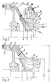
- FIG. 1 shows a fan arrangement which is frequently encountered in electrical machines and is similarly known from DE 32 07 448.
- a fan wheel 3 is arranged on a machine shaft 1 of a closed electrical machine 2.
- the fan wheel 3 has a support disk 4 for some fan blades 5.
- the fan blades 5 have a straight upper edge 6, which runs approximately parallel to the shaft 1, and a front edge 7 perpendicular thereto.
- the fan wheel 3 is covered by a fan hood 8 with a cylindrical wall part 9 and a vertical wall part 10 with a Air inlet 11, which is covered by a grid 12.
- a main air flow 13 and a parasitic return flow 14 are formed.
- the main air flow 13 is led via air outlets 15 to cooling fins (not shown) on the electrical machine 2.
- the parasitic backflow 14 constricts the main airflow 13 almost in the entire flow channel from the air inlet 11 to the air outlet 15 and thus causes considerable losses.
- FIG. 2 shows a first variant of a fan arrangement according to the invention, in which a strong main air flow 13 is formed and practically no parasitic backflow.
- a frustoconical wall part 16 which adjoins a first cylindrical wall part 17 which is adapted to the diameter D M of the electrical machine 2.
- the frustoconical wall part 16 is adapted to the air flow 13 which is not constricted. It should be pointed out that an optimal adaptation of the hood 8 to the course of the flow 13 is achieved if the angle of inclination ⁇ of the cone-shaped wall part 16 is smaller than the first cylindrical wall part 17 than the opening angle ⁇ of the support disk 4 with respect to the shaft 1. It can thus be achieved that the duct cross section for the air flow 13 remains approximately constant from the outlet from the fan wheel 3 to the air outlet 15.
- frustoconical wall part 16 measured about 25-40% of the upper edge length of the fan blades 5 from the support disk 4 and a little above the upper edge 6 of the Fan blades 5 would end and the remaining part of the fan wheel 3 would protrude from the machine without a cover.
- this is only permissible for a degree of protection without contact protection, for example with degree of protection IPO according to DIN IEC 34 Part 5 or VDE 0530, Part 5. Therefore, in the first embodiment, a closed second cylindrical wall part 18 is provided, which adjoins the conical wall part 16 and is covered at the end by a grid 12.
- the distance between the grid 12 and the impeller 13 is not critical and depends solely on the relevant safety regulations.
- the distance between the fan wheel 3 and the second cylindrical wall part 18 is also not critical with regard to the fan properties. It is therefore possible to provide a uniform hood 8 for machines of the same height with different number of poles, the hood being expediently optimized for the four-pole machine, the diameter D L of the fan wheel 3 being approximately half as large as the diameter D M of the electrical machine 2
- the fan wheel diameter D L for the two-pole machine is typically about 0.3 times the machine diameter D M.
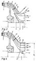
- FIG. 3 shows a second embodiment variant according to the invention, which is preferred because it leads to a further reduction in noise.
- the air can not only flow into the area of the fan wheel from the front side, but also from the side, but the air flow part flowing in from the side is not a parasitic backflow but part of the main flow.
- This second variant can be realized by a perforated design of the second cylindrical wall part 18 or by omitting the second cylindrical wall part and placing a hood-shaped grating 20 on the frustoconical wall part 16.
- the fan wheel 3 can, as shown in the drawing, be pushed onto the shaft, but can also be mounted on the end face of the shaft.
- the fan cover 8 can be made of steel, non-ferrous metals or plastic.
- FIG. 4 shows that the optimal hood shape according to FIG. 2 found for the use of a radial fan is also very well suited for the use of an axial fan wheel 21.
- the diameter D L of the axial fan wheel 21 is adapted to the diameter of the second cylindrical wall part 18 of the hood. Even with such an arrangement, essentially only one main air flow 13 is formed and parasitic backflow is prevented.
- the transition from the frustoconical wall part 16 to the second cylindrical wall part 18 lies approximately in the area of the air outlet 22 from the fan wheel 21.
Landscapes
- Engineering & Computer Science (AREA)
- Power Engineering (AREA)
- Structures Of Non-Positive Displacement Pumps (AREA)
- Motor Or Generator Cooling System (AREA)
Applications Claiming Priority (2)
| Application Number | Priority Date | Filing Date | Title |
|---|---|---|---|
| DE3720464 | 1987-06-20 | ||
| DE3720464A DE3720464C3 (de) | 1987-06-20 | 1987-06-20 | Lüfteranordnung für eine außenbelüftete elektrische Maschine |
Publications (3)
| Publication Number | Publication Date |
|---|---|
| EP0296447A2 EP0296447A2 (de) | 1988-12-28 |
| EP0296447A3 EP0296447A3 (en) | 1989-07-26 |
| EP0296447B1 true EP0296447B1 (de) | 1992-05-06 |
Family
ID=6329993
Family Applications (1)
| Application Number | Title | Priority Date | Filing Date |
|---|---|---|---|
| EP88109412A Expired - Lifetime EP0296447B1 (de) | 1987-06-20 | 1988-06-14 | Lüfteranordnung für eine aussenbelüftete elektrische Maschine |
Country Status (2)
| Country | Link |
|---|---|
| EP (1) | EP0296447B1 (enExample) |
| DE (2) | DE3720464C3 (enExample) |
Families Citing this family (3)
| Publication number | Priority date | Publication date | Assignee | Title |
|---|---|---|---|---|
| US6450765B1 (en) | 2000-06-19 | 2002-09-17 | Caterpillar Inc. | Sealing system for a centrifugal fan |
| JP5297236B2 (ja) * | 2009-03-17 | 2013-09-25 | 株式会社東芝 | 車両用全閉形主電動機 |
| DE102013100453B4 (de) | 2012-11-29 | 2024-08-22 | Vem Motors Gmbh | Innenkühlkreislaufsystem für rotierende elektrische Maschinen mit Kurzschlussläufer |
Family Cites Families (10)
| Publication number | Priority date | Publication date | Assignee | Title |
|---|---|---|---|---|
| DE7336007U (de) * | 1974-01-31 | Himmelwerk Ag | Geschlossener Elektromotor in schutzisolierter Ausführung | |
| DE1909065U (de) * | 1963-07-10 | 1965-01-28 | Siemens Schukkertwerke Ag | Elektrische maschine. |
| DE6810216U (de) * | 1968-12-02 | 1969-05-08 | Licentia Gmbh | Luefter fuer elektrische einbaumotoren |
| YU35939B (en) * | 1975-01-14 | 1981-08-31 | Oour Elektrotehnicki Inst Rade | Constructional arrangement for forced cooling of the inside air of closed rotational electric machines |
| CA1073511A (en) * | 1975-12-05 | 1980-03-11 | Westinghouse Electric Corporation | Quiet cooling system for dynamoelectric machines |
| DE2557620B2 (de) * | 1975-12-20 | 1978-08-03 | Felten & Guilleaume Carlswerk Ag, 5000 Koeln | Lüfter mit Lüfterhaube für eine oberflächenbelüftete, geschlossene elektrische Maschine |
| DE2649141C3 (de) | 1976-10-28 | 1979-10-18 | Institut Elektrosvarki Imeni E.O. Patona Akademii Nauk Ukrainskoj Ssr, Kiew (Sowjetunion) | Plasmalichtbogenofen zum Umschmelzen von Metallen und Legierungen |
| DE2649181A1 (de) * | 1976-10-28 | 1978-05-03 | Siemens Ag | Belueftungseinrichtung fuer elektrische maschinen |
| DE7813813U1 (de) * | 1978-05-08 | 1978-08-24 | Felten & Guilleaume Carlswerk Ag, 5000 Koeln | Doppelventilator als integrierter waermetauscher fuer einen elektromotor |
| DE3207448C2 (de) * | 1982-03-02 | 1985-11-07 | Siemens AG, 1000 Berlin und 8000 München | Lüfteranordnung für eine außenbelüftete elektrische Maschine |
-
1987
- 1987-06-20 DE DE3720464A patent/DE3720464C3/de not_active Expired - Fee Related
-
1988
- 1988-06-14 EP EP88109412A patent/EP0296447B1/de not_active Expired - Lifetime
- 1988-06-14 DE DE8888109412T patent/DE3870722D1/de not_active Expired - Lifetime
Non-Patent Citations (1)
| Title |
|---|
| Lueger, Lexikon der Energietechnik, Band 6, Seite 80 und Band 7, Seite 463 * |
Also Published As
| Publication number | Publication date |
|---|---|
| EP0296447A2 (de) | 1988-12-28 |
| DE3870722D1 (de) | 1992-06-11 |
| DE3720464C2 (enExample) | 1990-03-01 |
| EP0296447A3 (en) | 1989-07-26 |
| DE3720464A1 (de) | 1989-01-05 |
| DE3720464C3 (de) | 1993-09-30 |
Similar Documents
| Publication | Publication Date | Title |
|---|---|---|
| DE3428650C2 (de) | Haartrockner mit Axialgebläse | |
| EP3255281B1 (de) | Ventilator mit tandemnachleitschaufeln | |
| DE20214973U1 (de) | Gehäuse für ein Gebläse | |
| DE19753373A1 (de) | Axiallüfter-Gehäuse | |
| WO1995021330A1 (de) | Radialgebläserad | |
| DE4113394C3 (de) | Ringkanalgebläse | |
| DE10105570B4 (de) | Windkraftmaschine | |
| DE19549204C2 (de) | Elektrische Maschine, insbesondere Drehstromgenerator | |
| DE2743826B2 (de) | Elektromotor, der mit seinem abtriebsseitigen Ende an der Wand einer Arbeitsmaschine, insbesondere Geschirrspülmaschine, befestigt ist | |
| EP0296447B1 (de) | Lüfteranordnung für eine aussenbelüftete elektrische Maschine | |
| EP2888804B1 (de) | Elektrische maschine und verfahren zum kühlen einer elektrischen maschine | |
| DE10319270A1 (de) | Zentrifugalgebläse mit in einem Spiralgehäuse angeordnetem Zentrifugallüfter | |
| DE9415513U1 (de) | Windkraftanlage | |
| DE102019134354A1 (de) | Elektromotorvorrichtung mit einem Elektromotor und einer integralen Gebläsevorrichtung | |
| DE69606949T2 (de) | Mit verbesserter, interner Lüftungsvorrichtung versehene Lichtmaschine | |
| EP0364706A2 (de) | Pumpenaggregat, insbesondere für Geschirrspüler | |
| DE29717906U1 (de) | Gebläse | |
| DE9101715U1 (de) | Axiallüftereinheit | |
| DE3207448A1 (de) | Deckscheibenloser radialluefter | |
| DE3905092C2 (enExample) | ||
| DE3224517C2 (de) | Lüfterwalze für Querstromgebläse | |
| DE10111292A1 (de) | Lüfteranordnung für eine elektrische Maschine | |
| DE4335165B4 (de) | Radiallüfter | |
| DE9110195U1 (de) | Ventilator | |
| EP1369595B1 (de) | Leitrad für Ventilatoren, insbesondere von Luftkühlern |
Legal Events
| Date | Code | Title | Description |
|---|---|---|---|
| PUAI | Public reference made under article 153(3) epc to a published international application that has entered the european phase |
Free format text: ORIGINAL CODE: 0009012 |
|
| AK | Designated contracting states |
Kind code of ref document: A2 Designated state(s): CH DE FR GB LI NL |
|
| PUAL | Search report despatched |
Free format text: ORIGINAL CODE: 0009013 |
|
| AK | Designated contracting states |
Kind code of ref document: A3 Designated state(s): CH DE FR GB LI NL |
|
| 17P | Request for examination filed |
Effective date: 19890905 |
|
| 17Q | First examination report despatched |
Effective date: 19910517 |
|
| GRAA | (expected) grant |
Free format text: ORIGINAL CODE: 0009210 |
|
| AK | Designated contracting states |
Kind code of ref document: B1 Designated state(s): CH DE FR GB LI NL |
|
| ET | Fr: translation filed | ||
| REF | Corresponds to: |
Ref document number: 3870722 Country of ref document: DE Date of ref document: 19920611 |
|
| GBT | Gb: translation of ep patent filed (gb section 77(6)(a)/1977) | ||
| PLBI | Opposition filed |
Free format text: ORIGINAL CODE: 0009260 |
|
| 26 | Opposition filed |
Opponent name: SIEMENS AKTIENGESELLSCHAFT, BERLIN UND MUENCHEN Effective date: 19930129 |
|
| NLR1 | Nl: opposition has been filed with the epo |
Opponent name: SIEMENS AG. |
|
| PLBN | Opposition rejected |
Free format text: ORIGINAL CODE: 0009273 |
|
| STAA | Information on the status of an ep patent application or granted ep patent |
Free format text: STATUS: OPPOSITION REJECTED |
|
| 27O | Opposition rejected |
Effective date: 19950130 |
|
| NLR2 | Nl: decision of opposition | ||
| PGFP | Annual fee paid to national office [announced via postgrant information from national office to epo] |
Ref country code: NL Payment date: 19960410 Year of fee payment: 9 Ref country code: GB Payment date: 19960410 Year of fee payment: 9 |
|
| PGFP | Annual fee paid to national office [announced via postgrant information from national office to epo] |
Ref country code: FR Payment date: 19960412 Year of fee payment: 9 |
|
| PGFP | Annual fee paid to national office [announced via postgrant information from national office to epo] |
Ref country code: CH Payment date: 19960429 Year of fee payment: 9 |
|
| PGFP | Annual fee paid to national office [announced via postgrant information from national office to epo] |
Ref country code: DE Payment date: 19960507 Year of fee payment: 9 |
|
| PG25 | Lapsed in a contracting state [announced via postgrant information from national office to epo] |
Ref country code: GB Free format text: LAPSE BECAUSE OF NON-PAYMENT OF DUE FEES Effective date: 19970614 |
|
| PG25 | Lapsed in a contracting state [announced via postgrant information from national office to epo] |
Ref country code: LI Free format text: LAPSE BECAUSE OF NON-PAYMENT OF DUE FEES Effective date: 19970630 Ref country code: CH Free format text: LAPSE BECAUSE OF NON-PAYMENT OF DUE FEES Effective date: 19970630 |
|
| PG25 | Lapsed in a contracting state [announced via postgrant information from national office to epo] |
Ref country code: NL Effective date: 19980101 |
|
| GBPC | Gb: european patent ceased through non-payment of renewal fee |
Effective date: 19970614 |
|
| REG | Reference to a national code |
Ref country code: CH Ref legal event code: PL |
|
| PG25 | Lapsed in a contracting state [announced via postgrant information from national office to epo] |
Ref country code: FR Free format text: LAPSE BECAUSE OF NON-PAYMENT OF DUE FEES Effective date: 19980227 |
|
| NLV4 | Nl: lapsed or anulled due to non-payment of the annual fee |
Effective date: 19980101 |
|
| PG25 | Lapsed in a contracting state [announced via postgrant information from national office to epo] |
Ref country code: DE Free format text: LAPSE BECAUSE OF NON-PAYMENT OF DUE FEES Effective date: 19980303 |
|
| REG | Reference to a national code |
Ref country code: FR Ref legal event code: ST |
|
| REG | Reference to a national code |
Ref country code: FR Ref legal event code: ST |