EP0296447B1 - Fan arrangement for an outer ventilated electrical machine - Google Patents
Fan arrangement for an outer ventilated electrical machine Download PDFInfo
- Publication number
- EP0296447B1 EP0296447B1 EP88109412A EP88109412A EP0296447B1 EP 0296447 B1 EP0296447 B1 EP 0296447B1 EP 88109412 A EP88109412 A EP 88109412A EP 88109412 A EP88109412 A EP 88109412A EP 0296447 B1 EP0296447 B1 EP 0296447B1
- Authority
- EP
- European Patent Office
- Prior art keywords
- fan
- wall part
- cylindrical wall
- impeller
- approximately
- Prior art date
- Legal status (The legal status is an assumption and is not a legal conclusion. Google has not performed a legal analysis and makes no representation as to the accuracy of the status listed.)
- Expired - Lifetime
Links
Images
Classifications
-
- H—ELECTRICITY
- H02—GENERATION; CONVERSION OR DISTRIBUTION OF ELECTRIC POWER
- H02K—DYNAMO-ELECTRIC MACHINES
- H02K9/00—Arrangements for cooling or ventilating
- H02K9/14—Arrangements for cooling or ventilating wherein gaseous cooling medium circulates between the machine casing and a surrounding mantle
Definitions
- the invention relates to a fan arrangement according to the preamble of claim 1.
- FIG. 1 which in turn provides a large fan wheel, the fan blades of which are surrounded by a jacket-shaped guide element and connected to it.
- FIG. 1 provides a large fan wheel, the fan blades of which are surrounded by a jacket-shaped guide element and connected to it.
- DE-PS 32 07 448 it is pointed out that fan wheels without shrouds in accordance with CH 611 086 make it necessary to adapt the fan cover to machines with the same shaft height but a different number of poles. It is namely customary, with regard to the noise development, to design the fan wheels only as large as is necessary for a given number of poles and thus the speed with regard to a desired fan output.
- DE 32 07 448 proposes a fan cover with a cylindrical wall part and a straight end face oriented perpendicular to the shaft axis. The air inlet diameter must, however, be in a certain ratio to the fan wheel diameter.
- a strong parasitic backflow forms in the hood known from DE 32 07 448, which constricts the main flow through the fan wheel and thus reduces the fan output.
- the parasitic backflow worsens the efficiency and, above all, generates relatively high fan noise.
- DE-OS 26 49 141 proposes the use of a hood for an axial fan arrangement which is customary in radial fan arrangements. For this purpose, it is proposed either to provide the axial fan wheel with an air guide tube which also rotates as part of the fan wheel, or to provide an insert part in the hood which likewise guides the supply air. There is no suggestion for improving a radial fan arrangement in the document.
- DE-GBM 73 36 007 describes a radial fan arrangement with a large fan wheel and shown in the drawing.
- the associated fan cover has a frustoconical wall part, which is closed off by an air inlet grille arranged perpendicular to the motor shaft.
- the arrangement is low in backflow, but not low in noise. No suggestion for the design of the fan cover when using a fan wheel with a much smaller diameter can be found in the utility model.
- US Pat. No. 4,132,912 shows a fan arrangement with a radial fan wheel which has inclined end faces and at least 25 fan blades.
- the fan wheel is practically completely arranged within a frustoconical hood part which merges into a bell-shaped suction part.
- a certain air flow is to be enforced and parasitic backflow is prevented.
- the use of fan wheels of 40 to 60 blades is proposed as a low-noise design, but these are complex to manufacture.
- the invention has for its object to provide a fan assembly which leads to a further noise reduction and is still easy to manufacture and has only minor losses.
- the invention proposes a hood design that practically completely prevents parasitic backflow.
- the entire blade duct cross-section comes into effect, whereby the required fan power is achieved with a desirably small fan wheel.
- the fan noise is very low.
- a uniform fan hood can advantageously be used for machines of the same height.
- This uniform fan cover is appropriately optimized for a four-pole machine.
- the fan wheel for a two-pole machine is made smaller in diameter, which creates a larger gap between the second cylindrical wall part and the fan blades, but this has only a minor influence on the fan properties.
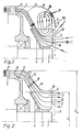
- FIG. 1 shows a fan arrangement which is frequently encountered in electrical machines and is similarly known from DE 32 07 448.
- a fan wheel 3 is arranged on a machine shaft 1 of a closed electrical machine 2.
- the fan wheel 3 has a support disk 4 for some fan blades 5.
- the fan blades 5 have a straight upper edge 6, which runs approximately parallel to the shaft 1, and a front edge 7 perpendicular thereto.
- the fan wheel 3 is covered by a fan hood 8 with a cylindrical wall part 9 and a vertical wall part 10 with a Air inlet 11, which is covered by a grid 12.
- a main air flow 13 and a parasitic return flow 14 are formed.
- the main air flow 13 is led via air outlets 15 to cooling fins (not shown) on the electrical machine 2.
- the parasitic backflow 14 constricts the main airflow 13 almost in the entire flow channel from the air inlet 11 to the air outlet 15 and thus causes considerable losses.
- FIG. 2 shows a first variant of a fan arrangement according to the invention, in which a strong main air flow 13 is formed and practically no parasitic backflow.
- a frustoconical wall part 16 which adjoins a first cylindrical wall part 17 which is adapted to the diameter D M of the electrical machine 2.
- the frustoconical wall part 16 is adapted to the air flow 13 which is not constricted. It should be pointed out that an optimal adaptation of the hood 8 to the course of the flow 13 is achieved if the angle of inclination ⁇ of the cone-shaped wall part 16 is smaller than the first cylindrical wall part 17 than the opening angle ⁇ of the support disk 4 with respect to the shaft 1. It can thus be achieved that the duct cross section for the air flow 13 remains approximately constant from the outlet from the fan wheel 3 to the air outlet 15.
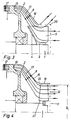
- frustoconical wall part 16 measured about 25-40% of the upper edge length of the fan blades 5 from the support disk 4 and a little above the upper edge 6 of the Fan blades 5 would end and the remaining part of the fan wheel 3 would protrude from the machine without a cover.
- this is only permissible for a degree of protection without contact protection, for example with degree of protection IPO according to DIN IEC 34 Part 5 or VDE 0530, Part 5. Therefore, in the first embodiment, a closed second cylindrical wall part 18 is provided, which adjoins the conical wall part 16 and is covered at the end by a grid 12.
- the distance between the grid 12 and the impeller 13 is not critical and depends solely on the relevant safety regulations.
- the distance between the fan wheel 3 and the second cylindrical wall part 18 is also not critical with regard to the fan properties. It is therefore possible to provide a uniform hood 8 for machines of the same height with different number of poles, the hood being expediently optimized for the four-pole machine, the diameter D L of the fan wheel 3 being approximately half as large as the diameter D M of the electrical machine 2
- the fan wheel diameter D L for the two-pole machine is typically about 0.3 times the machine diameter D M.
- FIG. 3 shows a second embodiment variant according to the invention, which is preferred because it leads to a further reduction in noise.
- the air can not only flow into the area of the fan wheel from the front side, but also from the side, but the air flow part flowing in from the side is not a parasitic backflow but part of the main flow.
- This second variant can be realized by a perforated design of the second cylindrical wall part 18 or by omitting the second cylindrical wall part and placing a hood-shaped grating 20 on the frustoconical wall part 16.
- the fan wheel 3 can, as shown in the drawing, be pushed onto the shaft, but can also be mounted on the end face of the shaft.
- the fan cover 8 can be made of steel, non-ferrous metals or plastic.
- FIG. 4 shows that the optimal hood shape according to FIG. 2 found for the use of a radial fan is also very well suited for the use of an axial fan wheel 21.
- the diameter D L of the axial fan wheel 21 is adapted to the diameter of the second cylindrical wall part 18 of the hood. Even with such an arrangement, essentially only one main air flow 13 is formed and parasitic backflow is prevented.
- the transition from the frustoconical wall part 16 to the second cylindrical wall part 18 lies approximately in the area of the air outlet 22 from the fan wheel 21.
Description
Die Erfindung bezieht sich auf eine Lüfteranordnung nach dem Oberbegriff des Anspruches 1.The invention relates to a fan arrangement according to the preamble of
Aus der CH-PS 611 086 ist eine Lüfteranordnung mit einem großen deckscheibenlosen Lüfterrad bekannt, wobei der Lüfterraddurchmesser nahezu an den Durchmesser der Lüfterhaube bzw. der gesamten elektrischen Maschine heranreicht (vergl. dort Figur 3). Die Lüfterflügel des dabei verwendeten Lüfterrades weisen eine gekrümmte Außenkante auf, wodurch eine Anpassung an die Haubenkontur gegeben ist. Der Luftspalt zwischen Lüfterrad und Haube muß möglichst klein sein, um die Geräuschentwicklung und Leistungsverluste aufgrund einer parasitären Rückströmung niedrig zu halten. In der CH-PS 611 086 wird dargelegt, daß diese bekannte Anordnung hohen Forderungen an die Laufruhe nicht gerecht werden kann. Um relativ kleine Lüfterräder verwenden zu können, ist aus der dortigen Figur 2 eine Lösung mit feststehendem Leitapparat bekannt, wobei jedoch darauf hingewiesen wird, daß trotz aufwendiger Fertigung keine befriedigende Lösung zu erreichen ist, weil eine relativ große parasitäre RückStrömung auftritt. Um diese Nebenströmung klein zu halten, wird eine dort in Figur 1 dargestellte Lösung vorgeschlagen, die wiederum ein großes Lüfterrad vorsieht, dessen Lüfterflügel von einem mantelförmigen Leitelement umgeben und mit diesem verbunden sind. Allerdings lassen sich auch mit dieser Anordnung erhöhte Anforderungen bezüglich Geräuschminderung nicht erfüllen.From CH-PS 611 086 a fan arrangement with a large cover plate-less fan wheel is known, the fan wheel diameter almost reaching the diameter of the fan cover or the entire electrical machine (see FIG. 3 there). The fan blades of the fan wheel used in this case have a curved outer edge, as a result of which there is an adaptation to the hood contour. The air gap between the fan wheel and hood must be as small as possible in order to keep noise and power losses due to a parasitic backflow low. In CH-PS 611 086 it is stated that this known arrangement cannot meet high demands on smooth running. In order to be able to use relatively small fan wheels, a solution with a fixed diffuser is known from FIG. 2 there, however, it is pointed out that, despite complex production, a satisfactory solution cannot be achieved because a relatively large parasitic backflow occurs. In order to keep this secondary flow small, a solution is shown in FIG. 1, which in turn provides a large fan wheel, the fan blades of which are surrounded by a jacket-shaped guide element and connected to it. However, even with this arrangement, increased requirements with regard to noise reduction cannot be met.
In der DE-PS 32 07 448 wird darauf hingewiesen, daß deckscheibenlose Lüfterräder entsprechend der CH 611 086 eine Anpassung der Lüfterhaube an Maschinen mit zwar gleicher Achshöhe aber unterschiedlicher Polzahl erforderlich machen. Es ist nämlich üblich, mit Rücksicht auf die Geräuschentwicklung die Lüfterräder nur so groß auszuführen, wie es bei einer gegebenen Polzahl und damit der Drehzahl im Hinblick auf eine gewünschte Lüfterleistung erforderlich ist. Um eine einheitliche Lüfterhaube für Achshöhen gleicher Maschinen unterschiedlicher Polzahl verwenden zu können, wird in der DE 32 07 448 eine Lüfterhaube mit einem zylinderförmigen Wandteil und einer geraden senkrecht zur Wellenachse ausgerichteten Stirnseite vorgeschlagen. Der Lufteinlaßdurchmesser muß allerdings in einem bestimmten Verhältnis zum Lüfterraddurchmesser stehen.In DE-PS 32 07 448 it is pointed out that fan wheels without shrouds in accordance with CH 611 086 make it necessary to adapt the fan cover to machines with the same shaft height but a different number of poles. It is namely customary, with regard to the noise development, to design the fan wheels only as large as is necessary for a given number of poles and thus the speed with regard to a desired fan output. In order to be able to use a uniform fan cover for shaft heights of the same machines with different numbers of poles, DE 32 07 448 proposes a fan cover with a cylindrical wall part and a straight end face oriented perpendicular to the shaft axis. The air inlet diameter must, however, be in a certain ratio to the fan wheel diameter.
In der aus der DE 32 07 448 bekannten Haube bildet sich eine kräftige parasitäre Rückströmung aus, die den Hauptstrom durch das Lüfterrad einschnürt und somit die Lüfterleistung verringert. Außerdem verschlechtert die parasitäre Rückströmung den Wirkungsgrad und vor allem entstehen relativ hohe Lüftergeräusche.A strong parasitic backflow forms in the hood known from DE 32 07 448, which constricts the main flow through the fan wheel and thus reduces the fan output. In addition, the parasitic backflow worsens the efficiency and, above all, generates relatively high fan noise.
Der DE-OS 26 49 141 sind Vorschläge zur Verwendung einer bei Radiallüfteranordnungen üblichen Haube für eine Axiallüfteranordnung zu entnehmen. Dazu wird vorgeschlagen, entweder das Axiallüfterrad mit einem Luftführungsrohr zu versehen, das als Teil des Lüfterrads mitrotiert, oder einen Einsatzteil in der Haube vorzusehen, der ebenfalls eine Führung der Zuluft bewirkt. Eine Anregung zur Verbesserung einer Radiallüfteranordnung ist der Druckschrift nicht zu entnehmen.DE-OS 26 49 141 proposes the use of a hood for an axial fan arrangement which is customary in radial fan arrangements. For this purpose, it is proposed either to provide the axial fan wheel with an air guide tube which also rotates as part of the fan wheel, or to provide an insert part in the hood which likewise guides the supply air. There is no suggestion for improving a radial fan arrangement in the document.
In dem DE-GBM 73 36 007 ist eine Radiallüfteranordnung mit einem großen Lüfterrad beschrieben und in der Zeichnung dargestellt. Die zugehörige Lüfterhaube weist einen kegelstumpfförmigen Wandteil auf, der durch ein senkrecht zur Motorwelle angeordnetes Lufteinlaßgitter abgeschlossen ist. Die Anordnung ist zwar rückströmungsarm, jedoch nicht geräuscharm. Eine Anregung zur Gestaltung der Lüfterhaube bei Verwendung eines Lüfterrades mit wesentlich kleinerem Durchmesser ist dem Gebrauchsmuster nicht zu entnehmen.DE-GBM 73 36 007 describes a radial fan arrangement with a large fan wheel and shown in the drawing. The associated fan cover has a frustoconical wall part, which is closed off by an air inlet grille arranged perpendicular to the motor shaft. The arrangement is low in backflow, but not low in noise. No suggestion for the design of the fan cover when using a fan wheel with a much smaller diameter can be found in the utility model.
Der US 4,132,912 ist eine Lüfteranordnung mit einem Radiallüfterrad zu entnehmen, das schräge Stirnflächen und mindestens 25 Lüfterschaufeln aufweist. Das Lüfterrad ist praktisch vollständig innerhalb eines kegelstumpfförmigen Haubenteils angeordnet, der in einen glockenförmigen Ansaugteil übergeht. Mit der bekannten Anordnung soll eine bestimmte Luftführung erzwungen und eine parasitäre Rückströmung unterbunden werden. Als geräuscharme Ausführung wird die Verwendung von Lüfterrädern von 40 bis 60 Schaufeln vorgeschlagen, die jedoch in der Herstellung aufwendig sind.US Pat. No. 4,132,912 shows a fan arrangement with a radial fan wheel which has inclined end faces and at least 25 fan blades. The fan wheel is practically completely arranged within a frustoconical hood part which merges into a bell-shaped suction part. With the known arrangement, a certain air flow is to be enforced and parasitic backflow is prevented. The use of fan wheels of 40 to 60 blades is proposed as a low-noise design, but these are complex to manufacture.
Der Erfindung liegt die Aufgabe zugrunde, eine Lüfteranordnung anzugeben, die zu einer weiteren Geräuschminderung führt und trotzdem einfach herzustellen ist und nur geringe Verluste aufweist.The invention has for its object to provide a fan assembly which leads to a further noise reduction and is still easy to manufacture and has only minor losses.
Diese Aufgabe wird gelöst durch eine Lüfteranordnung für eine außenbelüftete elektrische Maschine
- a) mit einem auf deren Welle außerhalb des Maschinengehäuses angeordneten deckscheibenlosen Radiallüfter, der aus einem Lüfterrad mit einer Tragscheibe und mehreren Lüfterschaufeln besteht,
- b) mit einer Lüfterhaube, die aufweist:
- mindestens einen ersten zylindrischen Wandteil, der mit seinem Außendurchmesser an die Maschinenkontur angepaßt ist, und
- außerdem einen kegelstumpfförmigen Wandteil, der sich mit seiner Öffnung mit dem größeren Durchmesser an den ersten zylindrischen Wandteil anschließt und
- einen Lufteinlaß, und
- c) bei der im Radiallüfter ein relativ kleines Lüfterrad eingesetzt ist, wobei die Lüftertragscheibe des Lüfterrades gegen die Welle einen Öffnungswinkel Alpha im Bereich von 45° und 90° aufweist, und der Neigungswinkel Beta des kegelstumpfförmigen Wandteils gegen die Richtung der Wellenachse jeweils kleiner ist als der gewählte Öffnungswinkel Alpha, wobei
- d) der kegelstumpfförmige Wandteil an den Strömungsverlauf in der Haube angepaßt ist und oberhalb der axial, etwa parallel zur Welle (1) verlaufenden Oberkante der Lüfterflügel, etwa an 25-40% der Länge dieser Oberkante - von der Lüftertragscheibe aus gemessen - endet, und
- e) das Lüfterrad etwa senkrecht zur Achse verlaufende Stirnkanten der Lüfterflügel aufweist, und das Verhältnis des Lüfterraddurchmessers zum Durchmesser des ersten zylindrischen Wandteils der Lüfterhaube bei achtpoligen Maschinen etwa 0,5 beträgt und bei zweipoligen Maschinen etwa 0,3.
- a) with a cover diskless radial fan arranged on its shaft outside the machine housing and consisting of a fan wheel with a support disk and several fan blades,
- b) with a fan cover, which has:
- at least a first cylindrical wall part which is adapted with its outer diameter to the machine contour, and
- also a frustoconical wall part, which connects with its opening with the larger diameter to the first cylindrical wall part and
- an air inlet, and
- c) in which a relatively small fan wheel is used in the radial fan, the fan support disk of the fan wheel against the shaft having an opening angle alpha in the range of 45 ° and 90 °, and the angle of inclination beta of the frustoconical wall part against the direction of the shaft axis is smaller than the selected opening angle alpha, where
- d) the frustoconical wall part is adapted to the flow in the hood and ends above the axially, approximately parallel to the shaft (1) upper edge of the fan blades, at about 25-40% of the length of this upper edge - measured from the fan support disk - and
- e) the fan wheel has end edges of the fan blades running approximately perpendicular to the axis, and the ratio of the fan wheel diameter to the diameter of the first cylindrical wall part of the fan cover is approximately 0.5 in eight-pole machines and approximately 0.3 in two-pole machines.
Vorteilhafte Ausgestaltungen sind in den Unteransprüchen angegeben und anhand von Ausführungsbeispielen beschrieben.Advantageous refinements are specified in the subclaims and described using exemplary embodiments.
Mit der Erfindung wird eine Haubengestaltung vorgeschlagen, die eine Entstehung einer parasitären Rückströmung praktisch ganz verhindert. Der gesamte Schaufelkanalquerschnitt kommt zur Wirkung, wodurch die benötigte Lüfterleistung mit einem wünschenswert kleinen Lüfterrad erreicht wird. Die Lüftergeräusche sind sehr gering. Bei der erfindungsgemäßen Lösung kann vorteilhaft für achshöhengleiche Maschinen eine einheitliches Lüfterhaube verwendet werden. Diese einheitliche Lüfterhaube wird zweckmäßig für eine vierpolige Maschine optimiert. Das Lüfterrad für eine zweipolige Maschine wird zwar im Durchmesser kleiner ausgeführt, wodurch ein größerer Spalt zwischen dem zweiten zylindrischen Wandteil und den Lüfterschaufeln entsteht, der jedoch nur einen geringen Einfluß auf die Lüftereigenschaften hat.The invention proposes a hood design that practically completely prevents parasitic backflow. The entire blade duct cross-section comes into effect, whereby the required fan power is achieved with a desirably small fan wheel. The fan noise is very low. In the solution according to the invention, a uniform fan hood can advantageously be used for machines of the same height. This uniform fan cover is appropriately optimized for a four-pole machine. The fan wheel for a two-pole machine is made smaller in diameter, which creates a larger gap between the second cylindrical wall part and the fan blades, but this has only a minor influence on the fan properties.
Die Erfindung wird anhand von in der Zeichnung dargestellten Ausführungsbeispielen näher erläutert.The invention is explained in more detail with reference to exemplary embodiments shown in the drawing.
Es zeigt:
- Fig. 1
- Eine Anordnung nach dem Stand der Technik,
- Fig. 2
- eine erste Variante einer erfindungsgemäßen Gestaltung einer Lüfterhaube,
- Fig. 3
- eine zweite Variante einer erfindungsgemäßen Gestaltung einer Lüfterhaube mit haubenförmigem Abdeckgitter für den Lufteinlaß,
- Fig. 4
- Zeigt den Einsatz eines Axiallüfters in einer erfindungsgemäßen Lüfterhaube.
- Fig. 1
- An arrangement according to the prior art,
- Fig. 2
- a first variant of a fan hood design according to the invention,
- Fig. 3
- a second variant of an inventive design of a fan hood with hood-shaped cover grille for the air inlet,
- Fig. 4
- Shows the use of an axial fan in a fan cover according to the invention.
Figur 1 zeigt eine bei realisierten elektrischen Maschinen häufig anzutreffende Lüfteranordnung, die in ähnlicher Ausführung auch aus der DE 32 07 448 bekannt ist. Auf einer Maschinenwelle 1 einer geschlossenen elektrischen Maschine 2 ist ein Lüfterrad 3 angeordnet. Das Lüfterrad 3 hat eine Tragscheibe 4 für einige Lüfterflügel 5. Die Lüfterflügel 5 weisen eine gerade, etwa parallel zur Welle 1 verlaufende Oberkante 6 und eine dazu senkrechte Stirnkante 7 auf. Das Lüfterrad 3 ist abgedeckt durch eine Lüfterhaube 8 mit einem zylindrischen Wandteil 9 und einem senkrechten Wandteil 10 mit einem Lufteinlaß 11, der durch ein Gitter 12 abgedeckt ist. In dieser Anordnung bildet sich eine Hauptluftstrom 13 und ein parasitärer Rückstrom 14 auf. Der Hauptluftstrom 13 wird über Luftauslässe 15 zu nicht dargestellten Kühlrippen an der elektrischen Maschine 2 geführt. Der parasitäre Rückstrom 14 schnürt den Hauptluftstrom 13 nahezu im gesamten Strömungskanal vom Lufteinlaß 11 bis zum Luftauslaß 15 eine und verursacht somit erhebliche Verluste.FIG. 1 shows a fan arrangement which is frequently encountered in electrical machines and is similarly known from DE 32 07 448. A
In der nachstehenden Beschreibung den übrigen Figuren sind übereinstimmende Teile in gleicher Weise bezeichnet.In the following description of the remaining figures, identical parts are identified in the same way.
Figur 2 zeigt eine erfindungsgemäße erste Variante einer Lüfteranordnung, bei der sich ein kräftiger Hauptlauftstrom 13 ausbildet und praktisch keine parasitäre Rückströmung. Dies wird erreicht durch einen kegelstumpfförmigen Wandteil 16, der sich an einen ersten zylindrischen Wandteil 17 anschließt, der an den Durchmesser DM der elektrischen Maschine 2 angepaßt ist. Der kegelstümpfförmige Wandteil 16 ist angepaßt an den nicht eingeschnürten Luftstrom 13. Es ist darauf hinzuweisen, daß eine optimale Anpassung der Haube 8 an den Verlauf der Strömung 13 erreicht wird, wenn der Neigungswinkel β des kegelstrumfförmigen Wandteils 16 gegenüber dem ersten zylindrischen Wandteil 17 kleiner ist als der Öffnungswinkel α der Tragscheibe 4 gegenüber der Welle 1. Damit kann erreicht werden, daß der Kanalquerschnitt für den Luftstrom 13 etwa konstant bleibt vom Austritt aus dem Lüfterrad 3 bis zum Luftauslaß 15.FIG. 2 shows a first variant of a fan arrangement according to the invention, in which a strong
Aus strömungstechnischen Gründen wäre es optimal, wenn der kegelstumpfartige Wandteil 16 etwa 25-40% der Oberkantenlänge der Lüfterflügel 5, von der Tragscheibe 4 aus gemessen und wenig oberhalb der Oberkante 6 der Lüfterflügel 5 enden würde und der restliche Teil des Lüfterrades 3 ohne Abdeckung aus der Maschine ragen würde. Dies ist jedoch nur bei einer Schutzart ohne Berührungsschutz, z.B. bei Schutzart IPO nach DIN IEC 34 Teil 5, bzw. VDE 0530, Teil 5 zulässig. Deshalb ist in der ersten Ausführungsvariante ein geschlossener zweiter zylinsdrischer Wandteil 18 vorgesehen, der sich an den kegelförmigen Wandteil 16 anschließt und stirnseitig durch ein Gitter 12 abgedeckt ist. Der Abstand zwischen dem Gitter 12 und dem Laufrad 13 ist unkritisch und richtet sich allein nach den einschlägigen Sicherheitsvorschriften. Auch der Abstand zwischen Lüfterrad 3 und zweitem zylindrischem Wandteil 18 ist nicht seht kritisch im Hinblick auf die Lüftereigenschaften. Deshalb ist es möglich, eine einheitliche Haube 8 für achshöhengleiche Maschinen unterschiedlicher Polzahl vorzusehen, wobei man die Haube zweckmäßig für die vierpolige Maschine optimiert, wobei der Durchmesser DL des Lüfterrads 3 etwa halb so groß ist, wie der Durchmesser DM der elektrischen Maschine 2. Der Lüfterraddurchmesser DL für die zweipolige Maschine ist typisch etwa 0,3-mal Maschinendurchmesser DM.For fluidic reasons, it would be optimal if the
Figur 3 zeigt eine zweite erfindungsgemäße Ausführungsvariante, die bevorzugt wird, weil sie zu einer weiteren Geräuschminderung führt. Dabei kann die Luft nicht nur von der Stirnseite, sondern auch von der Seite in den Bereich des Lüfterrades einströmen, wobei jedoch die von der Seite einströmenden Luftstromteil keine parasitäre Rückströmung, sondern Teil des Hauptstromes sind. Diese zweite Variante kann realisiert werden durch eine durchbrochene Ausführung des zweiten zylindrischen Wandteils 18 oder durch Weglassen des zweiten zylindrischen Wandteiles und Aufsetzen eines haubenförmigen Gitters 20 auf den kegelstumpfförmigen Wandteil 16.FIG. 3 shows a second embodiment variant according to the invention, which is preferred because it leads to a further reduction in noise. The air can not only flow into the area of the fan wheel from the front side, but also from the side, but the air flow part flowing in from the side is not a parasitic backflow but part of the main flow. This second variant can be realized by a perforated design of the second
Das Lüfterrad 3 kann, wie in der Zeichnung dargestellt, auf die Welle aufgeschoben sein, kann aber auch auf die Stirnseite der Welle montiert werden. Je nach Anforderung an Festigkeit, Herstellkosten, Magnetisierbarkeit, Gewicht sowie chemischer und thermischer Beständigkeit kann die Lüfterhaube 8 aus Stahl, Nichteisenmetallen oder Kunststoff gefertigt sein.The
Figur 4 zeigt, daß die für den Einsatz eines Radiallüfters gefundene optimale Haubenform gemäß Figur 2 auch sehr gut geeignet ist für den Einsatz eines Axiallüfterrades 21. Der Durchmesser DL des Axiallüfterrades 21 ist an den Durchmesser des zweiten zylindrischen Wandteils 18 der Haube angepaßt. Auch bei einer solchen Anordnung bildet sich im wesentlichen nur ein Hauptluftstrom 13 aus und eine parasitäre Rückströmung wird verhindert. Der Übergang des kegelstumpfförmigen Wandteils 16 zum zweiten zylindrischen Wandteil 18 liegt etwa im Bereich des Luftaustritts 22 aus dem Lüfterrad 21.FIG. 4 shows that the optimal hood shape according to FIG. 2 found for the use of a radial fan is also very well suited for the use of an
Claims (3)
- Fan arrangement for an externally ventilated electrical machinea) with, located on the shaft of the electrical machine and outside the machine casing, a shroudless radial fan which consists of an impeller with an impeller disc and a plurality of fan blades,b) with a fan cowl, which has:- at least one first cylindrical wall part whose external diameter is matched to the machine contour, and- in addition, a truncated cone shaped wall part whose larger diameter opening joins onto the first cylindrical wall part and- an air inlet, andc) in which fan arrangement a relatively small impeller is inserted in the radial fan, the impeller disc of the impeller having an included angle alpha relative to the shaft in the range between 45° and 90°, and the angle of inclination beta of the truncated cone shaped wall part (16) relative to the direction of the shaft axis being smaller in each case than the included angle alpha selected,
characterised in thatd) the truncated cone shaped wall part (16) is matched to the course of the flow in the cowl (8) and ends above the axial upper edge (6), extending approximately parallel to the shaft (1), of the fan blades (5) approximately at 25-40% of the length of this upper edge (6) - measured from the impeller disc (4) - ande) the impeller (3) has leading edges (7) of the fan blades (5) extending approximately at right angles to the centre line, and the ratio of the impeller diameter (DL) to the diameter (DM) of the first cylindrical wall part (9) of the fan cowl (8) is approximately 0.5 in the case of eight-pole machines and approximately 0.3 in the case of two-pole machines. - Fan arrangement according to Claim 1, characterised in that a second approximately cylindrical wall part (18) joins, by means of a closed cylindrical wall, onto the opening of the truncated cone shaped wall part (16) of the cowl (8), the closed cylindrical wall being closed at the air inlet side by means of a grid (12).
- Fan arrangement according to Claim 1, characterised in that a second approximately cylindrical wall part (18) joins onto the opening of the truncated cone shaped wall part (16) of the cowl (8), which second cylindrical wall part (18) has interruptions for an air inlet and is closed by means of a grid (12).
Applications Claiming Priority (2)
| Application Number | Priority Date | Filing Date | Title |
|---|---|---|---|
| DE3720464A DE3720464C3 (en) | 1987-06-20 | 1987-06-20 | Fan arrangement for an externally ventilated electrical machine |
| DE3720464 | 1987-06-20 |
Publications (3)
| Publication Number | Publication Date |
|---|---|
| EP0296447A2 EP0296447A2 (en) | 1988-12-28 |
| EP0296447A3 EP0296447A3 (en) | 1989-07-26 |
| EP0296447B1 true EP0296447B1 (en) | 1992-05-06 |
Family
ID=6329993
Family Applications (1)
| Application Number | Title | Priority Date | Filing Date |
|---|---|---|---|
| EP88109412A Expired - Lifetime EP0296447B1 (en) | 1987-06-20 | 1988-06-14 | Fan arrangement for an outer ventilated electrical machine |
Country Status (2)
| Country | Link |
|---|---|
| EP (1) | EP0296447B1 (en) |
| DE (2) | DE3720464C3 (en) |
Families Citing this family (3)
| Publication number | Priority date | Publication date | Assignee | Title |
|---|---|---|---|---|
| US6450765B1 (en) | 2000-06-19 | 2002-09-17 | Caterpillar Inc. | Sealing system for a centrifugal fan |
| JP5297236B2 (en) * | 2009-03-17 | 2013-09-25 | 株式会社東芝 | Fully closed main motor for vehicles |
| DE102013100453A1 (en) | 2012-11-29 | 2014-06-05 | Vem Motors Gmbh | Internal cooling circuit system for rotating type electric machine e.g. electric motor, has dual-fan that drives stator cooling channel flow, and twisting unit that is provided at short-circuit ring of rotor |
Family Cites Families (10)
| Publication number | Priority date | Publication date | Assignee | Title |
|---|---|---|---|---|
| DE7336007U (en) * | 1974-01-31 | Himmelwerk Ag | Closed electric motor with protective insulation | |
| DE1909065U (en) * | 1963-07-10 | 1965-01-28 | Siemens Schukkertwerke Ag | ELECTRIC MACHINE. |
| DE6810216U (en) * | 1968-12-02 | 1969-05-08 | Licentia Gmbh | FANS FOR ELECTRIC BUILT-IN MOTORS |
| YU35939B (en) * | 1975-01-14 | 1981-08-31 | Oour Elektrotehnicki Inst Rade | Constructional arrangement for forced cooling of the inside air of closed rotational electric machines |
| CA1073511A (en) * | 1975-12-05 | 1980-03-11 | Westinghouse Electric Corporation | Quiet cooling system for dynamoelectric machines |
| DE2557620B2 (en) * | 1975-12-20 | 1978-08-03 | Felten & Guilleaume Carlswerk Ag, 5000 Koeln | Fan with fan cover for a surface-ventilated, closed electrical machine |
| DE2649181A1 (en) * | 1976-10-28 | 1978-05-03 | Siemens Ag | Electric machine ventilating system with fan impeller - has radial fan cowl connected to machine and covering impeller |
| DE2649141C3 (en) | 1976-10-28 | 1979-10-18 | Institut Elektrosvarki Imeni E.O. Patona Akademii Nauk Ukrainskoj Ssr, Kiew (Sowjetunion) | Plasma arc furnace for remelting metals and alloys |
| DE7813813U1 (en) * | 1978-05-08 | 1978-08-24 | Felten & Guilleaume Carlswerk Ag, 5000 Koeln | DOUBLE FAN AS INTEGRATED HEAT EXCHANGER FOR AN ELECTRIC MOTOR |
| DE3207448C2 (en) * | 1982-03-02 | 1985-11-07 | Siemens AG, 1000 Berlin und 8000 München | Fan arrangement for an externally ventilated electrical machine |
-
1987
- 1987-06-20 DE DE3720464A patent/DE3720464C3/en not_active Expired - Fee Related
-
1988
- 1988-06-14 EP EP88109412A patent/EP0296447B1/en not_active Expired - Lifetime
- 1988-06-14 DE DE8888109412T patent/DE3870722D1/en not_active Expired - Fee Related
Non-Patent Citations (1)
| Title |
|---|
| Lueger, Lexikon der Energietechnik, Band 6, Seite 80 und Band 7, Seite 463 * |
Also Published As
| Publication number | Publication date |
|---|---|
| DE3720464A1 (en) | 1989-01-05 |
| EP0296447A2 (en) | 1988-12-28 |
| DE3870722D1 (en) | 1992-06-11 |
| DE3720464C2 (en) | 1990-03-01 |
| DE3720464C3 (en) | 1993-09-30 |
| EP0296447A3 (en) | 1989-07-26 |
Similar Documents
| Publication | Publication Date | Title |
|---|---|---|
| DE3428650C2 (en) | Hair dryer with axial fan | |
| DE2648850C3 (en) | Blade gap seal for axial fans | |
| EP3255281B1 (en) | Ventilator with tandem diffuser blades | |
| DE3128625C2 (en) | Side channel blower | |
| DE19753373A1 (en) | Housing for axial cooling fan for EMC-screened apparatus, such as CPU | |
| DE3017226A1 (en) | FAN BLADE | |
| EP0446316B2 (en) | Miniature fan | |
| EP0692076A1 (en) | Radial impeller | |
| DE4113394C3 (en) | Ring duct blower | |
| DE10105570B4 (en) | Wind power machine | |
| DE19549204C2 (en) | Electrical machine, in particular three-phase generator | |
| EP0296447B1 (en) | Fan arrangement for an outer ventilated electrical machine | |
| DE2743826B2 (en) | Electric motor, which is attached with its output-side end to the wall of a machine, in particular a dishwasher | |
| EP1081388B1 (en) | Fan | |
| DE10319270A1 (en) | Centrifugal blower with a centrifugal fan arranged in a spiral housing | |
| EP2888804B1 (en) | Electric machine and method for cooling an electric machine | |
| DE102017215261A1 (en) | FAN FOR AN ELECTRIC EQUIPMENT | |
| DE19709193B4 (en) | centrifugal fan | |
| DE102019134354A1 (en) | Electric motor device with an electric motor and an integral fan device | |
| DE3207448A1 (en) | Radial fan without a cover disc | |
| EP0499166A1 (en) | Axial fan unit | |
| EP3683451A1 (en) | Flow guide device and fan arrangement with a flow guide device | |
| DE3224517C2 (en) | Fan roller for cross-flow fan | |
| EP0364706A2 (en) | Pump unit, especially for dish washing machines | |
| DE3905092C2 (en) |
Legal Events
| Date | Code | Title | Description |
|---|---|---|---|
| PUAI | Public reference made under article 153(3) epc to a published international application that has entered the european phase |
Free format text: ORIGINAL CODE: 0009012 |
|
| AK | Designated contracting states |
Kind code of ref document: A2 Designated state(s): CH DE FR GB LI NL |
|
| PUAL | Search report despatched |
Free format text: ORIGINAL CODE: 0009013 |
|
| AK | Designated contracting states |
Kind code of ref document: A3 Designated state(s): CH DE FR GB LI NL |
|
| 17P | Request for examination filed |
Effective date: 19890905 |
|
| 17Q | First examination report despatched |
Effective date: 19910517 |
|
| GRAA | (expected) grant |
Free format text: ORIGINAL CODE: 0009210 |
|
| AK | Designated contracting states |
Kind code of ref document: B1 Designated state(s): CH DE FR GB LI NL |
|
| ET | Fr: translation filed | ||
| REF | Corresponds to: |
Ref document number: 3870722 Country of ref document: DE Date of ref document: 19920611 |
|
| GBT | Gb: translation of ep patent filed (gb section 77(6)(a)/1977) | ||
| PLBI | Opposition filed |
Free format text: ORIGINAL CODE: 0009260 |
|
| 26 | Opposition filed |
Opponent name: SIEMENS AKTIENGESELLSCHAFT, BERLIN UND MUENCHEN Effective date: 19930129 |
|
| NLR1 | Nl: opposition has been filed with the epo |
Opponent name: SIEMENS AG. |
|
| PLBN | Opposition rejected |
Free format text: ORIGINAL CODE: 0009273 |
|
| STAA | Information on the status of an ep patent application or granted ep patent |
Free format text: STATUS: OPPOSITION REJECTED |
|
| 27O | Opposition rejected |
Effective date: 19950130 |
|
| NLR2 | Nl: decision of opposition | ||
| PGFP | Annual fee paid to national office [announced via postgrant information from national office to epo] |
Ref country code: NL Payment date: 19960410 Year of fee payment: 9 Ref country code: GB Payment date: 19960410 Year of fee payment: 9 |
|
| PGFP | Annual fee paid to national office [announced via postgrant information from national office to epo] |
Ref country code: FR Payment date: 19960412 Year of fee payment: 9 |
|
| PGFP | Annual fee paid to national office [announced via postgrant information from national office to epo] |
Ref country code: CH Payment date: 19960429 Year of fee payment: 9 |
|
| PGFP | Annual fee paid to national office [announced via postgrant information from national office to epo] |
Ref country code: DE Payment date: 19960507 Year of fee payment: 9 |
|
| PG25 | Lapsed in a contracting state [announced via postgrant information from national office to epo] |
Ref country code: GB Free format text: LAPSE BECAUSE OF NON-PAYMENT OF DUE FEES Effective date: 19970614 |
|
| PG25 | Lapsed in a contracting state [announced via postgrant information from national office to epo] |
Ref country code: LI Free format text: LAPSE BECAUSE OF NON-PAYMENT OF DUE FEES Effective date: 19970630 Ref country code: CH Free format text: LAPSE BECAUSE OF NON-PAYMENT OF DUE FEES Effective date: 19970630 |
|
| PG25 | Lapsed in a contracting state [announced via postgrant information from national office to epo] |
Ref country code: NL Effective date: 19980101 |
|
| GBPC | Gb: european patent ceased through non-payment of renewal fee |
Effective date: 19970614 |
|
| REG | Reference to a national code |
Ref country code: CH Ref legal event code: PL |
|
| PG25 | Lapsed in a contracting state [announced via postgrant information from national office to epo] |
Ref country code: FR Free format text: LAPSE BECAUSE OF NON-PAYMENT OF DUE FEES Effective date: 19980227 |
|
| NLV4 | Nl: lapsed or anulled due to non-payment of the annual fee |
Effective date: 19980101 |
|
| PG25 | Lapsed in a contracting state [announced via postgrant information from national office to epo] |
Ref country code: DE Free format text: LAPSE BECAUSE OF NON-PAYMENT OF DUE FEES Effective date: 19980303 |
|
| REG | Reference to a national code |
Ref country code: FR Ref legal event code: ST |
|
| REG | Reference to a national code |
Ref country code: FR Ref legal event code: ST |