EP0295153A1 - Faserverstärkter Zementdachziegel und Verfahren zu dessen Herstellung - Google Patents
Faserverstärkter Zementdachziegel und Verfahren zu dessen Herstellung Download PDFInfo
- Publication number
- EP0295153A1 EP0295153A1 EP88305401A EP88305401A EP0295153A1 EP 0295153 A1 EP0295153 A1 EP 0295153A1 EP 88305401 A EP88305401 A EP 88305401A EP 88305401 A EP88305401 A EP 88305401A EP 0295153 A1 EP0295153 A1 EP 0295153A1
- Authority
- EP
- European Patent Office
- Prior art keywords
- weight
- tile
- parts
- fibers
- cement
- Prior art date
- Legal status (The legal status is an assumption and is not a legal conclusion. Google has not performed a legal analysis and makes no representation as to the accuracy of the status listed.)
- Granted
Links
Images


Classifications
-
- B—PERFORMING OPERATIONS; TRANSPORTING
- B28—WORKING CEMENT, CLAY, OR STONE
- B28B—SHAPING CLAY OR OTHER CERAMIC COMPOSITIONS; SHAPING SLAG; SHAPING MIXTURES CONTAINING CEMENTITIOUS MATERIAL, e.g. PLASTER
- B28B1/00—Producing shaped prefabricated articles from the material
- B28B1/52—Producing shaped prefabricated articles from the material specially adapted for producing articles from mixtures containing fibres, e.g. asbestos cement
-
- B—PERFORMING OPERATIONS; TRANSPORTING
- B28—WORKING CEMENT, CLAY, OR STONE
- B28B—SHAPING CLAY OR OTHER CERAMIC COMPOSITIONS; SHAPING SLAG; SHAPING MIXTURES CONTAINING CEMENTITIOUS MATERIAL, e.g. PLASTER
- B28B3/00—Producing shaped articles from the material by using presses; Presses specially adapted therefor
-
- E—FIXED CONSTRUCTIONS
- E04—BUILDING
- E04D—ROOF COVERINGS; SKY-LIGHTS; GUTTERS; ROOF-WORKING TOOLS
- E04D3/00—Roof covering by making use of flat or curved slabs or stiff sheets
- E04D3/24—Roof covering by making use of flat or curved slabs or stiff sheets with special cross-section, e.g. with corrugations on both sides, with ribs, flanges, or the like
- E04D3/26—Roof covering by making use of flat or curved slabs or stiff sheets with special cross-section, e.g. with corrugations on both sides, with ribs, flanges, or the like of concrete or ceramics
Definitions
- This invention relates to a tile that is made of cement and reinforced with fibers, for which the reinforcing material is made of synthetic fibers.
- Tiles generally have as their main ingredients clay and cement, and are installed one after another along the slope of a roof from the eaves to the ridge. At that time, the edge toward the ridge of a tile that is placed at the edge of the eaves has placed on the edge toward the eaves of the next tile. Each tile is supported by the attachment of the edge of the tile toward the ridge to the underlying building material such as flat boards, roofing, or the like, and by the placement of the edge of the tile toward the eaves on the top of the edge toward the ridge of the next tile.
- each tile toward the eaves is placed in a higher position with respect to the building material under the tiles than the edge of that tile toward the ridge, resulting in a space between the underneath surface of the tile and said building materials under the tiles. For that reason, when a load is placed on the central part of tiles installed in such a way on a roof, bending stress affects this central part, and gives rise to the danger of breakage of the tiles.
- the entire body of the tile can be made thick.
- the weight of the tile itself increases, which makes the tile costly.
- the work load at the time of the installation of the tiles on the roof is increased, and there is an additional disadvantage that the durability of the building itself is decreased.
- asbestos fibers have been mixed in as a reinforcing material.
- a mixture made of cement, asbestos, pulp, and the like in water is used to make a form in a cement mold like the process of making hand-made paper, and this is formed with pressure in a liquid roller, etc., in a so-called paper-making process, by which the hills and valleys are formed with approximately the same thickness.
- inorganic fibers such as glass fibers, inorganic fibers such as potassium titanate fibers, etc., organic fibers such as vinylon, acrylonitrile, polypropylene, polyamide, etc., or metallic fibers such as steel fibers, etc.
- tiles made of a cement in which short fibers of polyester, glass, etc., as reinforcing materials are disclosed in Japanese Patent Publication No. 57-9009.
- the tiles are light-weight, so their production is made easier, and another advantage is the high strength conferred.
- the hardness is slightly decreased, and as mentioned above, when the tiles are installed on a roof and there is a load placed on the central part of the tiles, the tiles are largely deformed, and stress accumulates in the center part of the tiles, bringing about the possibility that the tiles will break.
- tiles with this kind of shape are generally made with the hills and valleys of approximately the same thickness, so that when a large load is placed on the valleys, there is the disadvantage of the valleys being easily broken.
- Japanese Laid-Open Patent Application 58-213666 discloses a molding method that gives tiles made of cement and reinforced with fibers, wherein an inorganic filler and synthetic fibers are mixed with cement and 15-30 parts by weight of water per 100 parts by weight of the cement are added and kneaded by a kneader in which the surfaces of the fibers scratched, after which the amount of water needed for the formation of the particular shape is added, and molding is accomplished by, for example, the use of a press. Kneaders that have sharp protuberances in the kneading chamber, pressure kneaders, pulpers, or the like can be used.
- the synthetic fibers may come to be twisted around each other, and there is the chance of their forming a fiber ball.
- the chance of synthetic fibers becoming twisted around each other is greater than for asbestos fibers.
- the tile made of cement reinforced with fibers of this invention which overcomes the above-discussed and numerous other disadvantages and deficiencies of the prior art, has, per 100 parts by weight of cement, 0.3-7 parts by weight of synthetic fibers as reinforcing materials, and 200 parts by weight or less of an inorganic filler, wherein said tile has a wave-shape with alternating hills and valleys, which run in the direction of the slope of the roof when it is installed on the building material of the roof that is under the tiles of a sloping roof, the valley of the tile being 5-30% thicker than the hill, and/or the undersurface, except for the edges of the hills and valleys, being provided with a supporting stand.
- the supporting stand when the tile is installed on the building material of the roof that is under the tile, has a length y along the direction of the slope of the said building material under the tile, a length x at right angles to the said direction of the slope, and a maximum height h wherein y ⁇ 3 mm, x ⁇ 3 mm, and h ⁇ 60 mm.
- the method for the manufacture of tiles made of cement reinforced with fibers of this invention comprises the mixing of 200 parts by weight of an inorganic filler with an aqueous solution that has been or is being prepared by the dissolving of 1 part by weight or less of a water-soluble high polymer, if needed, into 30 parts by weight or more of water, the mixing by agitation of the mixture with 0.3-7 parts by weight of synthetic fibers, the mixing by agitation of the mixture with 100 parts by weight of cement, the putting of the mixture into a mold that can be opened and closed, and then the molding of the mixture at a rate of pressure of 0.3 mm/sec or more, resulting in the desired tile reinforced with fibers.
- the method of this invention comprises the mixing of 200 parts by weight of an inorganic filler and some of 100 parts by weight of cement with an aqueous solution that has been or is being prepared by the dissolving of 1 part by weight or less of a water-soluble high polymer, if needed, into 30 parts by weight or more of water, the mixing by agitation of the mixture with 0.3-7 parts by weight of synthetic fibers, the mixing by agitation of the mixture with the remaining cement, the putting of the mixture into a mold that can be opened and closed, and then the molding of the mixture at a rate of pressure of 0.3 mm/sec or more, resulting in a desired tile reinforced with fibers wherein said tile is in the shape of a wave with alternating hills and valleys, which run in the direction of the slope of the roof when the tile is installed on the building material of the roof that is under the tiles of a sloping roof, the valley of the tile being 5-30% thicker than the hill, and/or the undersurface, except for the edges of the hills and
- the method of this invention comprises the mixing of some of 200 parts by weight of an inorganic filler and some of 100 parts by weight of cement with an aqueous solution that has been or is being prepared by the dissolving of 1 part by weight or less of a water-soluble high polymer, if needed, into 30 parts by weight or more of water, the mixing by agitation of the mixture with 0.3-7 parts by weight of synthetic fibers, the mixing by agitation of the mixture with the remaining inorganic filler and the remaining cement, the putting of the mixture into a mold that can be opened and closed, and then the molding of the mixture at a rate of pressure of 0.3 mm/sec or more, resulting in the desired tile reinforced with fibers, wherein said tile is in the shape of a wave with alternating hills and valleys, which run in the direction of the slope of the roof when it is installed or the building material of the roof that is under the tiles of a sloping roof, the valley of the tile being 5-30% thicker than the hill, and/or the undersurface
- the method of this invention comprises the mixing of 200 parts by weight of an inorganic filler and some of 100 parts by weight of cement with an aqueous solution that has been or is being prepared by the dissolving of 1 part by weight or less of a water-soluble high polymer, if needed, into 30 parts by weight or more of water, the mixing by agitation of the mixture with some of 0.3-7 parts by weight of synthetic fibers, the mixing by agitation of the mixture with the remaining synthetic fibers and 100 parts by weight of cement, the putting of the mixture into a mold that can be opened and closed, and then the molding of the mixture at a rate of pressure of 0.3 mm/sec or more, resulting in the desired tile reinforced with fibers, wherein said tile is in the shape of a wave with alternating hills and valleys, which run in the direction of the slope of the roof when it is installed or the building material of the roof that is under the tiles of a sloping roof, the valley of the tile being 5-30% thicker than the hill, and/or the under
- the invention described herein makes possible the objectives of (1) providing light-weight tiles with improved strength by which the tiles are not readily broken even when a weight is put thereon; and a method for the manufacture of tiles made of cement reinforced with fibers by which synthetic fibers that function as a reinforcing material are not damaged and cut, and accordingly are uniformly dispersed into the cement matrix.
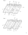
- Figure 1 shows a tile of this invention made of cement reinforced with fibers.
- the tile 1 is made from cement reinforced with fibers in which there are mixed, per 100 parts by weight of cement, 0.3-7 parts by weight of synthetic fibers as a reinforcing material, and 200 parts by weight or less of an inorganic filler, which mixture is stretched out to form a shape with alternating hills 2 and valleys 3 .
- Each hill 2 and valley 3 is semicircular in cross-section; the thickness of the valleys, m , is 5-30% more than the thickness l of the hills 3 . Also, the percentage of curve of the upper and lower surfaces of each valley 3 is approximately the same.
- This kind of tile 1 is put on the top of the building material under the tiles provided on the roof, and the tiles are placed so that the hills 2 and the valleys 3 of the tile run in the direction of the slope of the said roof.
- the tiles 1 are placed one after another from the bottom, the eaves side, to the top, the ridge side of the roof.
- the top of the ridge-side edge of a tile placed at the edge of the eaves has placed on the eaves-side edge of another tile. Because the valley parts of the tiles that are placed on the top of each other fit together as described above, the leakage of rainwater and the like under the tiles is prevented.
- the thickness m of the valleys 3 is 5-30% more than the thickness l of the hills 2 . If the thickness m of the valleys 3 is more than 30% more than the thickness l of the hills 2 , the strength against breakage of the hills declines markedly compared to the strength against breakage of the valleys 2 ; also, if the thickness m of the valleys 3 is less than 5% more than the thickness l of the hills 2 , the strength against breakage of the valleys 3 is not sufficient.
- cements that can be used for the tiles of this invention Portland cement, alumina cement, blast furnace cement, and other hydraulic cements can be used.
- synthetic fibers there are vinylon, polyamide, polyester, polypropylene, and other fibers, the thickness of which can be 2-40 deniers, and the length of which can be 2-30 mm.
- the amount of synthetic fibers to be added is 0.3-7 parts by weight. If the amount of synthetic fibers added is too small, the effect of reinforcement will not appear, and if the amount of synthetic fibers added is too large, the distribution of the said fibers will become poor, which decreases the flow during the time of molding, so that the effect of reinforcement by the said fibers will not appear.
- vinylon fibers are especially suitable because their flow characteristics are good, giving good formability.
- silica As inorganic filler, silica, river sand, fly ash, silica flour, bentonite, sepiolite, wollastonite, calcium carbonate, mica, and so on can be listed.
- a water-soluble polymer is used, if necessary.
- the inorganic filler and synthetic fibers can be distributed in the cement satisfactorily by themselves, the addition of the said water-soluble polymer is not necessarily required.
- water-soluble polymer methyl cellulose, carboxymethylcellulose, polyvinyl alcohol, hydroxyethylcellulose, polyacrylic acid, etc.
- the said water-soluble polymers act to disperse aggregates and synthetic fibers such as vinylon fibers and the like uniformly throughout the cement, and can be added to prevent the formation of fiber balls made by the precipitation of aggregates or by the mutual twisting together of the said fibers, for which purpose 1 part by weight or less can be added.
- the method of mixture by agitation can be used.
- agitation blades are not used, but instead, agitation involves the use of an apparatus to which is attached a vessel made of rubber that is pliable and is in the form of a disc-shaped agitating platform; the direction of the inclination of the agitating platform and the angle of the inclination can be continuously changed, so that the rubber vessel in which the materials to be mixed are placed is deformed and agitated, mixing them.
- the Omuni mixer of the Chiyoda Giken Kogyo Co. can be used as the apparatus for mixture by agitation.
- the tile of this invention is made from, for example, 100 parts by weight of cement, 30 parts by weight of fly ash, 2 parts by weight of vinylon fibers as the synthetic fibers, and 40 parts by weight of water, which are mixed to produce a cement composition that is reinforced with fiber, and the desired shape is formed by the use of a water-removing press on the said fiber-reinforced cement composition, after which the resulting molded product is heated at 60°C and at the relative humidity of 95% in a steam room for 24 hours for steam curing.
- the load resisted at the time of breakage of the tile 1 of this experiment was 240 kg.
- a reference tile was made in the same way as in the method of this invention, except that the thickness of the hills and valleys was a uniform 6 mm, and a test of resistance to loading was done.
- the load resisted at the time of breakage of the reference tile was 180 kg.
- a tile was made in the same way as in the method of this invention, except that the thickness of the hills and the valleys was a uniform 7 mm, and a test of resistance to leading was done.
- the load that was resisted at the time of breakage of the second reference tile was 240 kg, the same as the value found for the tile of this invention.
- the tile had the same resistance to a load as a tile that had hills with the same thickness as the thickness of the valleys on our tile.
- the tile cf this invention is economical, and because the tile is relatively light-weight, the operation of installing the tile on a roof is eased.
- FIG 4 shows another tile of this invention.
- This tile 10 also is formed in a wave shape so that when it is installed on a roof, there are alternate hills 14 and valleys 15 that follow the direction of the slope of the roof; in cross-section, the shape of each hill 14 and each valley 15 is a rectangle.
- the eaves-side edge 12 of the tile 10 is placed on the ridge-side edge of the next tile 10 .
- the said tile 10 has at its edge that is placed on the eaves side at the time of installation on the roof a downward-projecting part 13 that projects downward (in Figure 4 , it is shown projecting upward), which is provided continuously along each hill 14 and each valley 15 .
- a downward-projecting part 13 that projects downward (in Figure 4 , it is shown projecting upward), which is provided continuously along each hill 14 and each valley 15 .
- the groove 16 is provided continuously along each hill 14 and each valley 15 .
- the upward-projecting part 17 is provided continuously along each hill 14 and each valley 15 , and is fitted with the groove 16 mentioned above along the edge of the tile toward the eaves.
- the groove 18 is provided continuously along each hill 14 and each valley 15 , and the projection 13 that is established along the eaves side, as mentioned above, fits into the said groove 18 .
- each valley 15 there are a pair of supporting stands 20 and 21 that project downward.
- the supporting stands 20 and 21 are both in the shape of a right-angled parallelepiped, and one of the supporting stands, 20 , is placed near the edge of the tile toward the eaves, and the other supporting stand, 21 , is placed near the edge of the tile toward the ridge.
- the position of the supporting stands 20 and 21 at the time of roofing, corresponds to the main roof crosspiece that is under the building materials 19 of the roof that are under the tiles.
- each of the supporting stands 20 and 21 is set so that the supporting stands 20 and 21 can touch or can have a space from the building materials 19 when the tiles 10 are installed on the top of the building materials 19 under the tiles on a roof, whereby the ridge-side edge of the tile 10 comes into contact with the building material 19 ; the projection 13 on the eaves-side edge of the tile fits into the groove 18 on the ridge-side edge of the next tile that is placed toward the eaves; and moreover, the projection 17 on the ridge-side edge of the tile is fit into the groove 16 on the eaves-side edge of the next tile.
- the lower surfaces of the supporting stands 20 and 21 have the same slope as the building materials 19 placed under the tile 10 .
- the height of the supporting stand 20 on the eaves side of the tile is greater than the height of the supporting stand 21 on the ridge side.
- the bottom surfaces of said supporting stand 20 and 21 even when they are not directly connected with the building materials 19 under the tiles, come into direct contact with the building materials 19 under the tiles if a load is placed on the upper surface of the tile 10 and the tile 10 is deformed by the load.
- the tile of this kind of shape is also manufactured from a cement reinforced by fibers in which there are, per 100 parts of cement by weight, 0.3-7 parts by weight of synthetic fibers as reinforcing material, and 200 parts by weight or less of an inorganic filler.
- the supporting stands 20 and 21 are formed of the same material as the valleys and are made in one piece with the said valleys.
- the supporting stands 20 and 21 for the tiles 10 undergo the same compressive stress as the ridge-side edge of a tile 10 when the ridge-side edge of the tile 10 installed at the ridge side is placed on the eaves-side edge of the next tile 10 .
- cement that is reinforced with fibers has excellent strength against compression, but because the deformation of the tile 10 itself when a load is put on the said tile 10 must be minimized, the measurement y of the direction of the slope of the roof of the supporting stands 20 and 21 should be 3 mm or more, and the measurement x at right angles to that direction should be 3 mm or more, with the maximum height h being preferably 60 mm or less.
- both the measurement y of the supporting stands 20 and 21 in the direction of the roof slope and the measurement x in the direction at right angles to that direction are smaller than 3 mm, then when the tile 10 is produced from a cement composition reinforced with fibers by use of press molding, not every part of the mold for the molding of the supporting stands 20 and 21 is filled satisfactorily with the composition, and gaps in the supporting stands 20 and 21 to be molded may occur. Sufficient resistance to loading cannot be obtained with the supporting stands that have these kinds of gaps. If the maximum height h of the supporting stands 20 and 21 exceeds 60 mm, in the same way, not every part of the mold for the molding of the supporting stands is filled satisfactorily with the composition, and sufficient resistance to loading may not be obtained.
- the cement composition reinforced with fibers can fill every part of the mold for the molding of the supporting stands, and the deformation of the supporting stands 20 and 21 in response to the loading of the tile 10 can be minimized.
- the measurement of the maximum height h of the supporting stands 20 and 21 is 2 mm or less, the deformation in response to a load on the tile 10 is large, which is not desirable.
- the shapes of the supporting stands 20 and 21 are not limited to right-angled parallelepipeds; as shown in Figure 6 , they can be elliptical columns. In this case as well, it is preferable that the supporting stands 20 and 2 fulfill the conditions for measurements described above.
- the space between the undersurface of the valleys 15 and the building materials under the tile is smaller than the space between the undersurface of the hills 14 and the building materials under the tile, by the provision of a supporting stand on the undersurface of the said valley 15 , it is possible to make the measurements of the supporting stand small, so that the increase in the weight of the entire tile becomes small and economical.
- the thickness of the valleys is made 5-30% thicker than the thickness of the hills, the strength of the tile is yet more increased, and if the upper surface of the tile is stepped on by a person, there is no danger of breakage.
- each valley was provided on its underside with a pair of supporting stands 20 and 21 of elliptical shape, giving a tile 10 made of cement reinforced with fibers.
- the supporting stand 20 that was provided on the eaves-side ridge of the tile had a measurement y in the direction of the slope of the roof of 15 mm, a measurement x in the direction at right angles to that direction of 10 mm, and a measurement h for the maximum height of 15 mm; for the supporting stand 21 on the ridge-side edge, these measurements were 10 mm, 8 mm, and 7 mm, respectively.
- Some of the tiles 10 made of cement reinforced with fibers that were formed in Section 2 above were cured by being placed in water for 14 days. Then they were installed on a roof, and a person bearing a weight walked on the tiles. The weight required for the tiles to break when stepped on by a person bearing a weight was measured; it was 160 kg.
- composition described in Section 1 above was molded by a water-removing press to form tiles made of cement reinforced with fibers in the same shape as in Example 1.
- composition described in Section 1 above was molded by a water-removing press to form tiles made of cement reinforced with fibers in the same shape as in Example 1.
- composition described in Section 1 above was molded by a water-removing press to form the tiles 10 made of cement reinforced with fibers shown in Figure 7 , with single supporting stands 22 in the shape of right-angled parallelepipeds on the undersurfaces of valleys 15 .
- the measurements of the supporting stand 22 were: y , the measurement in the direction of the slope of the roof, 300 mm; x , the measurement in the direction at right angles to this direction, 15 mm, and the maximum height h , 7 mm.
- composition described in Section 1 above was molded by a water-removing press as in Example 4 to give tiles 10 made of cement reinforced with vinylon fibers, which tiles had a supporting stand 22 in the shape of a right-angled parallelepiped.
- composition described in Section 1 above was molded by a water-removing press to form tiles made of cement reinforced with fibers in the same shape as in Example 4, with one supporting stand 22 in the shape of a right-angled parallelepiped, giving tiles 10 made of cement reinforced with vinylon fibers.
- composition obtained in Section 1 above was molded by a water-removing press, and tiles made of cement reinforced with fibers were formed into a wave shape in which there were absolutely no supports formed on the undersurface.
- composition described in Section 1 above was molded by a water-removing press to form tiles made of cement reinforced with fibers in the same shape as in Comparative Example 1.
- composition described in Section 1 above was molded by a water-removing press to form tiles made of cement reinforced with fibers in the same shape as in Comparative Example 1.
- compositions of the examples and the comparative examples given above are shown in Table 1, as are the shapes, measurements, numbers, and filling condition by the compositions of the supporting stands, together with the results of the weight-bearing test.
- the mean diameter of the inorganic filler particles is more than 100 ⁇ m, it is difficult for the particles to enter in the fiber spaces between the synthetic fibers, and there is thus a tendency for the particles to aggregate, so it is preferable for the mean diameter of particles of the inorganic filler to be 100 ⁇ m or less. If the amount of synthetic fibers added is less than 0.3 part by weight, sufficient strength is not obtained at the time of molding of the tiles. If the amount of synthetic fibers added is more than 7 parts by weight, the dispersion of the fibers becomes poor, and flowability is also poor at the time of molding of the tiles.
- the mixture obtained above is put into a mold that can be opened and closed, and the desired shape is formed by the application of pressure.
- the mixture with 30 parts by weight of water or more readily undergoes the separation out of water. For this reason, it is necessary that the molding of the tile be completed before the separation out of water occurs. If the rate of pressure of the mixture in the mold is 0.3 mm/sec or more, there is no separation out of the water, and the desired shape can be made perfectly, as the entire mold is rapidly filled with the mixture.
- a certain amount of water is removed from the molded product within the mold so that the molded product can keep its shape, after which it is removed from the mold, and cured and hardened by the well-known method. In this way, a tile of the desired shape is obtained.
- the synthetic fibers are not damaged or broken, and uniform mixing can be attained.
- the fine particles of cement can easily be dispersed in the spaces between the inorganic filler and the synthetic fibers.
- ⁇ means that the surface was glossy, with fibers being uniformly dispersed, ⁇ means that there was uneveness of the surface, with some fibers not being uniformly dispersed, and X means that the surface was uneven, and the fibers were dispersed without uniformity.
- the strength against being bent was measured according to the methods of JIS 1048U.
- Example 8 A test was done of the same way as in Example 8 except that instead of the fly ash, bentonite (mean diameter, 100 ⁇ m) was used. The results are shown in Table 3.
- Example 7 A test was done in the same way as in Example 7 except that per 150 parts by weight of water, 1.0 part by weight of methyl cellulose, 200 parts by weight of fly ash (mean particle diameter, 100 ⁇ m), and 7.0 parts by weight of vinylon fiber were added, and the whole was mixed by agitation. The results are shown in Table 3.
- Example 7 A test was done in the same way as in Example 7 except that per 30 parts of water, methyl cellulose was not added, but 30 parts by weight of fly ash, 10 parts by weight of cement, and 0.5 part by weight of vinylon fibers were added and mixed by agitation; to this mixture, 90 parts by weight of the cement was added, and mixing by agitation was done once more.
- Table 3 The results are shown in Table 3.
- Example 7 A test was done in the same way as in Example 7 except that per 40 parts of water, methyl cellulose was not added, but 20 parts by weight of fly ash (mean particle diameter, 100 ⁇ m), 10 parts by weight of cement, and 2.2 parts by weight of vinylon fibers were added and mixed by agitation; to this mixture, 20 parts by weight of fly ash (mean particle diameter, 100 ⁇ m) and 90 parts by weight of cement were added, and mixing by agitation was done once more. The results are shown in Table 3.
- Example 7 A test was done in the same way as in Example 7 except that per 40 parts of water, methyl cellulose was not added, but 30 parts by weight of silica (mean particle diameter, 100 ⁇ m), 10 parts by weight of cement, and I.2 parts by weight of vinylon fibers were added and mixed by agitation; to this mixture, 1.0 part by weight of vinylon fibers and 100 parts by weight of cement were added, and mixing by agitation was done once more. The results are shown in Table 3.
- Example 7 A test was done in the same way as in Example 7 except that the amount of vinylon fibers used was 0.2 part by weight. The results are shown in Table 3.
- Example 7 A test was done in the same way as in Example 7 except that per 150 parts of water by weight, 0.2 part by weight of methyl cellulose and 200 parts by weight of fly ash (mean particle diameter, 100 ⁇ m) were added and mixing was done by agitation. The results are shown in Table 3.
- Example 7 A test was done in the same way as in Example 7 except that per 150 parts by weight of water, 0.2 part by weight of methyl cellulose, 220 parts by weight of fly ash (mean particle diameter, 100 ⁇ m), and 2.0 parts by weight of vinylon fibers were added and mixed by agitation; to this mixture, 100 parts by weight of cement was added and mixing by agitation was done once more.
- Table 3 The results are shown in Table 3.
- Example 8 A test was done in the same way as in Example 8 except that instead of mixing being done by agitation, a mixer with blades was used. The results are shown in Table 3.
Applications Claiming Priority (6)
| Application Number | Priority Date | Filing Date | Title |
|---|---|---|---|
| JP14773787 | 1987-06-12 | ||
| JP147737/87 | 1987-06-12 | ||
| JP71579/87 | 1988-03-24 | ||
| JP7157988A JPH01242446A (ja) | 1988-03-24 | 1988-03-24 | ビニロン繊維補強セメント瓦 |
| JP72205/87 | 1988-03-25 | ||
| JP7220588A JPS6477503A (en) | 1987-06-12 | 1988-03-25 | Manufacture of fiber reinforced cement molded body |
Publications (2)
| Publication Number | Publication Date |
|---|---|
| EP0295153A1 true EP0295153A1 (de) | 1988-12-14 |
| EP0295153B1 EP0295153B1 (de) | 1992-04-22 |
Family
ID=27300694
Family Applications (1)
| Application Number | Title | Priority Date | Filing Date |
|---|---|---|---|
| EP19880305401 Expired - Lifetime EP0295153B1 (de) | 1987-06-12 | 1988-06-13 | Faserverstärkter Zementdachziegel und Verfahren zu dessen Herstellung |
Country Status (3)
| Country | Link |
|---|---|
| EP (1) | EP0295153B1 (de) |
| CA (1) | CA1300918C (de) |
| DE (1) | DE3870317D1 (de) |
Cited By (3)
| Publication number | Priority date | Publication date | Assignee | Title |
|---|---|---|---|---|
| FR2735415A1 (fr) * | 1995-06-15 | 1996-12-20 | Mci Sa | Procede de fabrication d'un article en forme de plaque et article fabrique |
| KR100732206B1 (ko) * | 2000-09-11 | 2007-06-27 | 노바티스 백신즈 앤드 다이아그노스틱스 인코포레이티드 | 티로신 키나제 억제제로서의 퀴놀리논 유도체 |
| US10851545B2 (en) | 2013-11-06 | 2020-12-01 | Kuraray Co., Ltd. | Concrete tile and molding material for same |
Citations (11)
| Publication number | Priority date | Publication date | Assignee | Title |
|---|---|---|---|---|
| FR1010876A (fr) * | 1950-02-06 | 1952-06-16 | Nouvelles tuiles canal | |
| US2672670A (en) * | 1949-02-18 | 1954-03-23 | Eugene T Rhodes | Method of making building material |
| FR1371646A (fr) * | 1963-10-16 | 1964-09-04 | Braas & Co Gmbh | Perfectionnements apportés aux tuiles mécaniques à emboîtements |
| US3224205A (en) * | 1962-08-29 | 1965-12-21 | Johns Manville | Asbestos-cement structural sheet |
| FR2217937A5 (en) * | 1973-02-14 | 1974-09-06 | Frapart Jacques | Monolithic multilayer composite construction panels - with enhanced aggregate bonding and surface impermeability |
| FR2286254A1 (fr) * | 1974-09-25 | 1976-04-23 | Marchioli Giorgio | Element autoportant en amiante-ciment destine a la couverture de batiments et procede pour le fabriquer |
| FR2370010A1 (fr) * | 1976-11-05 | 1978-06-02 | Kubota Ltd | Procede de preparation de produits du genre ciment et nouveaux produits ainsi obtenus |
| DE2743934A1 (de) * | 1977-09-29 | 1979-04-12 | Dante A Raponi | Abbindbare zementmasse |
| US4414030A (en) * | 1981-11-25 | 1983-11-08 | Restrepo Jose M | Fiber-reinforced cement, and process |
| EP0114518A2 (de) * | 1983-01-19 | 1984-08-01 | Imperial Chemical Industries Plc | Herstellung von faserbewehrten Zement-Schichtstoff-Gegenständen |
| EP0173553A1 (de) * | 1984-08-24 | 1986-03-05 | Marley Tile AG | Leichtbetondachziegel |
-
1988
- 1988-06-10 CA CA000569226A patent/CA1300918C/en not_active Expired - Lifetime
- 1988-06-13 DE DE8888305401T patent/DE3870317D1/de not_active Expired - Fee Related
- 1988-06-13 EP EP19880305401 patent/EP0295153B1/de not_active Expired - Lifetime
Patent Citations (11)
| Publication number | Priority date | Publication date | Assignee | Title |
|---|---|---|---|---|
| US2672670A (en) * | 1949-02-18 | 1954-03-23 | Eugene T Rhodes | Method of making building material |
| FR1010876A (fr) * | 1950-02-06 | 1952-06-16 | Nouvelles tuiles canal | |
| US3224205A (en) * | 1962-08-29 | 1965-12-21 | Johns Manville | Asbestos-cement structural sheet |
| FR1371646A (fr) * | 1963-10-16 | 1964-09-04 | Braas & Co Gmbh | Perfectionnements apportés aux tuiles mécaniques à emboîtements |
| FR2217937A5 (en) * | 1973-02-14 | 1974-09-06 | Frapart Jacques | Monolithic multilayer composite construction panels - with enhanced aggregate bonding and surface impermeability |
| FR2286254A1 (fr) * | 1974-09-25 | 1976-04-23 | Marchioli Giorgio | Element autoportant en amiante-ciment destine a la couverture de batiments et procede pour le fabriquer |
| FR2370010A1 (fr) * | 1976-11-05 | 1978-06-02 | Kubota Ltd | Procede de preparation de produits du genre ciment et nouveaux produits ainsi obtenus |
| DE2743934A1 (de) * | 1977-09-29 | 1979-04-12 | Dante A Raponi | Abbindbare zementmasse |
| US4414030A (en) * | 1981-11-25 | 1983-11-08 | Restrepo Jose M | Fiber-reinforced cement, and process |
| EP0114518A2 (de) * | 1983-01-19 | 1984-08-01 | Imperial Chemical Industries Plc | Herstellung von faserbewehrten Zement-Schichtstoff-Gegenständen |
| EP0173553A1 (de) * | 1984-08-24 | 1986-03-05 | Marley Tile AG | Leichtbetondachziegel |
Cited By (4)
| Publication number | Priority date | Publication date | Assignee | Title |
|---|---|---|---|---|
| FR2735415A1 (fr) * | 1995-06-15 | 1996-12-20 | Mci Sa | Procede de fabrication d'un article en forme de plaque et article fabrique |
| WO1997000161A1 (fr) * | 1995-06-15 | 1997-01-03 | Materiaux De Construction International (M.C.I. S.A.) | Procede de fabrication d'un article en forme de plaque et article fabrique |
| KR100732206B1 (ko) * | 2000-09-11 | 2007-06-27 | 노바티스 백신즈 앤드 다이아그노스틱스 인코포레이티드 | 티로신 키나제 억제제로서의 퀴놀리논 유도체 |
| US10851545B2 (en) | 2013-11-06 | 2020-12-01 | Kuraray Co., Ltd. | Concrete tile and molding material for same |
Also Published As
| Publication number | Publication date |
|---|---|
| CA1300918C (en) | 1992-05-19 |
| EP0295153B1 (de) | 1992-04-22 |
| DE3870317D1 (de) | 1992-05-27 |
Similar Documents
| Publication | Publication Date | Title |
|---|---|---|
| US4778718A (en) | Fabric-reinforced cementitious sheet-like structures and their production | |
| Majumdar et al. | Glass fibre reinforced cement | |
| JP2582090B2 (ja) | セメント組成物の製造方法 | |
| EP0069586A2 (de) | Polymere enthaltende Zementmörtel und -betons und Verfahren zu deren Herstellung | |
| US3435577A (en) | Wall construction | |
| EP0295153B1 (de) | Faserverstärkter Zementdachziegel und Verfahren zu dessen Herstellung | |
| EP0921107A1 (de) | Mischung für Glasfaser bewehrte Betonformteile und Verfahren und Vorrichtung zur Herstellung solcher Formteile | |
| US5141688A (en) | Method of making mineral-filled resin products | |
| EP0152490A1 (de) | Faser-bewehrter Zement und Verfahren | |
| EP0067183A1 (de) | Artikel aus zement | |
| US4708628A (en) | Apparatus for molding articles from fibrous concrete | |
| CN112936897A (zh) | 一体成型软石砖制备工艺 | |
| DE3743760A1 (de) | Traegerplatten fuer doppelboeden, decken, daecher o. dgl. und verfahren zu ihrer herstellung | |
| JP2582530B2 (ja) | セメント瓦の製造方法 | |
| CN112942361B (zh) | 一种利用泡沫混凝土快速填充形成的深厚垫层及浇筑方法 | |
| RU2232151C1 (ru) | Способ производства асбестоцементной плиты под фасад | |
| JPH05154815A (ja) | 水硬性無機質成形体の製造方法 | |
| JPH01320241A (ja) | セメント組成物 | |
| JPS6032569B2 (ja) | ガラス繊維強化セメント板の製造方法及び装置 | |
| JP2000301525A (ja) | 無機質板の製造方法 | |
| JP3730309B2 (ja) | 無機質板およびその製造方法 | |
| JPH07108798B2 (ja) | セメント組成物およびそれを用いたセメント成形体の製造方法 | |
| CN1039788A (zh) | 超高强水泥材料组成及其制造方法 | |
| JPH08208307A (ja) | 木質繊維セメント板の湿式抄造法による製造法 | |
| RU2002135886A (ru) | Способ производства асбестоцементной плиты под фасад |
Legal Events
| Date | Code | Title | Description |
|---|---|---|---|
| PUAI | Public reference made under article 153(3) epc to a published international application that has entered the european phase |
Free format text: ORIGINAL CODE: 0009012 |
|
| AK | Designated contracting states |
Kind code of ref document: A1 Designated state(s): CH DE FR GB IT LI NL |
|
| 17P | Request for examination filed |
Effective date: 19890425 |
|
| 17Q | First examination report despatched |
Effective date: 19900705 |
|
| GRAA | (expected) grant |
Free format text: ORIGINAL CODE: 0009210 |
|
| AK | Designated contracting states |
Kind code of ref document: B1 Designated state(s): CH DE FR GB IT LI NL |
|
| ITF | It: translation for a ep patent filed |
Owner name: BUGNION S.P.A. |
|
| REF | Corresponds to: |
Ref document number: 3870317 Country of ref document: DE Date of ref document: 19920527 |
|
| ET | Fr: translation filed | ||
| PLBE | No opposition filed within time limit |
Free format text: ORIGINAL CODE: 0009261 |
|
| STAA | Information on the status of an ep patent application or granted ep patent |
Free format text: STATUS: NO OPPOSITION FILED WITHIN TIME LIMIT |
|
| 26N | No opposition filed | ||
| PGFP | Annual fee paid to national office [announced via postgrant information from national office to epo] |
Ref country code: GB Payment date: 19970604 Year of fee payment: 10 |
|
| PGFP | Annual fee paid to national office [announced via postgrant information from national office to epo] |
Ref country code: FR Payment date: 19970610 Year of fee payment: 10 |
|
| PGFP | Annual fee paid to national office [announced via postgrant information from national office to epo] |
Ref country code: CH Payment date: 19970618 Year of fee payment: 10 |
|
| PGFP | Annual fee paid to national office [announced via postgrant information from national office to epo] |
Ref country code: DE Payment date: 19970620 Year of fee payment: 10 |
|
| PGFP | Annual fee paid to national office [announced via postgrant information from national office to epo] |
Ref country code: NL Payment date: 19970630 Year of fee payment: 10 |
|
| PG25 | Lapsed in a contracting state [announced via postgrant information from national office to epo] |
Ref country code: GB Free format text: LAPSE BECAUSE OF NON-PAYMENT OF DUE FEES Effective date: 19980613 |
|
| PG25 | Lapsed in a contracting state [announced via postgrant information from national office to epo] |
Ref country code: LI Free format text: LAPSE BECAUSE OF NON-PAYMENT OF DUE FEES Effective date: 19980630 Ref country code: CH Free format text: LAPSE BECAUSE OF NON-PAYMENT OF DUE FEES Effective date: 19980630 |
|
| PG25 | Lapsed in a contracting state [announced via postgrant information from national office to epo] |
Ref country code: NL Free format text: LAPSE BECAUSE OF NON-PAYMENT OF DUE FEES Effective date: 19990101 |
|
| GBPC | Gb: european patent ceased through non-payment of renewal fee |
Effective date: 19980613 |
|
| REG | Reference to a national code |
Ref country code: CH Ref legal event code: PL |
|
| PG25 | Lapsed in a contracting state [announced via postgrant information from national office to epo] |
Ref country code: FR Free format text: LAPSE BECAUSE OF NON-PAYMENT OF DUE FEES Effective date: 19990226 |
|
| NLV4 | Nl: lapsed or anulled due to non-payment of the annual fee |
Effective date: 19990101 |
|
| PG25 | Lapsed in a contracting state [announced via postgrant information from national office to epo] |
Ref country code: DE Free format text: LAPSE BECAUSE OF NON-PAYMENT OF DUE FEES Effective date: 19990401 |
|
| REG | Reference to a national code |
Ref country code: FR Ref legal event code: ST |
|
| PG25 | Lapsed in a contracting state [announced via postgrant information from national office to epo] |
Ref country code: IT Free format text: LAPSE BECAUSE OF NON-PAYMENT OF DUE FEES;WARNING: LAPSES OF ITALIAN PATENTS WITH EFFECTIVE DATE BEFORE 2007 MAY HAVE OCCURRED AT ANY TIME BEFORE 2007. THE CORRECT EFFECTIVE DATE MAY BE DIFFERENT FROM THE ONE RECORDED. Effective date: 20050613 |