EP0289260B1 - Optische Plattenaufzeichnungsvorrichtung - Google Patents
Optische Plattenaufzeichnungsvorrichtung Download PDFInfo
- Publication number
- EP0289260B1 EP0289260B1 EP88303739A EP88303739A EP0289260B1 EP 0289260 B1 EP0289260 B1 EP 0289260B1 EP 88303739 A EP88303739 A EP 88303739A EP 88303739 A EP88303739 A EP 88303739A EP 0289260 B1 EP0289260 B1 EP 0289260B1
- Authority
- EP
- European Patent Office
- Prior art keywords
- pit
- length
- laser beam
- radiation
- immediately preceding
- Prior art date
- Legal status (The legal status is an assumption and is not a legal conclusion. Google has not performed a legal analysis and makes no representation as to the accuracy of the status listed.)
- Expired
Links
Images


Classifications
-
- G—PHYSICS
- G11—INFORMATION STORAGE
- G11B—INFORMATION STORAGE BASED ON RELATIVE MOVEMENT BETWEEN RECORD CARRIER AND TRANSDUCER
- G11B7/00—Recording or reproducing by optical means, e.g. recording using a thermal beam of optical radiation by modifying optical properties or the physical structure, reproducing using an optical beam at lower power by sensing optical properties; Record carriers therefor
- G11B7/12—Heads, e.g. forming of the optical beam spot or modulation of the optical beam
- G11B7/125—Optical beam sources therefor, e.g. laser control circuitry specially adapted for optical storage devices; Modulators, e.g. means for controlling the size or intensity of optical spots or optical traces
- G11B7/126—Circuits, methods or arrangements for laser control or stabilisation
-
- G—PHYSICS
- G11—INFORMATION STORAGE
- G11B—INFORMATION STORAGE BASED ON RELATIVE MOVEMENT BETWEEN RECORD CARRIER AND TRANSDUCER
- G11B7/00—Recording or reproducing by optical means, e.g. recording using a thermal beam of optical radiation by modifying optical properties or the physical structure, reproducing using an optical beam at lower power by sensing optical properties; Record carriers therefor
- G11B7/24—Record carriers characterised by shape, structure or physical properties, or by the selection of the material
- G11B7/2407—Tracks or pits; Shape, structure or physical properties thereof
- G11B7/24085—Pits
Definitions
- This invention relates to an optical disc recording device of a mark length recording type which records data by forming pits on a disc with laser beam.
- the optical disc recording device is capable of reducing jitter occurring in a reproduced signal by reducing error in pit length (length of a pit in the advancing direction of a beam spot) or blank length (length of a blank portion of the disc between adjacent pits in the advancing direction of the beam spot) thereby improving the quality of the reproduced signal owing to improvement of signal-to-noise ratio.
- a disc on which a recording film made of tellurium or bismuth is uniformly coated is rotated at a constant revolution velocity or constant linear volocity and pits are formed by melting the recording film with a laser beam.
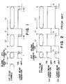
- This recording has generally been performed by irradiating with a laser beam for a period of time corresponding to length of a pit to be formed (e.g., 231 nsec for 1T in a Compact Disc) as shown in (a) in Fig. 2 or by irradiating laser beam for a period of time corresponding to length of a pit to be formed minus a predetermined length of time t0 as shown in (b) of Fig. 2 (EP-A-0 213 623).
- Pit length or blank length can be set at various values depending upon consecutive times of occurrence of "1" or "0" of data to be recorded (e.g., 3T to 11T in a Compact Disc format). Since time length during which laser beam is irradiated increases with increase in the pit length, the degree of heating of the recording film increases with increase in the pit length with a result that the recording film tends to be melted more quickly as the pit length increases. This phenomenon becomes more remarkable as heat conductivity of the recording film becomes larger relative to the linear velocity of the rotating disc.
- the length of a pit varies also depending upon the length of a blank immediately before the pit (hereinafter referred to as "immediately preceding blank length").
- immediately preceding blank length decreases, degree of influence of heating made in forming an immediately preceding pit on forming a next pit increases with a result that the recording film is melted more quickly in forming the next pit. Accordingly, even if radiation time of laser beam is the same, pit length of an actually formed pit increases as the immediately preceding blank length decreases.
- Fig. 10 shows an example of variation of pit length of an actually formed pit depending upon immediately preceding blank length with respect to pits of 3T, 7T and 11T.
- combination of pit length and blank length of the same time length is taken as reference Ref for each pit length and deviation from the reference Ref for each pit length is plotted.
- immediately preceding blank length decreases, the recording film is melted more quickly due to influence of heating made in forming a preceding pit so that the pit length increases despite the same radiation time of laser beam. This causes jitter in a reproduced signal with resulting occurrence of errors and deterioration in the signal-to-noise ratio in the reproduced signal.
- the variation in immediately preceding blank length causes variation not only in pit length but also in relationship between a radiation start position and a pit starting end position of a pit formed by the radiation. That is, as immediately preceding blank length increases, distance between the radiation start position and the pit starting end position increases. This is because influence of heat from an immediately preceding pit decreases as the immediately preceding blank length increases with a result that it becomes harder to melt the recording film.
- an object of the invention to reduce errors in pit length and blank length and thereby decrease jitter in a reproduced signal for reducing errors and improving the signal-to-noise ratio in the reproduced signal.
- optical disc recording device achieving the above described object of the invention as defined in claim 2 to relatively shorten radiation time of laser beam when a pit of a smaller immediately preceding blank length is to be formed.
- optical disc recording device achieving the above described object of the invention as defined in appended claim 3 to advance starting of radiation of laser beam when an immediately preceding blank length of a pit to be formed increases.
- the pit starting end position tends to be increasingly deviated behind relative to the radiation start position as immediately preceding blank length increases, advancing of starting of radiation of laser beam in forming a pit after a larger immediately preceding blank length enables adjusting of the pit starting end position to a predetermined position whereby blank length which is closer to a set value can be obtained and jitter in a reproduced signal can further be reduced.
- FIG. 5 which shows a portion of a DRAW disc recording device embodying the invention including an optical head and its peripheral circuits.
- the entire structure of the recording device can be constructed, for example, of a structure shown in the same applicant's copending Japanese Patent Application No. 307372/1986.
- a DRAW disc 11 is made of a substrate of glass, synthetic resin or other material and a metal layer of a suitable metal such as tellurium coated on the substrate.
- a plurality of tracks of pregroove are spirally preformed on this disc 11.
- data and address are written by tracking these tracks at a predetermined constant linear velocity.
- recorded address is read and recorded data is read out from the desired address.
- Recording of data on the disc 11 is made by melting the metal layer of the disc 11 with recording laser beam for forming pits. Reproduction of data is made by detecting the pits by reflection of reproducing laser beam.
- An optical head 13 effects recording or reproduction of data by irradiating recording or reproducing laser beam generated by a laser beam generation circuit 14 on the surface of the disc 11 which is rotated at a constant linear velocity.
- Level of laser beam is controlled by a level control signal so that the level is larger during recording than during reproduction.
- laser beam generated by the laser beam generation circuit 14 is irradiated on the surface of the disc 11 after data to be written is modulated into plurally divided pulses by a pulse division circuit 12. Radiation time of this recording laser beam is controlled in accordance with pit length and immediately preceding blank length of a pit to be formed and pit length of a substantially predetermined value can be obtained regardless of magnitudes of pit length and blank length.
- the pulse division circuit 12 and the laser beam generation circuit 14 irradiate laser beam for a period of time corresponding to pit length of a pit to be formed. These circuits also correct the radiation time and timing of start of radiation of laser beam in accordance with pit length and immediately preceding blank length of the pit to be formed so that a substantially predetermined pit length can be formed at a substantially predetermined position. The correction of the radiation time and the timing of start of radiation will be described more fully below.
- a pit of pit length which is close to a predetermined value can be formed regardless of magnitude of immediately preceding blank length.
- jitter in the reproduced signal is reduced so that occurrence of errors is reduced and the signal-to-noise ratio is improved in the reproduced signal.
- the pit starting end position tends to be increasingly deviated behind relative to the radiation start position as immediately preceding blank length increases.
- correction of radiation time in accordance with immediately preceding blank length is performed in a starting end portion of radiation time (i.e., in such a manner that the amount of correction is added to the starting end portion) as shown in (b) of Fig. 9.
- This arrangement enables a pit to be formed at a correct position whereby a correct blank length can be obtained.
- Fig. 9 to represents constant time.
- pit length of a pit to be formed is influenced by pit length and immediately preceding blank length
- pit length which is closer to a predetermined value can be obtained by determining amount of correction by combination of pit length and immediately preceding blank length.
- An example of radiation time obtained by various combinations of pit length and immediately preceding blank length is shown in the following Table 3:
- a pit can be formed at a predetermined position so that a correct blank length can also be obtained.
Landscapes
- Physics & Mathematics (AREA)
- Optics & Photonics (AREA)
- Optical Recording Or Reproduction (AREA)
Claims (3)
- Optische Plattenaufzeichnungsvorrichtung, bei der Daten auf einer optischen Platte (11) aufgezeichnet werden können, indem Pits durch Laserstrahlbestrahlung über Zeitspannen erzeugt werden, die der Länge der jeweiligen zu bildenden Pits entsprechen, mit einer Laserstrahlsteuereinrichtung (14), die eine Korrektureinrichtung zum Verkürzen der Strahlungsdauer des Laserstrahls in bezug auf die der Länge des zu bildenden Pits entsprechende Zeit um einen vorbestimmten Korrekturbetrag (t) aufweist, dadurch gekennzeichnet, daß die Korrektureinrichtung mit zunehmender Länge des zu bildenden Pits eine Erhöhung des Korrekturbetrags bewirkt.
- Optische Plattenaufzeichnungsvorrichtung, bei der Daten auf einer optischen Platte (11) aufgezeichnet werden können, indem Pits durch Laserstrahlbestrahlung über Zeitspannen erzeugt werden, die der Länge der jeweiligen zu bildenden Pits entsprechen, mit einer Laserstrahlsteuereinrichtung (14), die eine Korrektureinrichtung zum Verkürzen der Strahlungsdauer des Laserstrahls in bezug auf die der Länge des zu bildenden Pits entsprechende Zeit um einen vorbestimmten Korrekturbetrag (t) aufweist, dadurch gekennzeichnet, daß die Korrektureinrichtung mit abnehmender Länge der den zu bildenden Pits unmittelbar vorangehenden Leerstellen eine Erhöhung des Korrekturbetrags bewirkt.
- Optische Plattenaufzeichnungsvorrichtung, bei der Daten auf einer optischen Platte (11) aufgezeichnet werden können, indem Pits durch Laserstrahlbestrahlung über Zeitspannen erzeugt werden, die der Länge der jeweiligen zu bildenden Pits entsprechen, mit einer Laserstrahlsteuereinrichtung zum Steuern der Bestrahlungsdauer, dadurch gekennzeichnet, daß die Laserstrahlsteuereinrichtung das Vorverlegen des Beginns der Laserstrahlbestrahlung in bezug auf die Position des zu bildenden Pits um einen Betrag bewirkt, der mit der Länge der dem zu bildenden Pit unmittelbar vorangehenden Leerstelle zunimmt.
Applications Claiming Priority (4)
| Application Number | Priority Date | Filing Date | Title |
|---|---|---|---|
| JP105247/87 | 1987-04-28 | ||
| JP62105247A JP2543362B2 (ja) | 1987-04-28 | 1987-04-28 | 光デイスク記録装置 |
| JP62137915A JPH065576B2 (ja) | 1987-06-01 | 1987-06-01 | 光ディスク記録装置 |
| JP137915/87 | 1987-06-01 |
Publications (3)
| Publication Number | Publication Date |
|---|---|
| EP0289260A2 EP0289260A2 (de) | 1988-11-02 |
| EP0289260A3 EP0289260A3 (en) | 1990-08-01 |
| EP0289260B1 true EP0289260B1 (de) | 1992-07-22 |
Family
ID=26445571
Family Applications (1)
| Application Number | Title | Priority Date | Filing Date |
|---|---|---|---|
| EP88303739A Expired EP0289260B1 (de) | 1987-04-28 | 1988-04-26 | Optische Plattenaufzeichnungsvorrichtung |
Country Status (3)
| Country | Link |
|---|---|
| US (1) | US4998237A (de) |
| EP (1) | EP0289260B1 (de) |
| DE (1) | DE3872926T2 (de) |
Families Citing this family (30)
| Publication number | Priority date | Publication date | Assignee | Title |
|---|---|---|---|---|
| DE3888565T2 (de) * | 1987-04-28 | 1994-10-20 | Sharp Kk | Aufzeichnungs- und Wiedergabegerät. |
| US5111443A (en) * | 1988-11-02 | 1992-05-05 | Pioneer Electronic Corporation | Optical recording apparatus |
| US5214627A (en) * | 1989-02-08 | 1993-05-25 | Fujitsu Limited | Optical disk having read-exclusive and write-enable regions |
| JPH077509B2 (ja) * | 1989-02-20 | 1995-01-30 | オムロン株式会社 | 2光源方式光学的記録再生装置 |
| JP2708859B2 (ja) * | 1989-03-16 | 1998-02-04 | 三洋電機株式会社 | 光ディスク記録装置 |
| JPH0810490B2 (ja) * | 1989-03-20 | 1996-01-31 | 富士通株式会社 | 光ディスク情報書込制御方法およびその装置 |
| JP2785370B2 (ja) * | 1989-08-25 | 1998-08-13 | ソニー株式会社 | 光記録装置 |
| JP2984004B2 (ja) * | 1989-08-28 | 1999-11-29 | ソニー株式会社 | カッテングマシン |
| US5128921A (en) * | 1989-09-28 | 1992-07-07 | Tandy Corporation | Method and apparatus for pre-compensation in an optical disc |
| DE69030656T2 (de) * | 1989-12-20 | 1997-10-23 | Sony Corp | Optisches aufzeichnungsgerät |
| NL9000150A (nl) * | 1990-01-22 | 1991-08-16 | Philips Nv | Werkwijze en inrichting voor het aanbrengen van een patroon van gebiedjes met veranderde optische eigenschappen in een registratiedrager. |
| US5408456A (en) * | 1990-02-02 | 1995-04-18 | Canon Kabushiki Kaisha | Data reproducing method and apparatus for determining the interval between pits on a recording medium from a modulated read-out signal |
| JP2893091B2 (ja) * | 1990-06-18 | 1999-05-17 | 株式会社リコー | 光学的情報記録方法 |
| JP2852792B2 (ja) * | 1990-07-05 | 1999-02-03 | 三菱電機株式会社 | 光ディスク装置 |
| US5537379A (en) | 1991-05-10 | 1996-07-16 | Discovision Associates | Optical data storage and retrieval system and method |
| EP0817179B1 (de) * | 1991-05-10 | 2001-07-25 | Discovision Associates | System und Verfahren zur optischen Speicherung und Wiedergewinnung von Daten |
| JP2639279B2 (ja) * | 1992-05-08 | 1997-08-06 | ヤマハ株式会社 | 光ディスク記録装置 |
| US5400313A (en) * | 1992-11-09 | 1995-03-21 | International Business Machines Corporation | Optical data storage system and method with reduced heat buildup |
| US5530688A (en) * | 1994-10-31 | 1996-06-25 | International Business Machines Corporation | Optical disk recording device using two modulated laser beams for recording information data |
| US5561656A (en) * | 1994-11-18 | 1996-10-01 | International Business Machines Corporation | Pulse width modulation optical disk drive with pulsed laser preheating between marks |
| US5631887A (en) * | 1996-04-30 | 1997-05-20 | International Business Machines Corporation | Pulse width modulation optical disk drive with adjustable pulsed laser write and preheat patterns |
| JPH11144288A (ja) * | 1997-11-05 | 1999-05-28 | Yamaha Corp | 光ディスク記録のレーザパワー制御方法および光ディスク記録装置のレーザダイオード駆動回路 |
| US6781937B2 (en) * | 1998-01-21 | 2004-08-24 | Yamaha Corporation | Optical disk recording method and device |
| KR100320470B1 (ko) * | 1999-03-05 | 2002-01-12 | 구자홍 | 광 디스크 기록신호 생성 방법 및 장치 |
| JP2001266413A (ja) * | 2000-03-17 | 2001-09-28 | Toshiba Corp | 光ディスク、光ディスク再生装置、及び光ディスク再生方法 |
| US6697308B1 (en) * | 2000-04-28 | 2004-02-24 | Mosel Vitelic Corporation | Method and system for providing timing adjustment to perform reliable optical recording at high speeds |
| US6741547B2 (en) | 2000-08-10 | 2004-05-25 | Ricoh Company, Ltd. | Optical recording medium having short wobble period length |
| US7144677B2 (en) | 2001-03-21 | 2006-12-05 | Ricoh Company, Ltd. | Optical recording method and optical recording medium |
| JP2002298350A (ja) * | 2001-03-28 | 2002-10-11 | Tdk Corp | 光記録方法、光記録装置及び光記録媒体 |
| JP2003323717A (ja) * | 2002-05-02 | 2003-11-14 | Pioneer Electronic Corp | 情報記録再生装置および情報記録方法 |
Family Cites Families (7)
| Publication number | Priority date | Publication date | Assignee | Title |
|---|---|---|---|---|
| JPS563438A (en) * | 1979-06-25 | 1981-01-14 | Hitachi Ltd | Optical information recording method |
| JPS563441A (en) * | 1979-06-25 | 1981-01-14 | Hitachi Ltd | Optical information recorder |
| JPS5778637A (en) * | 1980-10-31 | 1982-05-17 | Matsushita Electric Ind Co Ltd | Optical information recorder |
| JPS5922239A (ja) * | 1982-07-28 | 1984-02-04 | Fujitsu Ltd | 光学的記録制御方式 |
| JPS6137225A (ja) * | 1984-07-31 | 1986-02-22 | リツカ−ホ−ムメンテナンス株式会社 | 水溶性消泡剤を用いた洗剤の捕集方法ならびに装置 |
| EP0213623B1 (de) * | 1985-09-02 | 1996-01-10 | Sharp Kabushiki Kaisha | Wiedergabegerät für optische Platten |
| US4873680A (en) * | 1987-03-13 | 1989-10-10 | Laserdrive Ltd. | Apparatus and method for detecting and compensating for pit extension in an optical disk recording system |
-
1988
- 1988-04-25 US US07/185,701 patent/US4998237A/en not_active Expired - Lifetime
- 1988-04-26 DE DE8888303739T patent/DE3872926T2/de not_active Expired - Lifetime
- 1988-04-26 EP EP88303739A patent/EP0289260B1/de not_active Expired
Also Published As
| Publication number | Publication date |
|---|---|
| DE3872926T2 (de) | 1992-12-03 |
| EP0289260A2 (de) | 1988-11-02 |
| DE3872926D1 (de) | 1992-08-27 |
| EP0289260A3 (en) | 1990-08-01 |
| US4998237A (en) | 1991-03-05 |
Similar Documents
| Publication | Publication Date | Title |
|---|---|---|
| EP0289260B1 (de) | Optische Plattenaufzeichnungsvorrichtung | |
| US5003527A (en) | System for recording optical discs for use with optical disc playback only devices | |
| US5802032A (en) | Method and device for recording a mark having a substantially constant number of pulses per unit length independent of writing speed on an optical information carrier | |
| EP0957475B1 (de) | Optisches aufzeichnungsverfahren und optisches aufzeichnungsgerät | |
| EP0932144B1 (de) | Aufzeichnungsvorrichtungen für optische Platte | |
| US5412626A (en) | Method of recording optical information with selective correction in pulse waveform and a recording system therefor | |
| EP0902424A1 (de) | Informationsaufzeichnungsverfahren und -gerät zur Verminderung von Jitter am Musterrand | |
| JP3266971B2 (ja) | 光学情報の記録方法 | |
| US7342861B2 (en) | Method and apparatus for recording data on an optical recording medium | |
| US6996047B2 (en) | Optical disc recording method and apparatus | |
| EP0712119B1 (de) | Aufzeichnungsverfahren, Aufzeichnungsgerät, Wiedergabeverfahren und Wiedergabegerät für eine optische Platte | |
| US5513167A (en) | Optical recording apparatus | |
| JP2560298B2 (ja) | 光デイスク記録装置 | |
| US6751513B1 (en) | Method and device for recording an optical information carrier | |
| US6208601B1 (en) | Optical information recording method and apparatus | |
| EP0821825B1 (de) | Verfahren und vorrichtung zur aufzeichnung eines optischen informationsträgers | |
| JP3473423B2 (ja) | 光ディスク記録方法および光ディスク記録装置 | |
| JP3271575B2 (ja) | 光ディスク記録装置 | |
| EP0458975B1 (de) | Optisches aufzeichnungsgerät | |
| JP2543362B2 (ja) | 光デイスク記録装置 | |
| US20010043531A1 (en) | Optical recording apparatus | |
| JP2692534B2 (ja) | 光ディスク記録方法 | |
| JPH1083573A (ja) | 光ディスク記録担体 | |
| JPH065576B2 (ja) | 光ディスク記録装置 | |
| JP2002100048A (ja) | 光ディスク記録方法 |
Legal Events
| Date | Code | Title | Description |
|---|---|---|---|
| PUAI | Public reference made under article 153(3) epc to a published international application that has entered the european phase |
Free format text: ORIGINAL CODE: 0009012 |
|
| 17P | Request for examination filed |
Effective date: 19880506 |
|
| AK | Designated contracting states |
Kind code of ref document: A2 Designated state(s): DE GB NL |
|
| PUAL | Search report despatched |
Free format text: ORIGINAL CODE: 0009013 |
|
| AK | Designated contracting states |
Kind code of ref document: A3 Designated state(s): DE GB NL |
|
| 17Q | First examination report despatched |
Effective date: 19911031 |
|
| GRAA | (expected) grant |
Free format text: ORIGINAL CODE: 0009210 |
|
| AK | Designated contracting states |
Kind code of ref document: B1 Designated state(s): DE GB NL |
|
| REF | Corresponds to: |
Ref document number: 3872926 Country of ref document: DE Date of ref document: 19920827 |
|
| PLBE | No opposition filed within time limit |
Free format text: ORIGINAL CODE: 0009261 |
|
| STAA | Information on the status of an ep patent application or granted ep patent |
Free format text: STATUS: NO OPPOSITION FILED WITHIN TIME LIMIT |
|
| 26N | No opposition filed | ||
| REG | Reference to a national code |
Ref country code: GB Ref legal event code: IF02 |
|
| PGFP | Annual fee paid to national office [announced via postgrant information from national office to epo] |
Ref country code: NL Payment date: 20070403 Year of fee payment: 20 |
|
| PGFP | Annual fee paid to national office [announced via postgrant information from national office to epo] |
Ref country code: DE Payment date: 20070419 Year of fee payment: 20 |
|
| PGFP | Annual fee paid to national office [announced via postgrant information from national office to epo] |
Ref country code: GB Payment date: 20070425 Year of fee payment: 20 |
|
| REG | Reference to a national code |
Ref country code: GB Ref legal event code: PE20 Expiry date: 20080425 |
|
| PG25 | Lapsed in a contracting state [announced via postgrant information from national office to epo] |
Ref country code: NL Free format text: LAPSE BECAUSE OF EXPIRATION OF PROTECTION Effective date: 20080426 |
|
| NLV7 | Nl: ceased due to reaching the maximum lifetime of a patent |
Effective date: 20080426 |
|
| PG25 | Lapsed in a contracting state [announced via postgrant information from national office to epo] |
Ref country code: GB Free format text: LAPSE BECAUSE OF EXPIRATION OF PROTECTION Effective date: 20080425 |