EP0285314A1 - Dispositif de diagnostic ophtalmologique - Google Patents
Dispositif de diagnostic ophtalmologique Download PDFInfo
- Publication number
- EP0285314A1 EP0285314A1 EP88302544A EP88302544A EP0285314A1 EP 0285314 A1 EP0285314 A1 EP 0285314A1 EP 88302544 A EP88302544 A EP 88302544A EP 88302544 A EP88302544 A EP 88302544A EP 0285314 A1 EP0285314 A1 EP 0285314A1
- Authority
- EP
- European Patent Office
- Prior art keywords
- eye fundus
- image plane
- speckle
- light
- optical system
- Prior art date
- Legal status (The legal status is an assumption and is not a legal conclusion. Google has not performed a legal analysis and makes no representation as to the accuracy of the status listed.)
- Granted
Links
- 238000003745 diagnosis Methods 0.000 title claims abstract description 14
- 230000003287 optical effect Effects 0.000 claims abstract description 34
- 230000017531 blood circulation Effects 0.000 claims description 27
- 238000012545 processing Methods 0.000 claims description 7
- 238000001228 spectrum Methods 0.000 claims description 5
- 210000004204 blood vessel Anatomy 0.000 abstract description 46
- 238000005259 measurement Methods 0.000 abstract description 12
- 238000001514 detection method Methods 0.000 abstract description 9
- 230000008901 benefit Effects 0.000 abstract description 5
- 238000000034 method Methods 0.000 description 18
- 238000010586 diagram Methods 0.000 description 11
- 238000001914 filtration Methods 0.000 description 8
- 238000000926 separation method Methods 0.000 description 8
- 210000000601 blood cell Anatomy 0.000 description 7
- 230000000694 effects Effects 0.000 description 3
- 238000011156 evaluation Methods 0.000 description 3
- 238000005286 illumination Methods 0.000 description 3
- 230000015572 biosynthetic process Effects 0.000 description 2
- 238000007796 conventional method Methods 0.000 description 2
- 230000006870 function Effects 0.000 description 2
- 230000007246 mechanism Effects 0.000 description 2
- 239000013307 optical fiber Substances 0.000 description 2
- 210000004369 blood Anatomy 0.000 description 1
- 239000008280 blood Substances 0.000 description 1
- 230000015556 catabolic process Effects 0.000 description 1
- 210000004087 cornea Anatomy 0.000 description 1
- 238000006731 degradation reaction Methods 0.000 description 1
- 239000000463 material Substances 0.000 description 1
- 238000000691 measurement method Methods 0.000 description 1
- 238000012986 modification Methods 0.000 description 1
- 230000004048 modification Effects 0.000 description 1
- 238000012544 monitoring process Methods 0.000 description 1
- 230000003595 spectral effect Effects 0.000 description 1
Images


Classifications
-
- A—HUMAN NECESSITIES
- A61—MEDICAL OR VETERINARY SCIENCE; HYGIENE
- A61B—DIAGNOSIS; SURGERY; IDENTIFICATION
- A61B3/00—Apparatus for testing the eyes; Instruments for examining the eyes
- A61B3/10—Objective types, i.e. instruments for examining the eyes independent of the patients' perceptions or reactions
- A61B3/12—Objective types, i.e. instruments for examining the eyes independent of the patients' perceptions or reactions for looking at the eye fundus, e.g. ophthalmoscopes
- A61B3/1225—Objective types, i.e. instruments for examining the eyes independent of the patients' perceptions or reactions for looking at the eye fundus, e.g. ophthalmoscopes using coherent radiation
Definitions
- This invention relates to an ophthalmological diagnosis apparatus, and more particularly to an ophthalmological diagnosis apparatus whereby the eye fundus is illuminated by a beam of laser light and the movement of a speckle pattern formed by diffused laser light reflected by the tissue of the fundus at an image plane which is conjugate with the eye fundus is detected as fluctuation in the speckle light intensity to measure the blood flow state for ophthalmological diagnosis.
- the optical system is complex and needs to be high-precision.
- the fact that the angle of beam incidence or light detection has to be known in advance, the fact that a laser beam adjusted to a beam diameter that is substantially equal to the diameter of the blood vessel concerned (which generally measures between several tens and several hundred micrometers) has to be directed onto the blood vessel with high precision, and the fact that the person undergoing examination has to be kept motionless during the period of measurement make these methods extremely difficult to apply clinically and impair the repeatability and reliability of the results thereby obtained.
- the movement of the speckle pattern formed at the Fraunhofer diffraction plane with respect to the object plane or at an image plane that is conjugate with respect to the eye fundus is then detected as fluctuations in light intensity by means of finite detecting apertures, and is analyzed to thereby measure the state of blood flow in the eye fundus.
- the speckle pattern formed at the Fraunhofer diffraction plane consists of superposed fields of light scattered from all of the scattering points within the region of the fundus illuminated by the laser beam.
- light scattered from blood cells in the target blood vessel is superposed with light scattered from the blood cells of adjacent blood vessels, making it difficult to evaluate the blood flow in any one specific blood vessel.
- light scattered by the walls of blood vessels and surrounding tissue is also included, which forms optical background noise with respect to the light that is scattered by the blood cells in the target blood vessel. This has made it difficult to detect signals having a good S/N (signal/noise) ratio at the Fraunhofer diffraction plane.
- This object of the invention is accomplished by providing an arrangement having an optical spatial frequency filter at a spatial frequency plane, a double diffraction optical system whereby an eye fundus image formed at a first image plane that is conjugate with the eye fundus is reformed at a second image plane, a magnifying optical system for expanding the eye fundus image formed on the second image plane, and a detecting aperture for detecting movement of a laser speckle pattern formed at the image plane of the magnifying optical system as fluctuations in the intensity of the speckle light, whereby ophthalmological diagnosis is performed by processing speckle signals obtained by means of the detecting aperture.
- the image plane is prescribed for detection of the speckle pattern and fluctuations in the intensity of the speckle light at the plane are acquired as signals, enabling the desired blood vessel to be specifically set at the image plane.
- detection of the speckle light is performed following double diffraction, spatial frequency filtering, and image formation using a microscope optical system, a specific blood vessel can be readily selected, unnecessary light can be excluded, and speckle light can be detected with a good S/N ratio.
- this arrangement enables the velocity of the blood flowing through a single specific blood vessel to be measured.
- this arrangement involves none of the restrictively high level of precision that is required of optical systems utilizing the Doppler method, it has good operability and, therefore, yields data having good reproducibility.
- the invention is concerned specifically with the fundus region of the eye, and as such the following description relates to when an eye fundus camera is used to measure blood flow in the eye fundus.
- FIG. 1 shows an overall schematic view of an apparatus for carrying out the measurement method according to the present invention.
- a laser beam such as from a green-light He-Ne (wavelength: 543.5nm) type laser beam source 1, for example, passes through a condenser lens 1 ⁇ , and then through a light intensity adjustment filter 2 for adjusting the intensity of the beam. Thereafter the beam passes through relay lenses 3 and 4 and is introduced into the eye fundus illuminating optical system of an eye fundus camera.
- a pair of stops 5 and 6 is disposed between the relay lenses 3 and 4 for selectively adjusting the size and shape of the region of the eye fundus irradiated by the laser beam.
- a shutter 7 Disposed near the beam-emitting end of the laser beam source 1 is a shutter 7 which can be opened or closed as required.
- the laser beam issuing from the relay lens 4 is reflected by a mirror 9 provided in one portion of an annular aperture 8a formed in a ring slit 8 disposed in the eye fundus illuminating optical system, so that the reflected laser beam travels along the same light path leading to the eye fundus under examination as that followed by a beam of light directed onto the eye fundus as illumination for photography and observation.
- the laser beam passes through relay lenses 10 and 11, is reflected by a ring mirror 12, is converged on the cornea 13a of the eye under examination 13 by an objective lens 13 ⁇ and then diverges as it moves toward the eye fundus 13b which it reaches in a diverged state to thereby form an illuminated region which is larger than the diameter of the blood vessel referred to earlier.
- This illuminated area is also illuminated by the illuminating projector of the fundus camera, facilitating observation.
- the system for providing the illumination for observation is constituted of an observation light source 22, a condenser lens 23, a condenser lens 25, a filter 27 and a mirror 26 disposed on the same light path as a photographic light source 24.
- the path of the laser beam coincides with that of the beam of photographic and observation light, the laser beam can be made to impinge on the desired region of the eye fundus 13b by use of the mechanisms for swinging and tilting the eye fundus camera vertically and horizontally and also by use of the eye fixation means.
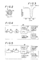
- the filter 27 disposed between the condenser lens 25 and the mirror 26 is a wavelength separation filter which, having the type of characteristics shown in Figure 3, filters out green components from the observation and photographic light.
- the wavelength separation mirror 15 exhibits the type of spectral characteristics illustrated in Figure 3, and since it therefore reflects almost all light components having wavelengths in the green band and passes other light components, it reflects most of the speckle light (green) generated by the He-Ne laser beam.
- a lens 16 images the reflected light at an image plane 34, and an image is again formed at a plane 35 by a double diffraction system comprised of lenses 17 and 17 ⁇ .
- the eye fundus image thus filtered and reformed is then magnified by an objective lens 19a and eyepiece lens 19b of a microscope optical system 19.
- the magnified image passes through a detecting aperture 20, is converged once again by a condenser lens 21 and detected by a photomultiplier 40.
- a shutter 40 ⁇ is disposed in front of the photomultiplier 40 and the output signal produced by the photomultiplier 40 and obtained therefrom when this shutter is open is fed into a signal processor 50.
- the signal processor 50 is constituted of an amplifier 51, a filter 52, an A/D (analog/digital) converter 53, a CPU 54, a CRT display 55, a printer 56, a memory 57 and a keyboard 58.
- a photon counting unit 51 ⁇ is provided in front of the amplifier 51, as shown in Figure 5.
- the light passing through the wavelength separation mirror 15 advances through a relay lens 28, is reflected by a swingable mirror 29 and a mirror 30, and is then directed, via a reticle 31, to an eyepiece 33 through which it can be observed or recorded on a photographic film 32.
- the eye fundus 13b of the eye 13 under examination is observed by means of the observation light optical system constituted by the elements 22 to 26 and the laser light beam source 1 is activated.
- the filter 2 is used to adjust the light output to the level used for system set-up and the stops 5 and 6 are used to set the size and shape of the region illuminated by the laser beam.
- the shutter 7 is opened and, after the measurement position has been set, the speckle pattern is confirmed by means of the observation light optical system constituted by the elements 28 to 31.
- the region of the eye fundus 13b illuminated by the laser beam at the portions at which measurement is to be carried out is set larger than the blood vessel, for example to a diameter of 1mm to 3mm.
- the detection is conducted at the Fraunhofer plane the detected light will consist of superposed rays of light scattered from all the points within the illuminated region.
- blood flow information obtained from an analysis of the speckle signals will be an averaged evaluation of the state of the blood flow in all the blood vessels falling within the irradiated region. It is because of this that it has been difficult to measure the blood flow in a specific single blood vessel.
- light scattered from the walls of blood vessels and surrounding tissue is also detected, forming optical background noise which degrades the S/N ratio of the speckle signals.
- detection of the speckle pattern is conducted at a magnified image plane.
- a conjugate image of the eye fundus is formed at the image plane 34 shown in Figure 1. Further, the image is again formed at the plane 35 by the double diffraction system comprised of lenses 17 and 17 ⁇ .
- This image is then magnified by the objective lens 19a and eyepiece lens 19b of the microscope optical system 19, and fluctuations in the intensity of the speckle light are detected by the detecting aperture 20 disposed at the plane of the magnified image.
- the light is then converged by a condenser lens 21 and converted into an electrical signal by the photomultiplier 40, the shutter 40 ⁇ being in the open position.
- the output produced by the photomultiplier 40 during measurement constitutes a speckle signal which varies with time in accordance with the movement of the blood cells.
- This speckle signal is amplified by an amplifier 51 provided within a signal processor 50, and if necessary it is then passed through a band pass filter 52 the band of which is set so as to remove unnecessary frequency components.
- the signal is then converted into digital form by an A/D converter 53, after which it is subjected to frequency analysis by the execution of a frequency analysis program prepared in advance, and the power spectrum distribution is thereby obtained.
- the detecting aperture 20 is disposed at the magnified image plane, the blood flow in a specific single blood vessel can be measured by selecting the blood vessel image to be measured in the image area of the region illuminated by the laser beam and locating the detecting aperture 20 within the blood vessel image, either by adjusting the position of the detecting aperture 20 or by adjusting the fixation of the eye under examination 13, Therefore, by employing the detection method and signal processing described below, it becomes possible to elucidate the blood flow not as a state but as an absolute velocity value.
- the laser Doppler method mentioned in the above.
- the blood vessel concerned is illuminated using laser light tightly focused to form a very fine beam with a diameter substantially equal to or smaller than the diameter of the blood vessel upon which the beam impinges at a predetermined angle, or alternatively, the incident laser beam is split into two beams that are directed so that they intersect at a position within the said blood vessel.
- the operations required for this are extremely difficult, the optical system complex and the obtained data inconsistent.
- the embodiment according to the present invention is based on the speckle method, it is very practical because, with respect to relatively large blood vessels, it permits a single specific blood vessel to be selected and the absolute velocity of the blood flow therein to be measured. That is, it enables the absolute velocity of the blood flow in a specific blood vessel to be measured while utilizing the advantages of the speckle method. Because the laser beam is sufficiently larger than the diameter of the blood vessel concerned the vessel does not shift out of the beam, and as the detecting aperture is positioned at a magnified image plane, adjustment is very simple.
- a pinhole may be utilized as the detecting aperture 20.
- a pinhole such as the pinhole 61 shown in Figure 7 having a smaller diameter than that of the blood vessel, as observed in the image, is disposed at a portion where the image plane speckles within the vessel are in motion, speckles passing across the detecting aperture 20 will give rise to a corresponding fluctuation in the intensity of the detected light, thereby producing a speckle signal.
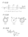
- a detecting aperture 20 that can be employed is that of a slit 63 shown in Figure 10.
- the length l of the slit 63 is less than the diameter of the blood vessel on the magnified image plane and that the width ⁇ thereof is less than the length l and as large or larger than the image plane speckle size.
- the slit is disposed so that its long side is perpendicular to the orientation of the blood vessel, that is, perpendicular to the direction of image plane speckle movement.
- the pinhole 61 is non-directional there is no need to adjust its orientation, but the slit 63 does require to be aligned perpendicularly with respect to the direction of the blood flow in the vessel.
- One way of doing this is to make the slit aperture a rotatably adjustable mechanism that is linked to a reticle 64 constituted of x-axis and y-axis crosshairs, as shown in Figure 11, and disposed at an image plane 36 formed in front of the eyepiece 33 of the eye fundus camera shown in Figure 1.
- One method that can be applied is to use the reticle to bring the y-axis into alignment with the target blood vessel so that the point at which the crosshairs intersect is at the center of the blood vessel, and then to position the slit at the magnified image plane so that it is perpendicular to the direction of the blood flow and, in addition, the center of the slit coincides with the center of the blood vessel.
- the double diffraction system and spatial filtering will now be described in more detail.
- laser speckle light reflected by the wavelength separation mirror 15 is formed by the lens 16 into an image of the region of the eye fundus illuminated by the laser beam.
- the type of generally-known double-diffraction and spatial frequency filtering method shown in Figure 12 is resorted to.
- the lens 17 is positioned so it is separated from the image plane 34 by just a focal distance F which produces a spatial frequency plane at distance F to the rear of the lens 17.
- a low-pass filter constituted of a finite aperture 18a with the optical axis at the center thereof, such as the one illustrated in Figure 13(A), is used as the spatial frequency filter 18 when the reflected light to be filtered out has a pronounced edgewise bend.
- a high-pass filter with a center optical axis is used constituted of an optical baffle 18b of a predetermined diameter, as shown in Figure 13(B).
- the said aperture 18a and baffle 18b can be combined to form the type of band pass filter shown in Figure 13(C). Which of these is selected depends on the image conditions. Also, the diameters of the aperture 18a and the baffle 18b may be made variable.
- the light source utilized in the apparatus is a laser light source.
- the location of the image formation plane 34 is equivalent to that of the photographic film plane 32.
- the photographic lens 14 are used to adjust the focus as required for each fundus concerned. Even if the lenses 14 are moved by this adjustment, at the film plane 32 the image stays in constant focus. Therefore, an image that is constantly in focus can also be obtained at the image plane 34 that is optically equivalent to the film plane 32, which is effective with respect to the practical utilization of the embodiment illustrated in Figure 1.
- the speckle light detected by the detecting aperture 20 and converged by the condenser lens 21, in the embodiment illustrated in Figure 1, is directed via an optical fiber 37 and a lens 38 into the photomultiplier 40, as illustrated in Figure 14, where it can be converted into electrical signals.
- This arrangement makes it possible to separate the photomultiplier 40 from the main unit of the apparatus, which is of practical benefit.
- This apparatus according to the invention retains the original fundus camera functions, so it is possible to make a photographic record for the purpose of comparison with the results of the blood flow measurements, and monitoring during measurement is also possible.
- a green-light He-Ne laser (wavelength: 543.5nm) is used as the light source.
- the method is precisely the same with respect to the use of, for example, a blue-light Ar laser (wavelength: 488.0nm), or a red-light He-Ne laser (wavelength: 637.8nm). If the light source wavelength is changed, all that has to be done is to use wavelength separation mirrors 27 and 15 ( Figure 1) with wavelength separation regions that match the wavelength of the light source.
- the present invention as described in the foregoing, double diffraction and spatial frequency filtering are carried out, an image is formed by means of a optical magnifying system, and a specific blood vessel is then selected for detection and evaluation of speckle signals.
- This enables the absolute velocity value of the blood flow in a single specific blood vessel to be found.
- the present invention also facilitates the measurement of the blood flow state with good reproducibility and it has good operability, and as such is highly effective as an ophthalmological diagnosis apparatus.
- the optical system employed does not require the type of precision that is required by methods such as the Doppler method, the apparatus is easy to be realized.
- the image plane has an ample amount of light for detection purposes, the time required for measurement can be shortened, easing the strain on the person being examined.
- the apparatus also possesses the original functions of an eye fundus camera, so it has a high clinical utility.
Landscapes
- Life Sciences & Earth Sciences (AREA)
- Health & Medical Sciences (AREA)
- Medical Informatics (AREA)
- Molecular Biology (AREA)
- Ophthalmology & Optometry (AREA)
- Engineering & Computer Science (AREA)
- Biomedical Technology (AREA)
- Heart & Thoracic Surgery (AREA)
- Physics & Mathematics (AREA)
- Biophysics (AREA)
- Surgery (AREA)
- Animal Behavior & Ethology (AREA)
- General Health & Medical Sciences (AREA)
- Public Health (AREA)
- Veterinary Medicine (AREA)
- Eye Examination Apparatus (AREA)
- Measuring Pulse, Heart Rate, Blood Pressure Or Blood Flow (AREA)
Applications Claiming Priority (2)
| Application Number | Priority Date | Filing Date | Title |
|---|---|---|---|
| JP62075778A JPH06100B2 (ja) | 1987-03-31 | 1987-03-31 | 眼科診断装置 |
| JP75778/87 | 1987-03-31 |
Publications (2)
| Publication Number | Publication Date |
|---|---|
| EP0285314A1 true EP0285314A1 (fr) | 1988-10-05 |
| EP0285314B1 EP0285314B1 (fr) | 1993-02-24 |
Family
ID=13586014
Family Applications (1)
| Application Number | Title | Priority Date | Filing Date |
|---|---|---|---|
| EP88302544A Expired - Lifetime EP0285314B1 (fr) | 1987-03-31 | 1988-03-23 | Dispositif de diagnostic ophtalmologique |
Country Status (4)
| Country | Link |
|---|---|
| US (1) | US4848897A (fr) |
| EP (1) | EP0285314B1 (fr) |
| JP (1) | JPH06100B2 (fr) |
| DE (1) | DE3878572T2 (fr) |
Cited By (9)
| Publication number | Priority date | Publication date | Assignee | Title |
|---|---|---|---|---|
| EP0299710A2 (fr) * | 1987-07-15 | 1989-01-18 | Kowa Co. Ltd. | Dispositif destiné au diagnostic de maladies oculaires |
| EP0337745A1 (fr) * | 1988-04-15 | 1989-10-18 | Kowa Company Ltd. | Méthode et appareil ophtalmologique pour le diagnostic |
| EP0337651A1 (fr) * | 1988-04-08 | 1989-10-18 | Kowa Co. Ltd. | Méthode et apparail ophtalmologique pour le diagnostic |
| EP0348057A1 (fr) * | 1988-06-16 | 1989-12-27 | Kowa Co. Ltd. | Procédé et appareil destinés au diagnostic ophthalmique |
| EP0386927A1 (fr) * | 1989-03-06 | 1990-09-12 | Kowa Company Ltd. | Dispositif de diagnostic ophtalmologique |
| EP0389120A1 (fr) * | 1989-03-06 | 1990-09-26 | Kowa Company Ltd. | Procédé de diagnostic ophtalmologique |
| EP0392744A1 (fr) * | 1989-04-10 | 1990-10-17 | Kowa Company Ltd. | Méthode de mesure ophtalmologique et appareil |
| EP0392743A1 (fr) * | 1989-04-10 | 1990-10-17 | Kowa Company Ltd. | Procédé et appareil destinés aux mesures ophtalmologiques |
| US11596095B2 (en) | 2019-12-24 | 2023-03-07 | Cnh Industrial America Llc | Particle delivery system of an agricultural row unit |
Families Citing this family (15)
| Publication number | Priority date | Publication date | Assignee | Title |
|---|---|---|---|---|
| JPH02232029A (ja) * | 1989-03-06 | 1990-09-14 | Kowa Co | 眼科診断方法 |
| US5031632A (en) * | 1989-08-10 | 1991-07-16 | Tsuyoshi Watanabe | Method for the instrumentation of sizes of retinal vessels in the fundus and apparatus therefor |
| FR2651037B1 (fr) * | 1989-08-16 | 1991-10-25 | Hospal Ind | Procede d'etalonnage d'un debitmetre a reponse impulsionnelle |
| JP2813899B2 (ja) * | 1989-09-26 | 1998-10-22 | 仁 藤居 | 眼科測定装置 |
| US5016643A (en) * | 1990-05-02 | 1991-05-21 | Board Of Regents, The University Of Texas System | Vascular entoptoscope |
| US5125730A (en) * | 1990-06-29 | 1992-06-30 | The United States Of America As Represented By The Administrator Of The National Aeronautics And Space Administration | Portable dynamic fundus instrument |
| JP3035336B2 (ja) * | 1990-11-27 | 2000-04-24 | 興和株式会社 | 血流測定装置 |
| US5203328A (en) * | 1991-07-17 | 1993-04-20 | Georgia Tech Research Corporation | Apparatus and methods for quantitatively measuring molecular changes in the ocular lens |
| GB9411231D0 (en) * | 1994-06-04 | 1994-07-27 | Kellam Keith | Laser doppler microscopy methods and instruments |
| US6369964B1 (en) * | 1998-09-04 | 2002-04-09 | General Scientific Corporation | Optical filters for reducing eye strain, during surgery |
| WO2004038557A2 (fr) * | 2002-10-21 | 2004-05-06 | Florida Atlantic University | Numeriseur de films |
| US7360896B2 (en) * | 2005-10-11 | 2008-04-22 | Carestream Health, Inc. | Fundus camera for wide field of view and small pupil |
| JP5108330B2 (ja) * | 2007-02-26 | 2012-12-26 | アバゴ・テクノロジーズ・イーシービーユー・アイピー(シンガポール)プライベート・リミテッド | ポインティングデバイス |
| JP5611892B2 (ja) * | 2011-05-24 | 2014-10-22 | 富士フイルム株式会社 | 内視鏡システム及び内視鏡システムの作動方法 |
| US11553638B2 (en) | 2019-12-24 | 2023-01-17 | Cnh Industrial America Llc | Particle delivery system of an agricultural row unit |
Citations (4)
| Publication number | Priority date | Publication date | Assignee | Title |
|---|---|---|---|---|
| US3259039A (en) * | 1962-09-18 | 1966-07-05 | Nippon Kogaku Kk | Ophthalmoscopic camera |
| DE2916590A1 (de) * | 1978-04-25 | 1979-11-08 | Canon Kk | Augenuntersuchungsgeraet |
| US4402601A (en) * | 1980-12-31 | 1983-09-06 | Riva Charles E | Fundus camera-based retinal laser doppler velocimeter |
| EP0234869A2 (fr) * | 1986-02-25 | 1987-09-02 | Kowa Company, Ltd. | Procédé et appareil de diagnostic ophtalmique |
Family Cites Families (1)
| Publication number | Priority date | Publication date | Assignee | Title |
|---|---|---|---|---|
| US4423931A (en) * | 1980-09-09 | 1984-01-03 | Shapiro Jerrold M | Fundus camera accessory for analysis of the ocular fundus contour |
-
1987
- 1987-03-31 JP JP62075778A patent/JPH06100B2/ja not_active Expired - Lifetime
-
1988
- 1988-03-23 EP EP88302544A patent/EP0285314B1/fr not_active Expired - Lifetime
- 1988-03-23 DE DE8888302544T patent/DE3878572T2/de not_active Expired - Fee Related
- 1988-03-29 US US07/174,840 patent/US4848897A/en not_active Expired - Fee Related
Patent Citations (4)
| Publication number | Priority date | Publication date | Assignee | Title |
|---|---|---|---|---|
| US3259039A (en) * | 1962-09-18 | 1966-07-05 | Nippon Kogaku Kk | Ophthalmoscopic camera |
| DE2916590A1 (de) * | 1978-04-25 | 1979-11-08 | Canon Kk | Augenuntersuchungsgeraet |
| US4402601A (en) * | 1980-12-31 | 1983-09-06 | Riva Charles E | Fundus camera-based retinal laser doppler velocimeter |
| EP0234869A2 (fr) * | 1986-02-25 | 1987-09-02 | Kowa Company, Ltd. | Procédé et appareil de diagnostic ophtalmique |
Cited By (10)
| Publication number | Priority date | Publication date | Assignee | Title |
|---|---|---|---|---|
| EP0299710A2 (fr) * | 1987-07-15 | 1989-01-18 | Kowa Co. Ltd. | Dispositif destiné au diagnostic de maladies oculaires |
| EP0299710A3 (en) * | 1987-07-15 | 1989-10-25 | Kowa Co. Ltd. | Ophthalmic disease detection apparatus |
| EP0337651A1 (fr) * | 1988-04-08 | 1989-10-18 | Kowa Co. Ltd. | Méthode et apparail ophtalmologique pour le diagnostic |
| EP0337745A1 (fr) * | 1988-04-15 | 1989-10-18 | Kowa Company Ltd. | Méthode et appareil ophtalmologique pour le diagnostic |
| EP0348057A1 (fr) * | 1988-06-16 | 1989-12-27 | Kowa Co. Ltd. | Procédé et appareil destinés au diagnostic ophthalmique |
| EP0386927A1 (fr) * | 1989-03-06 | 1990-09-12 | Kowa Company Ltd. | Dispositif de diagnostic ophtalmologique |
| EP0389120A1 (fr) * | 1989-03-06 | 1990-09-26 | Kowa Company Ltd. | Procédé de diagnostic ophtalmologique |
| EP0392744A1 (fr) * | 1989-04-10 | 1990-10-17 | Kowa Company Ltd. | Méthode de mesure ophtalmologique et appareil |
| EP0392743A1 (fr) * | 1989-04-10 | 1990-10-17 | Kowa Company Ltd. | Procédé et appareil destinés aux mesures ophtalmologiques |
| US11596095B2 (en) | 2019-12-24 | 2023-03-07 | Cnh Industrial America Llc | Particle delivery system of an agricultural row unit |
Also Published As
| Publication number | Publication date |
|---|---|
| JPS63242220A (ja) | 1988-10-07 |
| EP0285314B1 (fr) | 1993-02-24 |
| JPH06100B2 (ja) | 1994-01-05 |
| US4848897A (en) | 1989-07-18 |
| DE3878572D1 (de) | 1993-04-01 |
| DE3878572T2 (de) | 1993-06-09 |
Similar Documents
| Publication | Publication Date | Title |
|---|---|---|
| EP0285314B1 (fr) | Dispositif de diagnostic ophtalmologique | |
| US4952050A (en) | Ophthalmological diagnosis method and apparatus | |
| US5129400A (en) | Ophthalmological measurement method and apparatus | |
| US4743107A (en) | Ophthalmological diagnosis method and apparatus | |
| US5058596A (en) | Ophthalmological measurement method and apparatus | |
| US6834202B2 (en) | Blood flow measuring apparatus | |
| EP0392742B1 (fr) | Procédé et appareil destinés aux mesures ophtalmologiques | |
| JP2002034921A (ja) | 眼底検査装置 | |
| US4950070A (en) | Ophthalmological diagnosis method and apparatus | |
| EP0386927B1 (fr) | Dispositif de diagnostic ophtalmologique | |
| US5116116A (en) | Ophthalmological diagnosis method | |
| EP0663179A1 (fr) | Réfractomètre spatial | |
| JP2003019116A (ja) | 眼科測定装置 | |
| JP3762025B2 (ja) | 眼科検査装置 | |
| JPH01256924A (ja) | 眼科診断方法及び装置 | |
| JP2749115B2 (ja) | 眼科診断装置 | |
| JPS63242221A (ja) | 眼科診断装置 | |
| JP3340808B2 (ja) | 眼科測定装置の校正器 | |
| JP3610139B2 (ja) | 眼底検査装置 | |
| JPH02268728A (ja) | 眼科測定方法及び装置 | |
| JPH02274220A (ja) | 眼科診断装置 | |
| JPH02232028A (ja) | 眼科診断装置 | |
| JP4194187B2 (ja) | 眼底血流計 | |
| JPH02268729A (ja) | 眼科測定方法及び装置 | |
| JPH01256926A (ja) | 眼科診断方法及び装置 |
Legal Events
| Date | Code | Title | Description |
|---|---|---|---|
| PUAI | Public reference made under article 153(3) epc to a published international application that has entered the european phase |
Free format text: ORIGINAL CODE: 0009012 |
|
| AK | Designated contracting states |
Kind code of ref document: A1 Designated state(s): CH DE FR GB IT LI |
|
| 17P | Request for examination filed |
Effective date: 19890206 |
|
| 17Q | First examination report despatched |
Effective date: 19910718 |
|
| GRAA | (expected) grant |
Free format text: ORIGINAL CODE: 0009210 |
|
| AK | Designated contracting states |
Kind code of ref document: B1 Designated state(s): CH DE FR GB IT LI |
|
| ITF | It: translation for a ep patent filed | ||
| REF | Corresponds to: |
Ref document number: 3878572 Country of ref document: DE Date of ref document: 19930401 |
|
| ET | Fr: translation filed | ||
| PLBE | No opposition filed within time limit |
Free format text: ORIGINAL CODE: 0009261 |
|
| STAA | Information on the status of an ep patent application or granted ep patent |
Free format text: STATUS: NO OPPOSITION FILED WITHIN TIME LIMIT |
|
| 26N | No opposition filed | ||
| PGFP | Annual fee paid to national office [announced via postgrant information from national office to epo] |
Ref country code: FR Payment date: 19950309 Year of fee payment: 8 |
|
| PGFP | Annual fee paid to national office [announced via postgrant information from national office to epo] |
Ref country code: GB Payment date: 19950315 Year of fee payment: 8 |
|
| PGFP | Annual fee paid to national office [announced via postgrant information from national office to epo] |
Ref country code: DE Payment date: 19950322 Year of fee payment: 8 |
|
| PGFP | Annual fee paid to national office [announced via postgrant information from national office to epo] |
Ref country code: CH Payment date: 19950323 Year of fee payment: 8 |
|
| PG25 | Lapsed in a contracting state [announced via postgrant information from national office to epo] |
Ref country code: GB Effective date: 19960323 |
|
| PG25 | Lapsed in a contracting state [announced via postgrant information from national office to epo] |
Ref country code: LI Effective date: 19960331 Ref country code: CH Effective date: 19960331 |
|
| GBPC | Gb: european patent ceased through non-payment of renewal fee |
Effective date: 19960323 |
|
| REG | Reference to a national code |
Ref country code: CH Ref legal event code: PL |
|
| PG25 | Lapsed in a contracting state [announced via postgrant information from national office to epo] |
Ref country code: FR Effective date: 19961129 |
|
| PG25 | Lapsed in a contracting state [announced via postgrant information from national office to epo] |
Ref country code: DE Effective date: 19961203 |
|
| REG | Reference to a national code |
Ref country code: FR Ref legal event code: ST |
|
| PG25 | Lapsed in a contracting state [announced via postgrant information from national office to epo] |
Ref country code: IT Free format text: LAPSE BECAUSE OF NON-PAYMENT OF DUE FEES;WARNING: LAPSES OF ITALIAN PATENTS WITH EFFECTIVE DATE BEFORE 2007 MAY HAVE OCCURRED AT ANY TIME BEFORE 2007. THE CORRECT EFFECTIVE DATE MAY BE DIFFERENT FROM THE ONE RECORDED. Effective date: 20050323 |