EP0284608B1 - Mechanische fernschaltanlage - Google Patents
Mechanische fernschaltanlage Download PDFInfo
- Publication number
- EP0284608B1 EP0284608B1 EP87900084A EP87900084A EP0284608B1 EP 0284608 B1 EP0284608 B1 EP 0284608B1 EP 87900084 A EP87900084 A EP 87900084A EP 87900084 A EP87900084 A EP 87900084A EP 0284608 B1 EP0284608 B1 EP 0284608B1
- Authority
- EP
- European Patent Office
- Prior art keywords
- gear
- bearing
- shift linkage
- shift
- switching system
- Prior art date
- Legal status (The legal status is an assumption and is not a legal conclusion. Google has not performed a legal analysis and makes no representation as to the accuracy of the status listed.)
- Expired - Lifetime
Links
- 230000005540 biological transmission Effects 0.000 claims description 10
- 230000006978 adaptation Effects 0.000 claims 1
- 230000001419 dependent effect Effects 0.000 claims 1
- 238000003466 welding Methods 0.000 claims 1
- 238000006073 displacement reaction Methods 0.000 description 3
- 238000013519 translation Methods 0.000 description 2
- 238000013459 approach Methods 0.000 description 1
- 230000000052 comparative effect Effects 0.000 description 1
- 238000010276 construction Methods 0.000 description 1
- 238000013461 design Methods 0.000 description 1
- 238000005259 measurement Methods 0.000 description 1
- 230000007935 neutral effect Effects 0.000 description 1
- 238000005457 optimization Methods 0.000 description 1
- 238000012546 transfer Methods 0.000 description 1
Images



Classifications
-
- F—MECHANICAL ENGINEERING; LIGHTING; HEATING; WEAPONS; BLASTING
- F16—ENGINEERING ELEMENTS AND UNITS; GENERAL MEASURES FOR PRODUCING AND MAINTAINING EFFECTIVE FUNCTIONING OF MACHINES OR INSTALLATIONS; THERMAL INSULATION IN GENERAL
- F16H—GEARING
- F16H61/00—Control functions within control units of change-speed- or reversing-gearings for conveying rotary motion ; Control of exclusively fluid gearing, friction gearing, gearings with endless flexible members or other particular types of gearing
- F16H61/26—Generation or transmission of movements for final actuating mechanisms
-
- F—MECHANICAL ENGINEERING; LIGHTING; HEATING; WEAPONS; BLASTING
- F16—ENGINEERING ELEMENTS AND UNITS; GENERAL MEASURES FOR PRODUCING AND MAINTAINING EFFECTIVE FUNCTIONING OF MACHINES OR INSTALLATIONS; THERMAL INSULATION IN GENERAL
- F16H—GEARING
- F16H59/00—Control inputs to control units of change-speed- or reversing-gearings for conveying rotary motion
- F16H59/02—Selector apparatus
- F16H59/04—Ratio selector apparatus
- F16H59/042—Ratio selector apparatus comprising a final actuating mechanism
-
- F—MECHANICAL ENGINEERING; LIGHTING; HEATING; WEAPONS; BLASTING
- F16—ENGINEERING ELEMENTS AND UNITS; GENERAL MEASURES FOR PRODUCING AND MAINTAINING EFFECTIVE FUNCTIONING OF MACHINES OR INSTALLATIONS; THERMAL INSULATION IN GENERAL
- F16H—GEARING
- F16H63/00—Control outputs from the control unit to change-speed- or reversing-gearings for conveying rotary motion or to other devices than the final output mechanism
- F16H63/02—Final output mechanisms therefor; Actuating means for the final output mechanisms
- F16H63/30—Constructional features of the final output mechanisms
- F16H2063/3076—Selector shaft assembly, e.g. supporting, assembly or manufacturing of selector or shift shafts; Special details thereof
-
- Y—GENERAL TAGGING OF NEW TECHNOLOGICAL DEVELOPMENTS; GENERAL TAGGING OF CROSS-SECTIONAL TECHNOLOGIES SPANNING OVER SEVERAL SECTIONS OF THE IPC; TECHNICAL SUBJECTS COVERED BY FORMER USPC CROSS-REFERENCE ART COLLECTIONS [XRACs] AND DIGESTS
- Y10—TECHNICAL SUBJECTS COVERED BY FORMER USPC
- Y10T—TECHNICAL SUBJECTS COVERED BY FORMER US CLASSIFICATION
- Y10T74/00—Machine element or mechanism
- Y10T74/20—Control lever and linkage systems
- Y10T74/20012—Multiple controlled elements
- Y10T74/20018—Transmission control
- Y10T74/2014—Manually operated selector [e.g., remotely controlled device, lever, push button, rotary dial, etc.]
Definitions
- This invention relates to a mechanical remote switchgear for changing gear of motor vehicle transmissions according to the preamble of claim 1 as e.g. is known from US-A-3978739.
- Such systems are particularly known for city and touring coaches, where a relatively large distance has to be bridged with the shift linkage and where the shift linkage has to be deflected both in the vertical and in the horizontal direction due to obstacles, axles, luggage compartments and petrol tanks.
- the ever-increasing use of underfloor in such buses, primarily in coaches, requires an ever greater number of changes in direction in the shift linkage and thus more and more bearing points, these primarily as slide bearings for axial displacement and rotary movement, e.g. with plastic bushings. As the changes in direction and thus the number of bearings increase, so does the friction and the rigidity.
- Such remote switchgear therefore require high switching forces and require stiff switchgear with poor gear centering.
- Efficiency optimization is achieved if, for the limited travel of the bearing rocker from a central position-neutral position of the gearshift to one end position -shifted gears, e.g. 1, 3, 5, 7 etc. or 2, 4, 6, 8 etc. - ball bearings are installed between the rocker arm and the fixed bearing block.
- Tie rod ends can also be used as bearing blocks in connection with a bearing rocker designed as a bracket, because the pivoting movement is relatively small.
- the conical connecting pin of the tie rod end is fastened in a corresponding hole centrally in the connecting flange of a joint part by the universal joint - e.g. in a known manner with a secured nut on a threaded pin so the tie rod end can be easily threaded over the open joint part.
- the shift rods can be made in a known manner with connecting flanges arranged on both sides, without any breakthrough for the bearing rocker.
- the primarily gimbal-shaped remote control bracket is also provided with an amplifying device for the dialing movement, the dial rigidity and thus the security of the remote control can be further improved.
- the remote switchgear is particularly well suited for buses with a remote switch block in the area of the driver's cab and the gearbox in the rear of the vehicle due to the long distance and the relatively large number of bearings and deviations of the shift linkage from the straight line. But also with transmissions that are flanged to a mid-engine or with transmissions that are arranged at the end of the driver's cab and the shift linkage has several bearings, a remote control system with swing arm bearings can be advantageous.
- the adjustment of the shift linkage to the vehicle frame and the adjustment work between the remote control block and the rotary shaft on the gearbox can be considerably simplified if the flange connections are designed as clamp connections, which fix the shift linkage both in the axial and in the circumferential direction after the vibration bearings have been attached to the vehicle frame.
- a particularly simple clamp connection is achieved via a conical bore in a joint part of the universal joint, which is attached in the region of the molded flange.
- a slotted conical clamping ring which is partially supported in this bore, is axially displaced by a second flange pushed over the shift rod when the fastening screws are tightened and causes the clamping between the universal joint and the shift rod.
- the swing arm bearing 1 consists of the bearing rocker arm 12, which is connected via bolts 112 and ball bearings 111 to a bearing block 11 fastened to the vehicle frame 6.
- the bearing rocker 12 has a shaft 121 with a bore and an internal thread, into which the threaded part 131 of a tie rod end 13 is screwed and held by a lock nut 133.
- the conical connection 132 of the tie rod end 13 is held in a conical bore 223 of the connecting flange 222 by the universal joint 22-via threaded pin 135 and nut 134-.
- the joint part 221 of the universal joint 22 In order to be able to thread and attach the tie rod end 13 centrally to the connecting flange 222, the joint part 221 of the universal joint 22 must be of a correspondingly large size, the second joint part 226 being able to be constructed in the generally customary short design.
- the corresponding connecting flanges 214 and 215 are fastened to the two connecting flanges 222 and 227 of the universal joint 22 by means of connecting screws 23.
- the tube 216 of the switching rod 21 can be tapered 217 as well as cylindrical 218 in order to keep the overall diameter of the connecting flanges small.
- Section 11-11 according to FIG. 2 shows in particular the arrangement of the ball or slide bearings 111 in the meantime bearing rocker 12 and bearing block 11.
- Essential to the invention is only the translation for the selection movement between the pivot and pivot point 32 on the gimbal joint of the bracket 37, the center of the joint for switching 330 on the one hand with A and the center of the joint for switching 330 and the support point 34 for the support rod 39 on the other hand designated with B.
- Fig. 6 in view and Fig. 7 in plan view the entire remote switchgear between the remote control block 3 with the shift lever 41 in the cab 4 and the transmission 5 with the rotary shaft 51 at the rear of the vehicle can be seen.
- 6 of the vehicle frame is designated, on which the swing arm bearing 1 as well as the remote switch block 3 and the transmission 5 are attached.
- the shift linkage 2 consists of the shift rods 21, the support on the vehicle frame 6 via the rocker bearing 1 according to the explanations Fig. 1 to 3 e.g. can be done.
- FIG. 8 and 9 show a further embodiment of the rocker arm bearing 10, wherein the bearing rocker arm 120 is designed like a bow. It carries a tie rod end 130 which, as already described in FIG. 1, either via a conical connection or via a cylindrical bore. 8-is centrally connected to a part of the universal joint 220.
- the bearing rocker arm 120 is articulated to the vehicle frame via two further tie rod ends 110, the tie rod ends 110 permitting a limited pivoting movement of the bearing rocker 120 and thus a limited movement of the shift linkage 2 in the axial direction.
- One of the shift rods 210 is fixed to the universal joint 220, e.g. with a weld 230, connected.
- Each universal joint universal joint 220 of the shift linkage 2 thus has only one flange connection 225.
- connection of the universal joint 71 to the shift rod 72 is also designed as a compensating and clamping device 73 in the region of the shift linkage mounting 7 in order to adjust the shift linkage 2 axially to the vehicle frame 6 and to center the Shift rods 72 with the universal joints 71 to simplify.
- the joint part 710 has a conical bore 711 in the region of the integrally formed flange 712 for receiving a slotted conical clamping ring 74, and the fastening eyes of the flange 712 have threaded bores 713 for receiving fastening screws 75.
- the second flange 721 is no longer fixed to the shift rod 72 connected, but is inserted with its large bore 722 with radial play on the roughly cut-off shift rod.
- a slotted conical clamping ring 74 has a cylindrical bore 741 and is also placed over the cut end of the shift rod, so that the radial outer cone 741 partially comes to rest in the conical bore 711 of the joint part 710 when threading the universal joint 71 onto the shift rod 72. If the fastening screws 75 are tightened after fastening the shift linkage mounting 7 to the vehicle frame 6, then the second flanges 721 on the end face 743 of the clamping ring 74, and the shift linkage is fixed in the position set by the compensating and clamping device 73. If the cone 742 is designed at an angle of approximately 8 to 9 °, all clamping forces can be transmitted in the axial as well as in the circumferential direction with this clamping.
- the remote switchgear works as follows: 4 in the direction of travel (to the left), the gears located in the shift gate in the direction of travel are primarily switched 1, 3, 5, 7, etc. The movement is redirected via the pivot point 32 and the joint for switching moves in the opposite direction, ie to the right. So that the shift linkage attached to the connecting flange 35 is also moved to the right, with all rocker bearings 1 from the center position shown in FIG. 1-about the bolt 112 to an end position about 17 ° to the right.
- the ball bearing between the bearing block 11 and the rocker arm 12 and the mobility of the conical connection 132 on the tie rod end 13, in conjunction with the universal joint 22, enables smooth displacement, which e.g. ensures rotation of the rotary shaft 51 on the transmission 5, the gears being shifted in a known manner via the shift rods and shift rockers.
- the shift lever according to Fig. 5 is moved from the neutral position transverse to the direction of travel, e.g. to the left, the point 33 moves to the right as a result of the rotation about the pivot point 32. Since the support point 34 remains stationary as a result of the support by the support rod 39, there is a rotational movement on the shift linkage 2. This rotational movement of the shift linkage 2 leads to a displacement movement of the rotary shaft 51 in the transmission 5 and thus to the selection of the alleys and is caused by the tie rod ends 13 the swing arm 1 is not significantly hindered.
Landscapes
- Engineering & Computer Science (AREA)
- General Engineering & Computer Science (AREA)
- Mechanical Engineering (AREA)
- Gear-Shifting Mechanisms (AREA)
Description
- Diese Erfindung betrifft eine mechanische Fernschaltanlage zur Gangumschaltung von Kraftfahrzeuggetrieben nach dem Oberbegriff von Anspruch 1 wie sie z.B. aus der US-A-3978739 bekannt ist.
- Solche Anlagen sind besonders für Stadt- und Reisebusse bekannt, wo mit dem Schaltgestänge eine relativ große Distanz überbrückt werden muß und wo durch Hindernisse-Achsen, Kofferräume, Benzintanks-bedingt das Schaltgestänge sowohl in vertikaler wie auch in horizontaler Richtung ausgelenkt werden muß. Die immer weiter fortschreitende Unterflurnutzung bei solchen Bussen, vorrangig bei Reisebussen, bedingt eine immer größere Zahl von Richtungsänderungen im Schaltgestänge und damit immer mehr Lagerstellen, wobei diese vorrangig als Gleitlager für die axiale Verschiebung und die Drehbewegung, z.B. mit Kunststoffbüchsen, ausgeführt sind. Mit der Erhöhung der Richtungsänderungen und damit der Anzahl der Lagerstellen erhöht sich auch die Reibung und verringert sich die Steifigkeit. Solche Fernschaltanlagen erfordern deshalb hohe Schaltkräfte und bedingen schwergängige Schaltanlagen mit einer schlechten Gangzentrierung.
- Es ist deshalb Aufgabe der Erfindung, eine Fernschaltanlage nach dem Oberbegriff von Anspruch 1 in Richtung auf Leichtgängigkeit und Steifigkeit und damit den Schaltkomfort und Wirkungsgrad sowie die Sicherheit der Schaltung mit einem geringstmöglichen Bauaufwand zu verbessern.
- Diese Aufgabe wird mit den kennzeichnenden Merkmalen vom Anspruch 1 erfüllt.
- Die Verwendung von Schwingenlagern zur Abstützung vom Schaltgestänge verringert erheblich die Reibung, besonders dann, wenn das Schaltgestänge wie in modernen Reisebussen mehrere Gelenke hat und relativ stark von einer geraden Verbindung vom Fernschaltbock zur Drehwelle am Getriebe abweicht. So haben vergleichende Wirkungsgradmessungen von 55% bei herkömmlichen Fernschaltanlagen mit Gleitlager zu Verbesserungen auf 98% bei Schwinglagerschaltgestängen geführt.
- Mit der Verwendung eines allgemein bekannten und in großen Serien hergestellten Spurstangenkopfes in der Lagerschwinge wird dabei eine sehr einfache und preisgünstige Lösung erzielt, zumal diese Spurstange original, also ohne jede Anpassung, verwendet werden kann.
- Eine Wirkungsgradoptimierung wird erzielt, wenn für den begrenzten Weg der Lagerschwinge von einer Mittelstellung-Neutralstellung der Schaltung-in je eine Endlage-geschaltete Gänge, z.B. 1, 3, 5, 7 usw. bzw. 2, 4, 6, 8 usw.-zwischen der Schaltschwinge und dem feststehenden Lagerbock Kugellager eingebaut sind.
- Als Lagerböcke in Verbindung mit einer als Bügel ausgebildeten Lagerschwinge lassen sich auch Spurstangenköpfe einsetzen, weil die Schwenkbewegung relativ klein ist.
- Wird der konische Anschlußbolzen des Spurstangenkopfes in einer entsprechenden Bohrung zentrisch im Anschlußflansch eines Gelenkteiles vom Kreuzgelenk befestigt-z.B. in bekannter Weise mit einer gesicherten Mutter auf einem Gewindezapfen-so kann der Spurstangenkopf leicht über das offene Gelenkteil eingefädelt werden. Die Schaltstangen können dabei in bekannter Weise mit an beiden Seiten angeordneten Anschlußflanschen-ohne irgendeinen Durchbruch für die Lagerschwinge-ausgeführt werden.
- Dann, wenn besonders enge Kreuzgelenke zur Verwendung gelangen sollen und der Spurstangenkopf keinen Platz innerhalb des Kreuzgelenkes hat, ist es auch möglich, am Anschlußflansch einer Schaltstange den konischen Anschlußbolzen zentrisch anzuordnen. Für die Lagerschwinge muß bei dieser Lösung jedoch ein Durchbruch in der Schaltstange vorgesehen werden.
- Wird der vorrangig kardanisch ausgebildete Fernschaltbock noch mit einer Verstärkungseinrichtung für die Wählbewegung versehen, so kann die Wählsteifigkeit und damit die Sicherheit der Fernschaltung noch weiter verbessert werden.
- Besonders gut geeignet ist die Fernschaltanlage für Busse mit einem Fernschaltbock im Bereich des Fahrerhauses und dem Getriebe im Heck des Fahrzeuges infolge der weiten Entfernung und der relativ vielen Lagerungen und Abweichungen des Schaltgestänges von der Geraden. Aber auch bei Getrieben, die an einen Mittelmotor angeflanscht sind oder bei Getrieben, die am Ende des Fahrerhauses angeordnet sind und das Schaltgestänge mehrere Lager aufweist, kann eine Fernschaltanlage mit Schwingenlagern vorteilhaft sein.
- Wird das Kreuzgelenk einmal mit einer Schaltstange z.B. verschweißt, so ist in einfacher Weise im Schaltgestänge pro Gelenk nur eine Flanschverbindung notwendig.
- Die Anpassung des Schaltgestänges an den Fahrzeugrahmen und die Einstellarbeiten zwischen Fernschaltbock und der Drehwelle am Getriebe können erheblich vereinfacht werden, wenn die Flanschverbindungen als Klemmverbindungen ausgeführt werden, die erste nach der Befestigung der Schwinglager am Fahrzeugrahmen das Schaltgestänge sowohl in axialer wie auch in Umfangsrichtung fixieren.
- Eine besonders einfache Klemmverbindung wird erreicht über eine konische Bohrung in einem Gelenkteil des Kreuzgelenkes, die im Bereich des angeformten Flansches angebracht ist. Ein geschlitzter konischer Klemmring, der teilweise in dieser Bohrung gelagert ist, wirk dabei von einem über die Schaltstange geschobenen zweiten Flansch beim Anziehen der Befestigungsschrauben axial verschoben und bewirkt die Klemmung zwischen Kreuzgelenk und Schaltstange.
- Weitere Einzelheiten der Erfindung werden anhand von Ausführungsbeispielen und Zeichnungen erläutert.
- Es zeigen:
- Fig. 1 ein Schwingenlager an einem Kreuzgelenk befestigt
- Fig. 2 ein Schwingenlager nach Fig. 1 im Schnitt 11-11
- Fig. 3 ein Schwingenlager nach Fig. 1, jedoch in einer weiteren Ausführung der Befestigung
- Fig. 4 ein Fernschaltbock in Ansicht
- Fig. 5 ein Fernschaltbock in Seitensicht
- Fig. 6 eine Fernschaltanlage in Seitensicht
- Fig. 7 eine Fernschaltanlage in Draufsicht.
- Fig. 8 ein Schwingenlager nach Fig. 1 in einer weiteren Ausführung
- Fig. 9 ein Schwingenlager nach Fig. 8 im Schnitt
- Fig. 10 eine Flanschverbindung im Längsschnitt
- Fig. 11 ein Querschnitt nach Fig. 10 im Bereich des zweiten Flansches und der Schaltstange.
- Nach Fig. 1 besteht des Schwingenlager 1 aus der Lagerschwinge 12, die über Bolzen 112 und Kugellager 111 mit einem am Fahrzeugrahmen 6 befestigten Lagerbock 11 verbunden ist. Die Lagerschwinge 12 hat einen Schaft 121 mit einer Bohrung und einem Innengewinde, in das das Gewindeteil 131 eines Spurstangenkopfes 13 eingeschraubt und über eine Kontermutter 133 gehalten ist. Der konische Anschluß 132 des Spurstangenkopfes 13 ist in einer konischen Bohrung 223 des Anschlußflansches 222 vom Kreuzgelenk 22 gehalten-über Gewindezapfen 135 und Mutter 134-. Um den Spurstangenkopf 13 zentrisch zum Anschlußflansch 222 einfädeln und anbringen zu können, muß das Gelenkteil 221 des Kreuzgelenkes 22 entsprechend groß ausgebildet sein, wobei das 2. Gelenkteil 226 in der allgemein üblichen kurzen Bauform ausgebildet sein kann. An den beiden Anschlußflanschen 222 und 227 des Kreuzgelenkes 22 sind die entsprechenden Anschlußflansche 214 und 215 über Verbindungsschrauben 23 befestigt. Dabei kann das Rohr 216 der Schaltstange 21 konisch 217 wie auch zylindrisch 218 verjüngt werden, um den Gesamtdurchmesser der Anschlußflansche gering zu halten. Der Schnitt 11-11 nach Fig. 2 zeigt insbesondere die Anordnung der Kugel- oder Gleitlager 111 inzwischen Lagerschwinge 12 und Lagerbock 11.
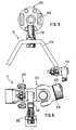
- Das Schwingenlager nach Fig. 3 ist im Prinzip wie das nach Fig. 1 aufgebaut, nur die Befestigung des Spurstangenkopfes 13 erfolgt nicht am Anschlußflansch des Kreuzgelenkes, sondern am Anschlußflansch 212 einer Schaltstange 21, wobei zwischen diesem Anschlußflansch und der Schaltstange noch ein Rohrabschnitt 211 mit einem Durchbruch 219 für die Anordnung des Spurstangenkopfes 13 erforderlich ist. Mit dem Fernschaltbock nach den Figuren 4 und 5 wird in bekannter Weise die Wähl- und Schaltbewegung vom Fahrer über den Schalthebel 36 die am Fahrzeug befestigte Konsole 37 und über eine Gabel 38 auf das in Fig. 6 und 7 dargestellte Schaltgestänge 2 in bekannter Weise-DE-C-21 59 195-übertragen. Erfindungswesentlich ist nur die Übersetzung für die Wählbewegung zwischen dem Dreh- und Schwenkpunkt 32 am kardanischen Gelenk der Konsole 37, dem Mittelpunkt des Gelenkes für das Schalten 330 einerseits mit A bezeichnet und dem Gelenkmittelpunkt für das Schalten 330 sowie dem Abstützpunkt 34 für die Abstützstange 39 andererseits mit B bezeichnet. Der Ansatz 31 mit dem Anschlußflansch 35, der an der Gabel 38 nach Fig. 4 befestigt ist, trägt die Abstützstange 39 und ist deshalb zur Bildung der Übersetzung notwendig.
- Aus Fig. 6 in Ansicht und Fig. 7 in Draufsicht ist die gesamte Fernschaltanlage zwischen dem Fernschaltbock 3 mit dem Schalthebel 41 im Fahrerhaus 4 und dem Getriebe 5 mit der Drehwelle 51 am Heck des Fahrzeuges erkennbar. Mit 6 ist der Fahrzeugrahmen bezeichnet, an dem die Schwingenlager 1 wie auch der Fernschaltbock 3 und das Getriebe 5 befestigt sind. Das Schaltgestänge 2 besteht aus den Schaltstangen 21, wobei die Abstützung am Fahrzeugrahmen 6 über die Schwingenlager 1 nach den Ausführungen Fig. 1 bis 3 z.B. erfolgen können.
- Die Fig. 8 und 9 zeigen eine weitere Ausführung des Schwingenlagers 10, wobei die Lagerschwinge 120 bügelartig gestaltet ist. Sie trägt einen Spurstangenkopf 130, der, wie bereits in Fig. 1 beschrieben, entweder über einen konischen Anschluß oder über eine zylindrische Bohrung-Fig. 8-in einem Teil des Kreuzgelenkes 220 mit diesem zentrisch verbunden ist.
- Die Lagerschwinge 120 ist über zwei weitere Spurstangenköpfe 110 gelenkig am Fahrzeugrahmen befestigt, wobei die Spurstangenköpfe 110 eine begrenzte Schwenkbewegung der Lagerschwinge 120 und damit eine begrenzte Bewegung des Schaltgestänges 2 in axialer Richtung zulassen.
- Eine der Schaltstangen 210 ist mit dem Kreuzgelenk 220 fest, z.B. mit einer Schweißnaht 230, verbunden. Damit hat jede Gelenkstelle-Kreuzgelenk 220-des Schaltgestänges 2 nur eine Flanschverbindung 225.
- In einer weiteren Ausgestaltung nach den Fig. 10 und 11 ist im Bereich der Schaltgestängelagerung 7 die Verbindung des Kreuzgelenkes 71 mit der Schaltstange 72 noch als Ausgleichs- und Klemmeinrichtung 73 ausgebildet, um die axiale Anpassung des Schaltgestänges 2 an den Fahrzeugrahmen 6 und die Zentrierung der Schaltstangen 72 mit den Kreuzgelenken 71 zu vereinfachen. Dazu hat das Gelenkteil 710 im Bereich des angeformten Flansches 712 eine konische Bohrung 711 zur Aufnahme eines geschlitzten konischen Klemmringes 74, und die Befestigungsaugen des Flansches 712 haben Gewindebohrungen 713 zur Aufnahme von Befestigungsschrauben 75. Der zweite Flansch 721 ist nicht mehr mit der Schaltstange 72 fest verbunden, sondern wird mit seiner großen Bohrung 722 bei radialem Spiel über die grob abgelängte Schaltstange gesteckt. Ein geschlitzter konischer Klemmring 74 hat eine zylindrische Bohrung 741 und wird gleichfalls über das abgelängte Ende der Schaltstange gesteckt, so daß der radiale außenliegende Konus 741 beim Anfädeln des Kreuzgelenkes 71 auf die Schaltstange 72 teilweise in der konischen Bohrung 711 des Gelenkteiles 710 zu liegen kommt. Werden nach der Befestigung der Schaltgestängelagerung 7 an den Fahrzeugrahmen 6 die Befestigungsschrauben 75 angezogen, so drückt der zweite Flansche 721 auf die Stirnseite 743 des Klemmringes 74, und das Schaltgestänge wird in der durch die Ausgleichs- und Klemmeinrichtung 73 eingestellten Lage fixiert. Wird der Konus 742 in einem Winkel von etwa 8 bis 9° ausgeführt, können mit dieser Klemmung alle Schaltkräfte in axialer wie auch im Umfangsrichtung übertragen werden.
- Die Fernschaltanlage wirkt wie folgt: Wird z.B. der Schalthebel nach Fig. 4 in Fahrtrichtung (nach links) bewegt, werden die in der Schaltkulisse in Fahrtrichtung liegenden Gänge vorrangig 1, 3, 5, 7 usw. geschaltet. Dabei wird über den Dreh- und Schwenkpunkt 32 die Bewegung umgelenkt, und das Gelenk für das Schalten bewegt sich in Gegenfahrtrichtung, also nach rechts. Damit wird das am Anschlußflansch 35 befestigte Schaltgestänge ebenfalls nach rechts bewegt, wobei alle Schwingenlager 1 aus der gezeichneten Mittelstellung-Fig. 1-um den Bolzen 112 in eine Endlage ca. 17° nach rechts geschwenkt werden. Die Kugellagerung zwischen Lagerbock 11 und Lagerschwinge 12 und die Beweglichkeit des konischen Anschlusses 132 am Spurstangenkopf 13 ermöglicht in Verbindung mit dem Kreuzgelenken 22 eine leichtgängige Verschiebung, die z.B. eine Verdrehung der Drehwelle 51 am Getriebe 5 sicherstellt, wobei die Schaltung der Gänge über die Schaltstangen und Schaltschwingen in bekannter Weise erfolgt.
- Zum Wählen der Gassen wird der Schalthebel nach Fig. 5 aus der Neutrallage quer zur Fahrtrichtung, z.B. nach links, bewegt, so bewegt sich der Punkt 33 infolge der Drehung um den Dreh- und Schwenkpunkt 32 nach rechts. Da der Abstützpunkt 34 infolge der Abstützung durch die Abstützstange 39 fest stehenbleibt, ergibt sich eine Drehbewegung auf das Schaltgestänge 2. Diese Drehbewegung des Schaltgestänges 2 führt zu einer Verschiebebewegung der Drehwelle 51 im Getriebe 5 und damit zum Wählen der Gassen und wird durch die Spurstangenköpfe 13 der Schwingenlager 1 nicht wesentlich behindert.
-
- 1 Schwingenlager
- 10 Schwingenlager
- 11 Lagerbock
- 110 Spurstangenkopf
- 111 Kugel- oder Gleitlager
- 112 Bolzen
- 12 Lagerschwinge
- 120 Lagerschwinge
- 121 Schaft
- 13 Spurstangenkopf
- 130 Spurstangenkopf
- 131 Gewindeteil
- 132 konischer Anschluß
- 133 Kontermutter
- 134 Mutter
- 135 Gewindezapfen
- 2 Schaltgestänge
- 21 Schaltstange
- 210 Schaltstange
- 211 Rohrabschnitt
- 212 Anschlußflansch
- 213 konische Bohrung
- 214 Anschlußflansch
- 215 Anschlußflansch
- 216 Rohr
- 217 konisch verjüngt
- 218 zylindrisch verjüngt
- 22 Kreuzgelenk
- 220 Kreuzgelenk
- 221 Gelenkteil
- 222 Anschlußflansch
- 223 konische Bohrung
- 225 Flanschverbindung
- 226 zweites Gelenkteil
- 227 zweiter Anschlußflansch
- 23 Verbindungsschrauben
- 230 Schweißnaht
- 3 Fernschaltbock
- 31 Ansatz
- 32 Dreh- und Schwerpunkt
- 33 Gelenk für Schalten
- 34 Abstützpunkt
- 35 Anschlußflansch
- 36 Schalthebel
- 37 Konsole
- 38 Gabel
- 39 Abstützstange
- 4 Fahrerhaus
- 41 Schalthebel
- 5 Getriebe
- 51 Drehwelle
- 6 Fahrzeugrahmen
- 7 Schaltgestängelagerung
- 71 Kreuzgelenk
- 710 Gelenkteil
- 711 konische Bohrung
- 712 Flansch
- 713 Gewindebohrung
- 72 Schaltstange
- 721 zweiter Flansch
- 722 große Bohrung
- 73 Ausgleichs- und Klemmeinrichtung
- 74 konischer Klemmring
- 741 zylindrische Bohrung
- 742 Konus
- 743 Stirnseite
- 75 Befestigungsschrauben
Claims (11)
Applications Claiming Priority (2)
| Application Number | Priority Date | Filing Date | Title |
|---|---|---|---|
| WOPCT/EP85/00652 | 1985-11-28 | ||
| EP8500652 | 1985-11-28 |
Publications (2)
| Publication Number | Publication Date |
|---|---|
| EP0284608A1 EP0284608A1 (de) | 1988-10-05 |
| EP0284608B1 true EP0284608B1 (de) | 1990-06-20 |
Family
ID=8165081
Family Applications (1)
| Application Number | Title | Priority Date | Filing Date |
|---|---|---|---|
| EP87900084A Expired - Lifetime EP0284608B1 (de) | 1985-11-28 | 1986-11-21 | Mechanische fernschaltanlage |
Country Status (6)
| Country | Link |
|---|---|
| US (1) | US4848178A (de) |
| EP (1) | EP0284608B1 (de) |
| JP (1) | JPS63502340A (de) |
| BR (1) | BR8607214A (de) |
| DE (2) | DE3672156D1 (de) |
| WO (1) | WO1987003255A1 (de) |
Families Citing this family (3)
| Publication number | Priority date | Publication date | Assignee | Title |
|---|---|---|---|---|
| IT214962Z2 (it) * | 1988-12-27 | 1990-07-30 | Iveco Fiat | Gruppo di rinvio per il comando del cambio di veicoli industriali |
| US7599745B2 (en) * | 2000-02-17 | 2009-10-06 | Standen Ltd | Treating a tumor or the like with an electric field |
| DE102011002762A1 (de) | 2011-01-17 | 2012-07-19 | Bayerische Motoren Werke Aktiengesellschaft | Schaltstrang für eine Einstrangschaltvorrichtung |
Family Cites Families (17)
| Publication number | Priority date | Publication date | Assignee | Title |
|---|---|---|---|---|
| US2137337A (en) * | 1936-07-23 | 1938-11-22 | George A Gemmer | Gear shifting mechanism |
| US2390711A (en) * | 1943-11-26 | 1945-12-11 | Kenworth Motor Truck Corp | Remote control for variable-speed transmission |
| US2669316A (en) * | 1945-11-05 | 1954-02-16 | Gen Motors Corp | Remote-control system for gear shifting in angularly disposed vehicle transmissions |
| US2468316A (en) * | 1947-03-28 | 1949-04-26 | Xpediter Corp | Power-driven hand truck and transmission therefor |
| US2854088A (en) * | 1955-12-07 | 1958-09-30 | Clark Equipment Co | Transmission remote control device for tilt cab vehicles |
| DE2159195C3 (de) * | 1971-11-30 | 1976-01-02 | Zahnradfabrik Friedrichshafen Ag, 7990 Friedrichshafen | Fernschaltbock für Gangschalteinrichtungen von Kraftfahrzeugen |
| GB1390125A (en) * | 1972-03-24 | 1975-04-09 | Itw Ltd | Closures for holes |
| DE2326207A1 (de) * | 1973-05-23 | 1974-12-12 | Daimler Benz Ag | Getriebe-fernschaltung fuer kraftfahrzeuge mit kippbarem fahrerhaus |
| DE2460428C3 (de) * | 1974-12-20 | 1980-01-03 | Daimler-Benz Ag, 7000 Stuttgart | Wasserablauftülle, insbesondere für Hohlräume in Kraftwagenaufbauten |
| JPS5180669A (ja) * | 1975-01-11 | 1976-07-14 | Kokan Giken Kk | Kantannifuranjiokeiseisuruhoho oyobi sochi |
| US3978739A (en) * | 1975-07-23 | 1976-09-07 | Dean Hobbensiefken | Transmission shift control |
| US3978737A (en) * | 1975-08-27 | 1976-09-07 | Xerox Corporation | Chain tensioning device |
| DE2546497C2 (de) * | 1975-10-17 | 1984-08-23 | Daimler-Benz Ag, 7000 Stuttgart | Fernschaltvorrichtung für Kraftfahrzeuge, insbesondere Nutzfahrzeuge |
| GB2006898B (en) * | 1977-09-14 | 1982-03-17 | Hino Motors Ltd | Transmission control device for tilt cab type automobile |
| US4206826A (en) * | 1978-11-20 | 1980-06-10 | International Harvester Company | Transmission remote shift system of the disconnect type for a cab-over chassis |
| JPS5835578U (ja) * | 1981-09-02 | 1983-03-08 | 株式会社城南製作所 | 自動車用ウインドレギユレ−タ |
| SE430399B (sv) * | 1983-02-16 | 1983-11-14 | Saab Scania Ab | Arrangemang for fjerrmanovrering av en vexellada i fordon |
-
1986
- 1986-11-21 JP JP62500400A patent/JPS63502340A/ja active Pending
- 1986-11-21 WO PCT/EP1986/000673 patent/WO1987003255A1/de not_active Ceased
- 1986-11-21 BR BR8607214A patent/BR8607214A/pt not_active IP Right Cessation
- 1986-11-21 DE DE8787900084T patent/DE3672156D1/de not_active Expired - Lifetime
- 1986-11-21 EP EP87900084A patent/EP0284608B1/de not_active Expired - Lifetime
- 1986-11-21 DE DE19863639865 patent/DE3639865A1/de not_active Withdrawn
- 1986-11-21 US US07/085,742 patent/US4848178A/en not_active Expired - Fee Related
Also Published As
| Publication number | Publication date |
|---|---|
| DE3672156D1 (de) | 1990-07-26 |
| DE3639865A1 (de) | 1987-06-04 |
| BR8607214A (pt) | 1988-11-01 |
| JPS63502340A (ja) | 1988-09-08 |
| WO1987003255A1 (fr) | 1987-06-04 |
| US4848178A (en) | 1989-07-18 |
| EP0284608A1 (de) | 1988-10-05 |
Similar Documents
| Publication | Publication Date | Title |
|---|---|---|
| DE3939343C2 (de) | Elektrische Servolenkeinrichtung für Motorfahrzeuge | |
| EP1051577B1 (de) | Schaltvorrichtung für ein zahnräderwechselgetriebe | |
| EP0825367B1 (de) | Betätigungseinrichtung für ein Kraftfahrzeuggetriebe | |
| DE2658274B2 (de) | Lagerung für einen Handschalthebel für Wechselgetriebe von Fahrzeugen | |
| DE102017113708A1 (de) | Radaufhängung für die Hinterachse eines Fahrzeugs | |
| DE2336848C2 (de) | Mechanische Fernschaltvorrichtung für ein Kraftfahrzeugwechselgetriebe | |
| DE3824296C2 (de) | ||
| EP1108166B1 (de) | Schaltvorrichtung für kraftfahrzeug-wechselgetriebe | |
| DE2912787A1 (de) | Radaufhaengung fuer kraftfahrzeuge | |
| EP0936384A1 (de) | Betätigungseinrichtung für ein Fahrzeuggetriebe | |
| DE19544837A1 (de) | Gangschalteinrichtung zur manuellen Betätigung eines mehrgängigen Schaltgetriebes | |
| DE3639865A1 (de) | Mechanische fernschaltanlage | |
| DE19509475C2 (de) | Schaltgestänge-Verbindung | |
| DE3109182C1 (de) | Verbindungselement für Schaltgestänge von Kraftfahrzeugen | |
| DE4101010A1 (de) | Vorrichtung zur uebertragung einer steuer- oder schaltbewegung, insbesondere zum schalten eines kraftfahrzeuggetriebes | |
| DE19532883C2 (de) | Sicherheitslenksäule für ein Kraftfahrzeug | |
| DE602005004679T2 (de) | Verstellbare Kraftfahrzeuglenksäule | |
| DE3934733A1 (de) | Fernschalteinrichtung fuer wechselgetriebe | |
| DE19924238A1 (de) | Schaltvorrichtung für ein Automatikgetriebe eines Kraftfahrzeuges | |
| DE4407540B4 (de) | Steuereinrichtung für ein Getriebe | |
| DE3144348A1 (de) | Zahnstangenlenkung fuer kraftfahrzeuge | |
| DE2508679C2 (de) | Gangschalteinrichtung für Fahrzeuge mit kippbarem Fahrerhaus | |
| EP0441248A1 (de) | Vorrichtung zum Schalten des Getriebes eines Kraftfahrzeuges | |
| EP0803664B1 (de) | Gangschalteinrichtung zur manuellen Betätigung eines mehrgängigen Schaltgetriebes | |
| DE69200236T2 (de) | Mechanische Übertragung zwischen einem Schalthebel und dem Getriebe. |
Legal Events
| Date | Code | Title | Description |
|---|---|---|---|
| PUAI | Public reference made under article 153(3) epc to a published international application that has entered the european phase |
Free format text: ORIGINAL CODE: 0009012 |
|
| 17P | Request for examination filed |
Effective date: 19871120 |
|
| AK | Designated contracting states |
Kind code of ref document: A1 Designated state(s): DE GB |
|
| 17Q | First examination report despatched |
Effective date: 19891128 |
|
| GRAA | (expected) grant |
Free format text: ORIGINAL CODE: 0009210 |
|
| AK | Designated contracting states |
Kind code of ref document: B1 Designated state(s): DE GB |
|
| REF | Corresponds to: |
Ref document number: 3672156 Country of ref document: DE Date of ref document: 19900726 |
|
| GBT | Gb: translation of ep patent filed (gb section 77(6)(a)/1977) | ||
| PGFP | Annual fee paid to national office [announced via postgrant information from national office to epo] |
Ref country code: GB Payment date: 19901024 Year of fee payment: 5 |
|
| PLBE | No opposition filed within time limit |
Free format text: ORIGINAL CODE: 0009261 |
|
| STAA | Information on the status of an ep patent application or granted ep patent |
Free format text: STATUS: NO OPPOSITION FILED WITHIN TIME LIMIT |
|
| 26N | No opposition filed | ||
| PG25 | Lapsed in a contracting state [announced via postgrant information from national office to epo] |
Ref country code: GB Effective date: 19911121 |
|
| GBPC | Gb: european patent ceased through non-payment of renewal fee | ||
| PGFP | Annual fee paid to national office [announced via postgrant information from national office to epo] |
Ref country code: DE Payment date: 20021128 Year of fee payment: 17 |
|
| PG25 | Lapsed in a contracting state [announced via postgrant information from national office to epo] |
Ref country code: DE Free format text: LAPSE BECAUSE OF NON-PAYMENT OF DUE FEES Effective date: 20040602 |