EP0803664B1 - Gangschalteinrichtung zur manuellen Betätigung eines mehrgängigen Schaltgetriebes - Google Patents
Gangschalteinrichtung zur manuellen Betätigung eines mehrgängigen Schaltgetriebes Download PDFInfo
- Publication number
- EP0803664B1 EP0803664B1 EP97103398A EP97103398A EP0803664B1 EP 0803664 B1 EP0803664 B1 EP 0803664B1 EP 97103398 A EP97103398 A EP 97103398A EP 97103398 A EP97103398 A EP 97103398A EP 0803664 B1 EP0803664 B1 EP 0803664B1
- Authority
- EP
- European Patent Office
- Prior art keywords
- gear shift
- bearing housing
- pivoting
- cable
- gear
- Prior art date
- Legal status (The legal status is an assumption and is not a legal conclusion. Google has not performed a legal analysis and makes no representation as to the accuracy of the status listed.)
- Expired - Lifetime
Links
- 230000033001 locomotion Effects 0.000 claims description 51
- 230000005540 biological transmission Effects 0.000 claims description 17
- 238000011161 development Methods 0.000 description 2
- 230000018109 developmental process Effects 0.000 description 2
- 230000036316 preload Effects 0.000 description 2
- 230000002441 reversible effect Effects 0.000 description 2
- 238000010276 construction Methods 0.000 description 1
- 238000013016 damping Methods 0.000 description 1
- 230000001419 dependent effect Effects 0.000 description 1
- 230000005284 excitation Effects 0.000 description 1
- 230000002349 favourable effect Effects 0.000 description 1
- 238000009434 installation Methods 0.000 description 1
- 230000003993 interaction Effects 0.000 description 1
- 238000007665 sagging Methods 0.000 description 1
Images


Classifications
-
- F—MECHANICAL ENGINEERING; LIGHTING; HEATING; WEAPONS; BLASTING
- F16—ENGINEERING ELEMENTS AND UNITS; GENERAL MEASURES FOR PRODUCING AND MAINTAINING EFFECTIVE FUNCTIONING OF MACHINES OR INSTALLATIONS; THERMAL INSULATION IN GENERAL
- F16H—GEARING
- F16H61/00—Control functions within control units of change-speed- or reversing-gearings for conveying rotary motion ; Control of exclusively fluid gearing, friction gearing, gearings with endless flexible members or other particular types of gearing
- F16H61/26—Generation or transmission of movements for final actuating mechanisms
- F16H61/36—Generation or transmission of movements for final actuating mechanisms with at least one movement being transmitted by a cable
-
- F—MECHANICAL ENGINEERING; LIGHTING; HEATING; WEAPONS; BLASTING
- F16—ENGINEERING ELEMENTS AND UNITS; GENERAL MEASURES FOR PRODUCING AND MAINTAINING EFFECTIVE FUNCTIONING OF MACHINES OR INSTALLATIONS; THERMAL INSULATION IN GENERAL
- F16H—GEARING
- F16H59/00—Control inputs to control units of change-speed- or reversing-gearings for conveying rotary motion
- F16H59/02—Selector apparatus
- F16H59/04—Ratio selector apparatus
-
- F—MECHANICAL ENGINEERING; LIGHTING; HEATING; WEAPONS; BLASTING
- F16—ENGINEERING ELEMENTS AND UNITS; GENERAL MEASURES FOR PRODUCING AND MAINTAINING EFFECTIVE FUNCTIONING OF MACHINES OR INSTALLATIONS; THERMAL INSULATION IN GENERAL
- F16H—GEARING
- F16H59/00—Control inputs to control units of change-speed- or reversing-gearings for conveying rotary motion
- F16H59/02—Selector apparatus
- F16H2059/026—Details or special features of the selector casing or lever support
- F16H2059/0269—Ball joints or spherical bearings for supporting the lever
Definitions
- the invention relates to a switching device for manual actuation of a multi-speed manual transmission, preferably a motor vehicle according to the Features of the preamble of claim 1.
- a gear shift device for a manual transmission is for example from the DE - 41 28 161 known. It has a manual shift lever that is used by a driver Choosing a gear in a first direction and shifting in a second direction are moved or pivoted in the first direction running at a right angle can.
- a mechanical power transmission device transmits the movements of the Manual shift lever on the manual transmission or its actuators, as a rule a shifting and rotatable switching shaft about its longitudinal axis.
- the manual transmission, the power transmission device and the manual shift lever are usually designed and aligned in such a way that the manual shift lever initially is pivoted in the transverse direction to the vehicle axis to a specific selection position to reach. Then the hand lever is either in the direction of Vehicle axle swiveled forward or backward, ⁇ m in the desired gear to switch.
- the power transmission device consists of twistable and displaceable shift rods, the lever mechanism on the manual shift lever or on the Switch shaft are coupled.
- EP 0 032 883 A1 also discloses a switching device for a manual transmission is known in which a switching device housing has a ball pin on which a swivel plate connected with a manual shift lever and comprising a ball socket is stored. To prevent the shift lever from rotating about its longitudinal axis is formed in the swivel plate an approximately axially parallel annular groove into which a housing-fixed guide pin protrudes.
- the object of the invention is the latter to further develop generic switching device so that at a cheaper Construction a more precise transmission of the switching movements is achieved.
- the cables of the switching device are in one development of the invention on the one Side connected to the bearing housing by cable adapters and on the other side with cable holders or other fastening elements with the actuator.
- the Rope receptacles or fasteners with which the actuator, e.g. the Control shaft that is pivoted are at the same or different distance from the Pivot axis of the actuator arranged.
- the rope recordings or Fasteners that adjust the actuator in the longitudinal direction can on the positioning axis or at the same or different distance next to it are located.
- the cable holders per pivot axis can be different or the same Have clearances to the pivot axis of the bearing housing.
- the cable holders can for example on an advantageously cylindrical bearing housing be arranged on a plane at a distance of 90 degrees on the swivel axes.
- the cables which are attached to an axle in pairs, can be tensioned by they counteract each other's preload, creating a backlash-free Motion transmission is achieved.
- a single shift rod used for the actuating and Reset movement on tension and pressure is not possible in the art be biased.
- a play-free adjustment creates an exact shift feeling for the driver, which increases comfort.
- Another advantage of the cables is that the operating directions on the hand lever the dialing and shifting movements are easily reversible by the cable pulls be coupled accordingly to the cable holders.
- the manual shift lever is used to select and shift gears by two Swivel axes swiveled.
- the bearing housing which is fixed with the manual shift lever, but possibly also releasably connected, carries out the pivoting movements and forwards them to the cables via the cable holders.
- the swivel axes, on to which the bearing housing is supported can be separated by two crossing axes, e.g. by a universal joint.
- Another advantageous according to the invention Design consists in forming the bearing housing with a ball socket and to store this on a ball stud, thereby saving the two axles and overall fewer components are required.
- the angular positions change due to the pivoting movement of the bearing housing the axes of the cables to the cable mounts.
- the contact surfaces of the ends of the cables are to avoid the resulting tension and the cable receptacles designed so that the ends of the cables are relative to the Rope recordings can move so that the cables are always one to the end Make straight.
- This can be easily achieved by means of cables, the spherical one end up have and are stored in ball-shaped rope receptacles, or the rope receptacles are spherical and the rope end pieces form the spherical shell.
- FIG. 1 shows part of a manual shift lever 1, which has a bearing housing 6 fixed, but possibly also releasable, is connected. On the circumference of the bearing housing 6 four cable holders 7, 8, 9, 10 are firmly attached. In the cable holders 7, 8, 9, 10 are Cables 5 with a spherical or spherical shell-shaped end 27 which connects between the bearing housing 6 and the actuators 16 of a manual transmission produce.
- the bearing housing 6 can be pivoted with a ball socket 18 on a ball pin 19 stored, which is fixed to a switch housing 28, possibly also detachably connected.
- the ball socket 18 is advantageously closed on the side facing away from the cables 5, encloses the ball of the ball pin 19 by more than half and is for assembly conveniently slit. As a result, the bearing housing 6 is always in the Cable pulls 5 forces pressed on the ball pin 19 and achieved an exact guidance.
- the pivoting movement of the bearing housing 6 is on two defined pivot axes 2, 3 limited by a device 20, whereby only pivoting movements in Dialing and switching direction are permitted.
- the device consists of a bolt 22, which is attached to a pivot axis 3 on the circumference of the bearing housing 6 and with its free end 23 is guided in a groove 24.
- the groove 24 extends in the direction of third axis 21 and enables the pivoting movements about the pivot axes 2, 3 by the end of the bolt 23 a rotational movement and a movement in the longitudinal direction can run in the groove 24.
- FIGS 2, 3, 4 provide a functional drawing for the various arrangements of the Rope recordings 7, 8, and 29, 30. These arrangements can be the same for the rope recordings 9, 10 and the transmission-side recordings are applied.
- FIG. 4 shows a third example, in which the distances 11, 12 on the bearing housing 6 and the distances 31, 32 on the actuator 16 are the same size; however, the distances are 11, 12 on the bearing housing 6 larger than the distances 31, 32 on the actuator 16. This there is also a gear ratio not equal to one.
- the movement components 35, 36 on the actuator 16 are larger than that on the bearing housing 6. This arrangement would also be conceivable the other way round.
- the rule should be that the ratio of the distances 12/31 is equal to the ratio 11/32.
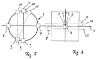
- FIG. 5 shows three possible arrangements of the cable receptacles 7, 8 from the perspective of the z-axis, 9, 10 on the bearing housing 6.
- the selection and switching movement independently of one another when the cable holders 7, 8, 9, 10 are in one plane. This results from the fact that with a pivoting movement a pivot axis 2; 3 each the cable receptacles 7, 8; 9, 10 on the other pivot axis 2; 3 do not experience any deflection since they are on the pivot axis 2; 3 lie.
- the arrangement is, for example, the cable receptacles 9, 10, which are deflected about the pivot axis 3 are arranged parallel to the pivot axis 2.
- the Swivel axis 2 pivoted in the direction of the cable holder 7, so the cable holders 9, 10 with deflected, d. H. in this special case there is an additional tensile stress on the cables 5 in the cable holders 9, 10.
- the cable holder 10 is on the right opposite the pivot axis 2 and the cable receptacle 9 offset to the left relative to the pivot axis 2. There is also one Dependency between selection and switching movement, in which case a cable 5 a greater tension and a cable 5 experiences a low tension.
- FIG. 6 shows, by way of example, that the cable receptacles 7, 8, 9, 10 can also be located in different planes, as a result of which the selection and switching movement is also dependent on one another.
- the examples shown in FIGS. 5 and 6 can each be used in combination and also for both pivot axes.
Landscapes
- Engineering & Computer Science (AREA)
- General Engineering & Computer Science (AREA)
- Mechanical Engineering (AREA)
- Gear-Shifting Mechanisms (AREA)
Description
Es zeigen:
- Fig. 1
- ein Lagergehäuse mit Seilaufnahmen,
- Fig. 2,3,4
- eine Funktionszeichnung zu möglichen Abstandsanordnungen,
- Fig. 5,
- eine schematische Darstellung zu möglichen Anordnungen der Seilaufnahmen am Lagergehäuse aus der Sicht der z-Achse,
- Fig. 6
- eine schematische Darstellung aus der Sicht der y-Achse.
Die in Figur 5 und 6 dargestellten Beispiele können jeweils in Kombination und auch für beide Schwenkachsen angewendet werden.
- 1
- Handschalthebel
- 2
- Schwenkachse
- 3
- Schwenkachse
- 4
- Kraftübertragungseinrichtung
- 5
- Seilzüge
- 6
- Lagergehäuse
- 7
- Seilaufnahme
- 8
- Seilaufnahme
- 9
- Seilaufnahme
- 10
- Seilaufnahme
- 11
- Abstand
- 12
- Abstand
- 15
- Schwenkachse
- 16
- Betätigungsglied
- 17
- Seilrichtung
- 18
- Kugelpfanne
- 19
- Kugelzapfen
- 20
- Vorrichtung
- 21
- Dritte Achse
- 22
- Bolzen
- 23
- Freies Ende des Bolzen
- 24
- Nut
- 25
- Ebene
- 26
- Ebene
- 27
- Ende der Seilzüge
- 28
- Schaltgehäuse
- 29
- Befestigungselement
- 30
- Befestigungselement
- 31
- Abstand
- 32
- Abstand
- 33
- Bewegungskomponente
- 34
- Bewegungskomponente
- 35
- Bewegungskomponente
- 36
- Bewegungskomponente
Claims (7)
- Schalteinrichtung zur manuellen Betätigung eines mehrgängigen Getriebes, mit einem Handschalthebel (1), der zum Wählen von Schaltgassen um eine erste Schwenkachse (3) und zum Schalten von Gängen um eine zweite Schwenkachse (2) schwenkbar ist, und bei der die Schwenkbewegungen des Handschalthebels (1) mittels einer Kraftübertragungseinrichtung (4) auf gangwählende und gangschaltende Betätigungsglieder wie zum Beispiel eine Schaltwelle des Getriebes übertragen werden, wobei die Wähl- und / oder Schaltbewegung durch auf Zug belastete Seilzüge (5) übertragen werden und wobei die Kraftübertragungseinrichtung (4) ein mit dem Handschalthebel (1) fest verbundenes Lagergehäuse (6) aufweist und mindestens zu einer Schwenkachse (2; 3) am Lagergehäuse (6) jeweils zwei Seilaufnahmen (7, 8; 9, 10) zugeordnet sind, die gleiche oder unterschiedliche Abstände (11, 12; 13, 14) von der Schwenkachse (2; 3) aufweisen können, und bei der Stell- und Rückstellbewegung die Seilzüge (5) ständig unter Zugspannung stehen, wobei das Lagergehäuse (6) eine Kugelpfanne (18) aufweist und damit auf einem Kugelzapfen (19) gelagert ist, der fest mit einem Schaltgehäuse (28) verbunden ist, und daß das Lagergehäuse (6) eine Vorrichtung hat, die das Lagergehäuse (6) hindert, sich um eine dritte Achse (21) zu schwenken, dadurch gekennzeichnet, daß die Vorrichtung (20) aus einem Bolzen (22) besteht, der auf einer Schwenkachse (3) außen am Lagergehäuse (6) befestigt ist und mit seinem freien Ende (23) in einer Nut (24) geführt ist, die Schwenkbewegungen zu zwei definierten Schwenkachsen (2; 3) zuläßt.
- Schalteinrichtung nach Anspruch 1, dadurch gekennzeichnet, daß bei Schaltbewegungen eine gleichzeitige Wählbewegung erfolgt oder umgekehrt.
- Schalteinrichtung nach einem der Ansprüche 1 oder 2, dadurch gekennzeichnet, daß die Seilaufnahmen (7, 8, 9, 10) versetzt zu den Schwenkachsen (2, 3) angeordnet sind.
- Schalteinrichtung nach einem der Ansprüche 1 bis 3, dadurch gekennzeichnet, daß die Schwenkachsen (2, 3) nicht senkrecht aufeinander stehen.
- Schalteinrichtung nach einem der Ansprüche 1 bis 4, dadurch gekennzeichnet, daß die Schwenkachsen (2, 3) in unterschiedlichen Ebenen (25, 26) liegen.
- Schalteinrichtung nach einem der oberen Ansprüche, dadurch gekennzeichnet, daß die Seilzüge (5) Enden (27) aufweisen, die winkelig in den Seilaufnahmen (7, 8, 9, 10) auslenkbar sind.
- Schalteinrichtung nach Anspruch 6, dadurch gekennzeichnet, daß die Enden (27) der Seilzüge (5) kugelig sind und diese in kugelschalförmigen Seilaufnahmen (7, 8, 9, 10) am Lagergehäuse (6) gelagert sind oder umgekehrt.
Applications Claiming Priority (2)
| Application Number | Priority Date | Filing Date | Title |
|---|---|---|---|
| DE19617026 | 1996-04-27 | ||
| DE19617026 | 1996-04-27 |
Publications (3)
| Publication Number | Publication Date |
|---|---|
| EP0803664A2 EP0803664A2 (de) | 1997-10-29 |
| EP0803664A3 EP0803664A3 (de) | 1998-11-04 |
| EP0803664B1 true EP0803664B1 (de) | 2002-11-27 |
Family
ID=7792733
Family Applications (1)
| Application Number | Title | Priority Date | Filing Date |
|---|---|---|---|
| EP97103398A Expired - Lifetime EP0803664B1 (de) | 1996-04-27 | 1997-03-01 | Gangschalteinrichtung zur manuellen Betätigung eines mehrgängigen Schaltgetriebes |
Country Status (2)
| Country | Link |
|---|---|
| EP (1) | EP0803664B1 (de) |
| DE (1) | DE59708793D1 (de) |
Families Citing this family (3)
| Publication number | Priority date | Publication date | Assignee | Title |
|---|---|---|---|---|
| DE19740176C2 (de) * | 1997-09-12 | 2000-04-06 | Lemfoerder Metallwaren Ag | Handschaltvorrichtung für ein Kraftfahrzeug |
| DE19821117A1 (de) * | 1998-05-12 | 1999-11-18 | Volkswagen Ag | Vorrichtung zum Anwählen und Schalten zwischen vorgegebenen Positionen |
| CN103851177B (zh) * | 2014-03-31 | 2016-05-11 | 长城汽车股份有限公司 | 选挡换挡组件及具有其的车辆 |
Family Cites Families (5)
| Publication number | Priority date | Publication date | Assignee | Title |
|---|---|---|---|---|
| GB1600821A (en) * | 1978-01-01 | 1981-10-21 | Teleflex Morse Ltd | Remote control mechanisms |
| SE436384B (sv) * | 1980-01-09 | 1984-12-03 | Bergsjo Trima Ab | Manoveranordning for kombinerad paverkan av tva rorliga styrelement |
| US4493224A (en) * | 1982-06-04 | 1985-01-15 | Eaton Corporation | Remote manual shifting mechanism |
| IT8453677U1 (it) * | 1984-07-27 | 1986-01-27 | Fiat Auto Spa | Dispositivo di comando per un cambio di velocita', particolarmente per un autoveicolo |
| BR7401842U (pt) * | 1994-10-19 | 1995-03-21 | Paolo Paparoni | Disposição introduzida em mecanismo de articulação para alavanca de câmbio automotivo com acionamento por cabos. |
-
1997
- 1997-03-01 EP EP97103398A patent/EP0803664B1/de not_active Expired - Lifetime
- 1997-03-01 DE DE59708793T patent/DE59708793D1/de not_active Expired - Fee Related
Also Published As
| Publication number | Publication date |
|---|---|
| DE59708793D1 (de) | 2003-01-09 |
| EP0803664A2 (de) | 1997-10-29 |
| EP0803664A3 (de) | 1998-11-04 |
Similar Documents
| Publication | Publication Date | Title |
|---|---|---|
| EP0825367B1 (de) | Betätigungseinrichtung für ein Kraftfahrzeuggetriebe | |
| DE2658274B2 (de) | Lagerung für einen Handschalthebel für Wechselgetriebe von Fahrzeugen | |
| EP1058034A1 (de) | Schaltvorrichtung für Kraftfahrzeuggetriebe | |
| DE68908925T2 (de) | Fernbetätigungseinrichtung. | |
| DE3824296C2 (de) | ||
| DE19625854A1 (de) | Steuereinrichtung zur Betätigung des Getriebes von Motorfahrzeugen | |
| EP0699853B1 (de) | Betätigungseinrichtung zum Steuern des Gangwechsels eines Kraftfahrzeuggetriebes | |
| DE69300612T2 (de) | Steuervorrichtung für das Geschwindigkeitswechselgetriebe eines Kraftfahrzeuges. | |
| DE19805510A1 (de) | Betätigungseinrichtung für ein Fahrzeuggetriebe | |
| DE19544837A1 (de) | Gangschalteinrichtung zur manuellen Betätigung eines mehrgängigen Schaltgetriebes | |
| DE69304213T2 (de) | Innere Schalteinheit von einem Gangschaltmechanismus | |
| DE102005060933B3 (de) | Wählhebel, insbesondere für ein Kraftfahrzeug | |
| EP0803664B1 (de) | Gangschalteinrichtung zur manuellen Betätigung eines mehrgängigen Schaltgetriebes | |
| DE69602687T2 (de) | Steuerhebelanordnung mit verbesserter Positionsarretierung | |
| DE3839319A1 (de) | Getriebeschaltgeraet fuer kraftfahrzeuge | |
| DE3634174A1 (de) | Vorrichtung zum daempfen von schwingungen in einer getriebeschaltvorrichtung fuer fahrzeuge | |
| DE4004104A1 (de) | Verbindungseinrichtung fuer das schaltgestaenge von kraftfahrzeugen | |
| DE4101010A1 (de) | Vorrichtung zur uebertragung einer steuer- oder schaltbewegung, insbesondere zum schalten eines kraftfahrzeuggetriebes | |
| DE20310055U1 (de) | Handschalthebel für ein Fahrzeuggetriebe | |
| DE69113601T2 (de) | Schaltvorrichtung für ein handgeschaltetes getriebe. | |
| EP1363049B1 (de) | Seilzugschaltung | |
| DE69200236T2 (de) | Mechanische Übertragung zwischen einem Schalthebel und dem Getriebe. | |
| EP0775854A2 (de) | Schaltvorrichtung mit torsionsweichem Tragarm für das Wechselgetriebe in einem Kraftfahrzeug | |
| DE102012002968A1 (de) | Raupenfahrzeug | |
| DE102011087332A1 (de) | Schalthebelanordnung mit Wählübersetzung |
Legal Events
| Date | Code | Title | Description |
|---|---|---|---|
| PUAI | Public reference made under article 153(3) epc to a published international application that has entered the european phase |
Free format text: ORIGINAL CODE: 0009012 |
|
| AK | Designated contracting states |
Kind code of ref document: A2 Designated state(s): DE FR GB IT |
|
| PUAL | Search report despatched |
Free format text: ORIGINAL CODE: 0009013 |
|
| AK | Designated contracting states |
Kind code of ref document: A3 Designated state(s): DE FR GB IT |
|
| 17P | Request for examination filed |
Effective date: 19990504 |
|
| 17Q | First examination report despatched |
Effective date: 20010130 |
|
| GRAG | Despatch of communication of intention to grant |
Free format text: ORIGINAL CODE: EPIDOS AGRA |
|
| GRAG | Despatch of communication of intention to grant |
Free format text: ORIGINAL CODE: EPIDOS AGRA |
|
| GRAH | Despatch of communication of intention to grant a patent |
Free format text: ORIGINAL CODE: EPIDOS IGRA |
|
| GRAH | Despatch of communication of intention to grant a patent |
Free format text: ORIGINAL CODE: EPIDOS IGRA |
|
| GRAA | (expected) grant |
Free format text: ORIGINAL CODE: 0009210 |
|
| AK | Designated contracting states |
Kind code of ref document: B1 Designated state(s): DE FR GB IT |
|
| PG25 | Lapsed in a contracting state [announced via postgrant information from national office to epo] |
Ref country code: GB Free format text: LAPSE BECAUSE OF FAILURE TO SUBMIT A TRANSLATION OF THE DESCRIPTION OR TO PAY THE FEE WITHIN THE PRESCRIBED TIME-LIMIT Effective date: 20021127 |
|
| REG | Reference to a national code |
Ref country code: GB Ref legal event code: FG4D Free format text: NOT ENGLISH |
|
| REF | Corresponds to: |
Ref document number: 59708793 Country of ref document: DE Date of ref document: 20030109 |
|
| GBV | Gb: ep patent (uk) treated as always having been void in accordance with gb section 77(7)/1977 [no translation filed] |
Effective date: 20021127 |
|
| ET | Fr: translation filed | ||
| PLBE | No opposition filed within time limit |
Free format text: ORIGINAL CODE: 0009261 |
|
| STAA | Information on the status of an ep patent application or granted ep patent |
Free format text: STATUS: NO OPPOSITION FILED WITHIN TIME LIMIT |
|
| 26N | No opposition filed |
Effective date: 20030828 |
|
| PGFP | Annual fee paid to national office [announced via postgrant information from national office to epo] |
Ref country code: FR Payment date: 20050318 Year of fee payment: 9 |
|
| REG | Reference to a national code |
Ref country code: FR Ref legal event code: ST Effective date: 20061130 |
|
| PG25 | Lapsed in a contracting state [announced via postgrant information from national office to epo] |
Ref country code: FR Free format text: LAPSE BECAUSE OF NON-PAYMENT OF DUE FEES Effective date: 20060331 |
|
| PGFP | Annual fee paid to national office [announced via postgrant information from national office to epo] |
Ref country code: IT Payment date: 20090318 Year of fee payment: 13 Ref country code: DE Payment date: 20090331 Year of fee payment: 13 |
|
| PG25 | Lapsed in a contracting state [announced via postgrant information from national office to epo] |
Ref country code: DE Free format text: LAPSE BECAUSE OF NON-PAYMENT OF DUE FEES Effective date: 20101001 |
|
| PG25 | Lapsed in a contracting state [announced via postgrant information from national office to epo] |
Ref country code: IT Free format text: LAPSE BECAUSE OF NON-PAYMENT OF DUE FEES Effective date: 20100301 |