EP0803664B1 - Gear shift device for manual control of a multi-speed gearbox - Google Patents
Gear shift device for manual control of a multi-speed gearbox Download PDFInfo
- Publication number
- EP0803664B1 EP0803664B1 EP97103398A EP97103398A EP0803664B1 EP 0803664 B1 EP0803664 B1 EP 0803664B1 EP 97103398 A EP97103398 A EP 97103398A EP 97103398 A EP97103398 A EP 97103398A EP 0803664 B1 EP0803664 B1 EP 0803664B1
- Authority
- EP
- European Patent Office
- Prior art keywords
- gear shift
- bearing housing
- pivoting
- cable
- gear
- Prior art date
- Legal status (The legal status is an assumption and is not a legal conclusion. Google has not performed a legal analysis and makes no representation as to the accuracy of the status listed.)
- Expired - Lifetime
Links
Images


Classifications
-
- F—MECHANICAL ENGINEERING; LIGHTING; HEATING; WEAPONS; BLASTING
- F16—ENGINEERING ELEMENTS AND UNITS; GENERAL MEASURES FOR PRODUCING AND MAINTAINING EFFECTIVE FUNCTIONING OF MACHINES OR INSTALLATIONS; THERMAL INSULATION IN GENERAL
- F16H—GEARING
- F16H61/00—Control functions within control units of change-speed- or reversing-gearings for conveying rotary motion ; Control of exclusively fluid gearing, friction gearing, gearings with endless flexible members or other particular types of gearing
- F16H61/26—Generation or transmission of movements for final actuating mechanisms
- F16H61/36—Generation or transmission of movements for final actuating mechanisms with at least one movement being transmitted by a cable
-
- F—MECHANICAL ENGINEERING; LIGHTING; HEATING; WEAPONS; BLASTING
- F16—ENGINEERING ELEMENTS AND UNITS; GENERAL MEASURES FOR PRODUCING AND MAINTAINING EFFECTIVE FUNCTIONING OF MACHINES OR INSTALLATIONS; THERMAL INSULATION IN GENERAL
- F16H—GEARING
- F16H59/00—Control inputs to control units of change-speed-, or reversing-gearings for conveying rotary motion
- F16H59/02—Selector apparatus
- F16H59/04—Ratio selector apparatus
-
- F—MECHANICAL ENGINEERING; LIGHTING; HEATING; WEAPONS; BLASTING
- F16—ENGINEERING ELEMENTS AND UNITS; GENERAL MEASURES FOR PRODUCING AND MAINTAINING EFFECTIVE FUNCTIONING OF MACHINES OR INSTALLATIONS; THERMAL INSULATION IN GENERAL
- F16H—GEARING
- F16H59/00—Control inputs to control units of change-speed-, or reversing-gearings for conveying rotary motion
- F16H59/02—Selector apparatus
- F16H2059/026—Details or special features of the selector casing or lever support
- F16H2059/0269—Ball joints or spherical bearings for supporting the lever
Definitions
- the invention relates to a switching device for manual actuation of a multi-speed manual transmission, preferably a motor vehicle according to the Features of the preamble of claim 1.
- a gear shift device for a manual transmission is for example from the DE - 41 28 161 known. It has a manual shift lever that is used by a driver Choosing a gear in a first direction and shifting in a second direction are moved or pivoted in the first direction running at a right angle can.
- a mechanical power transmission device transmits the movements of the Manual shift lever on the manual transmission or its actuators, as a rule a shifting and rotatable switching shaft about its longitudinal axis.
- the manual transmission, the power transmission device and the manual shift lever are usually designed and aligned in such a way that the manual shift lever initially is pivoted in the transverse direction to the vehicle axis to a specific selection position to reach. Then the hand lever is either in the direction of Vehicle axle swiveled forward or backward, ⁇ m in the desired gear to switch.
- the power transmission device consists of twistable and displaceable shift rods, the lever mechanism on the manual shift lever or on the Switch shaft are coupled.
- EP 0 032 883 A1 also discloses a switching device for a manual transmission is known in which a switching device housing has a ball pin on which a swivel plate connected with a manual shift lever and comprising a ball socket is stored. To prevent the shift lever from rotating about its longitudinal axis is formed in the swivel plate an approximately axially parallel annular groove into which a housing-fixed guide pin protrudes.
- the object of the invention is the latter to further develop generic switching device so that at a cheaper Construction a more precise transmission of the switching movements is achieved.
- the cables of the switching device are in one development of the invention on the one Side connected to the bearing housing by cable adapters and on the other side with cable holders or other fastening elements with the actuator.
- the Rope receptacles or fasteners with which the actuator, e.g. the Control shaft that is pivoted are at the same or different distance from the Pivot axis of the actuator arranged.
- the rope recordings or Fasteners that adjust the actuator in the longitudinal direction can on the positioning axis or at the same or different distance next to it are located.
- the cable holders per pivot axis can be different or the same Have clearances to the pivot axis of the bearing housing.
- the cable holders can for example on an advantageously cylindrical bearing housing be arranged on a plane at a distance of 90 degrees on the swivel axes.
- the cables which are attached to an axle in pairs, can be tensioned by they counteract each other's preload, creating a backlash-free Motion transmission is achieved.
- a single shift rod used for the actuating and Reset movement on tension and pressure is not possible in the art be biased.
- a play-free adjustment creates an exact shift feeling for the driver, which increases comfort.
- Another advantage of the cables is that the operating directions on the hand lever the dialing and shifting movements are easily reversible by the cable pulls be coupled accordingly to the cable holders.
- the manual shift lever is used to select and shift gears by two Swivel axes swiveled.
- the bearing housing which is fixed with the manual shift lever, but possibly also releasably connected, carries out the pivoting movements and forwards them to the cables via the cable holders.
- the swivel axes, on to which the bearing housing is supported can be separated by two crossing axes, e.g. by a universal joint.
- Another advantageous according to the invention Design consists in forming the bearing housing with a ball socket and to store this on a ball stud, thereby saving the two axles and overall fewer components are required.
- the angular positions change due to the pivoting movement of the bearing housing the axes of the cables to the cable mounts.
- the contact surfaces of the ends of the cables are to avoid the resulting tension and the cable receptacles designed so that the ends of the cables are relative to the Rope recordings can move so that the cables are always one to the end Make straight.
- This can be easily achieved by means of cables, the spherical one end up have and are stored in ball-shaped rope receptacles, or the rope receptacles are spherical and the rope end pieces form the spherical shell.
- FIG. 1 shows part of a manual shift lever 1, which has a bearing housing 6 fixed, but possibly also releasable, is connected. On the circumference of the bearing housing 6 four cable holders 7, 8, 9, 10 are firmly attached. In the cable holders 7, 8, 9, 10 are Cables 5 with a spherical or spherical shell-shaped end 27 which connects between the bearing housing 6 and the actuators 16 of a manual transmission produce.
- the bearing housing 6 can be pivoted with a ball socket 18 on a ball pin 19 stored, which is fixed to a switch housing 28, possibly also detachably connected.
- the ball socket 18 is advantageously closed on the side facing away from the cables 5, encloses the ball of the ball pin 19 by more than half and is for assembly conveniently slit. As a result, the bearing housing 6 is always in the Cable pulls 5 forces pressed on the ball pin 19 and achieved an exact guidance.
- the pivoting movement of the bearing housing 6 is on two defined pivot axes 2, 3 limited by a device 20, whereby only pivoting movements in Dialing and switching direction are permitted.
- the device consists of a bolt 22, which is attached to a pivot axis 3 on the circumference of the bearing housing 6 and with its free end 23 is guided in a groove 24.
- the groove 24 extends in the direction of third axis 21 and enables the pivoting movements about the pivot axes 2, 3 by the end of the bolt 23 a rotational movement and a movement in the longitudinal direction can run in the groove 24.
- FIGS 2, 3, 4 provide a functional drawing for the various arrangements of the Rope recordings 7, 8, and 29, 30. These arrangements can be the same for the rope recordings 9, 10 and the transmission-side recordings are applied.
- FIG. 4 shows a third example, in which the distances 11, 12 on the bearing housing 6 and the distances 31, 32 on the actuator 16 are the same size; however, the distances are 11, 12 on the bearing housing 6 larger than the distances 31, 32 on the actuator 16. This there is also a gear ratio not equal to one.
- the movement components 35, 36 on the actuator 16 are larger than that on the bearing housing 6. This arrangement would also be conceivable the other way round.
- the rule should be that the ratio of the distances 12/31 is equal to the ratio 11/32.
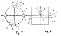
- FIG. 5 shows three possible arrangements of the cable receptacles 7, 8 from the perspective of the z-axis, 9, 10 on the bearing housing 6.
- the selection and switching movement independently of one another when the cable holders 7, 8, 9, 10 are in one plane. This results from the fact that with a pivoting movement a pivot axis 2; 3 each the cable receptacles 7, 8; 9, 10 on the other pivot axis 2; 3 do not experience any deflection since they are on the pivot axis 2; 3 lie.
- the arrangement is, for example, the cable receptacles 9, 10, which are deflected about the pivot axis 3 are arranged parallel to the pivot axis 2.
- the Swivel axis 2 pivoted in the direction of the cable holder 7, so the cable holders 9, 10 with deflected, d. H. in this special case there is an additional tensile stress on the cables 5 in the cable holders 9, 10.
- the cable holder 10 is on the right opposite the pivot axis 2 and the cable receptacle 9 offset to the left relative to the pivot axis 2. There is also one Dependency between selection and switching movement, in which case a cable 5 a greater tension and a cable 5 experiences a low tension.
- FIG. 6 shows, by way of example, that the cable receptacles 7, 8, 9, 10 can also be located in different planes, as a result of which the selection and switching movement is also dependent on one another.
- the examples shown in FIGS. 5 and 6 can each be used in combination and also for both pivot axes.
Description
Die Erfindung betrifft eine Schalteinrichtung zur manuellen Betätigung eines mehrgängigen Schaltgetriebes, vorzugsweise eines Kraftfahrzeuges gemäß den Merkmalen des Oberbegriff des Patentanspruchs 1.The invention relates to a switching device for manual actuation of a multi-speed manual transmission, preferably a motor vehicle according to the Features of the preamble of claim 1.
Eine Gangschalteinrichtung für ein Schaltgetriebe ist beispielsweise aus der DE - 41 28 161 bekannt. Sie besitzt einen Handschalthebel der von einem Fahrer zum Wählen eines Getriebeganges in eine erste Richtung und zum Schalten in eine zweite, zur ersten unter einem rechten Winkel verlaufende Richtung bewegt bzw. geschwenkt werden kann. Eine mechanische Kraftübertragungseinrichtung überträgt die Bewegungen des Handschalthebels auf das Schaltgetriebe bzw. dessen Betätigungsglieder, im Regelfall eine verschiebbare sowie um ihre Längsachse verdrehbare Schaltwelle.A gear shift device for a manual transmission is for example from the DE - 41 28 161 known. It has a manual shift lever that is used by a driver Choosing a gear in a first direction and shifting in a second direction are moved or pivoted in the first direction running at a right angle can. A mechanical power transmission device transmits the movements of the Manual shift lever on the manual transmission or its actuators, as a rule a shifting and rotatable switching shaft about its longitudinal axis.
Das Schaltgetriebe, die Kraftübertragungseinrichtung und der Handschalthebel sind üblicherweise in der Art ausgebildet und ausgerichtet, daß der Handschalthebel zunächst in Querrichtung zur Fahrzeugachse verschwenkt wird, um eine bestimmte Wählposition zu erreichen. Anschließend wird der Handschalthebel entweder in Richtung der Fahrzeugachse nach vorne oder nach hinten verschwenkt, µm in den gewünschten Gang zu schalten.The manual transmission, the power transmission device and the manual shift lever are usually designed and aligned in such a way that the manual shift lever initially is pivoted in the transverse direction to the vehicle axis to a specific selection position to reach. Then the hand lever is either in the direction of Vehicle axle swiveled forward or backward, µm in the desired gear to switch.
Die Kraftübertragungseinrichtung besteht aus verdreh- und verschiebbaren Schaltstangen, die über einen vielfach gelagerten Hebelmechanismus am Handschalthebel bzw. an der Schaltwelle angekoppelt sind.The power transmission device consists of twistable and displaceable shift rods, the lever mechanism on the manual shift lever or on the Switch shaft are coupled.
Diese Kraftübertragungseinrichtungen neigen dazu, Aggregatschwingungen und bewegungen zu dem Handschalthebel weiterzuleiten, was von dem Fahrer eines solchen Fahrzeuges als unkomfortabel empfunden wird, unerwünschte Geräusche erzeugt und einen zusätzlichen Aufwand an Dämpfungsmitteln erfordert. Bei sehr starken Aggregatschwingungen bzw. -bewegungen können die Gänge sogar herausspringen. Der Schaltkomfort erfordert es, daß der Handschalthebel in einer bequemen Reichweite des Fahrers im Fahrzeug angeordnet ist; anderseits richtet sich die Lage des Getriebes nach den Einbaumöglichkeiten des Antriebsstranges im Fahrzeug. Deshalb muß die Kraftübertragungseinrichtung häufig einen erheblichen Abstand überbrücken und einen Versatz in den Bewegungsrichtungen ausgleichen. Dadurch werden die bekannten Schalteinrichtungen sehr komplex. Die häufig erforderliche große Anzahl der Lagerstellen ergibt zwangsläufig viel Spiel, welches das Schaltgefühl ebenfalls beeinträchtigt (unexaktes Schaltgefühl).These power transmission devices tend to vibrate and aggregate to forward movements to the manual shift lever, what the driver of such Vehicle is perceived as uncomfortable, generates unwanted noise and requires an additional effort on damping agents. With very strong ones Unit vibrations or movements can even jump out of the gears. The Shift comfort requires that the manual shift lever be within easy reach of the Driver is arranged in the vehicle; on the other hand, the position of the gearbox depends on the installation options for the drive train in the vehicle. Therefore, the Power transmission device often bridge a considerable distance and one Compensate for misalignment in the directions of movement. This will make the known Switching devices very complex. The often required large number of bearings results in a lot of play, which also affects the shift feeling (inexact shift feeling).
Außerdem ist aus der EP 0 032 883 A1 eine Schalteinrichtung für ein Handschaltgetriebe bekannt, bei der ein Schalteinrichtungsgehäuse einen Kugelzapfen aufweist, auf dem eine mit einem Handschalthebel verbundene und eine Kugelpfanne umfassende Schwenkplatte gelagert ist. Zur Vermeidung einer Drehbewegung des Schalthebels um seine Längsachse ist in der Schwenkplatte eine in etwa achsparallel ausgerichtete Ringnut ausgebildet, in die ein gehäusefester Führungsstift hineinragt.EP 0 032 883 A1 also discloses a switching device for a manual transmission is known in which a switching device housing has a ball pin on which a swivel plate connected with a manual shift lever and comprising a ball socket is stored. To prevent the shift lever from rotating about its longitudinal axis is formed in the swivel plate an approximately axially parallel annular groove into which a housing-fixed guide pin protrudes.
Vor diesem Hintergrund besteht die Aufgabe der Erfindung darin, die letztgenannte gattungsbildende Schalteinrichtung so weiterzubilden, daß bei einer preisgünstigeren Konstruktion eine exaktere Übertragung der Schaltbewegungen erreicht wird.Against this background, the object of the invention is the latter to further develop generic switching device so that at a cheaper Construction a more precise transmission of the switching movements is achieved.
Die Aufgabe wird durch die Merkmale des Anspruchs 1 gelöst, während vorteilhafte Ausgestaltungen und Weiterbildungen der Erfindung den Unteransprüchen entnehmbar sind.The object is solved by the features of claim 1, while advantageous Refinements and developments of the invention can be found in the subclaims are.
Erfindungsgemäß umfaßt die gegenüber dem Stand der Technik weitergebildete Schalteinrichtung zur Verhinderung einer Schwenk- oder Drehbewegung des Lagergehäuses um dessen Längsachse "Z" einen Bolzen, der auf einer Schwenkachse außen am Lagergehäuse befestigt ist und mit seinem freien Ende in einer Nut geführt ist, die Schwenkbewegungen zu den zwei definierten Schwenkachsen "X, Y" zuläßt.According to the invention, the further developed compared to the prior art Switching device to prevent a pivoting or rotating movement of the Bearing housing about its longitudinal axis "Z" a bolt on a pivot axis is attached to the outside of the bearing housing and is guided with its free end in a groove, allows the swiveling movements to the two defined swiveling axes "X, Y".
Die Seilzüge der Schaltvorrichtung sind in einer Weiterbildung der Erfindung auf der einen Seite durch Seilaufnahmen mit dem Lagergehäuse verbunden und auf der anderen Seite mit Seilaufnahmen oder sonstigen Befestigungselementen mit dem Betätigungsglied. Die Seilaufnahmen oder Befestigungselemente, mit denen das Betätigungsglied, z.B. die Schaltwelle, geschwenkt wird, sind mit gleichem oder unterschiedlichem Abstand von der Schwenkachse des Betätigungsgliedes angeordnet. Die Seilaufnahmen oder Befestigungselemente, die das Betätigungsglied in Längsrichtung verstellen, können sich auf der Stellachse oder auch in gleichem oder unterschiedlichem Abstand daneben befinden. The cables of the switching device are in one development of the invention on the one Side connected to the bearing housing by cable adapters and on the other side with cable holders or other fastening elements with the actuator. The Rope receptacles or fasteners with which the actuator, e.g. the Control shaft that is pivoted are at the same or different distance from the Pivot axis of the actuator arranged. The rope recordings or Fasteners that adjust the actuator in the longitudinal direction can on the positioning axis or at the same or different distance next to it are located.
In Abhängigkeit von den Abständen der Seilaufnahmen oder Befestigungselemente des Betätigungsglied zu dessen Schwenk- oder Stellachse und von der gewünschten Übersetzung, können die Seilaufnahmen pro Schwenkachse unterschiedliche oder gleiche Abstände zu der Schwenkachse des Lagergehäuses aufweisen.Depending on the distances between the cable holders or fastening elements of the Actuator to its swivel or actuating axis and from the desired one Gear ratio, the cable holders per pivot axis can be different or the same Have clearances to the pivot axis of the bearing housing.
Entscheidend ist, daß ein in sich bewegbares System entsteht, daß sich nicht in seiner Bewegung selbst hemmt und daß die Seilzüge ständig unter Zugspannung stehen, d. h. in keiner Schwenkstellung durchhängen, wodurch ein präzises, ruckfreies Schalten nicht mehr möglich wäre.It is crucial that a system that can move is created, that it does not move inhibits itself and that the cables are constantly under tension, d. H. in no sagging, which prevents precise, jerk-free shifting would be more possible.
Bei der Übertragung der Schalt- und der Wählbewegung durch Seilzüge, können die Seilaufnahmen beispielsweise an einem vorteilhaft zylindrisch ausgebildeten Lagergehäuse auf einer Ebene im Abstand von 90 Grad auf den Schwenkachsen angeordnet sein.When transmitting the switching and the selection movement by means of cables, the cable holders can for example on an advantageously cylindrical bearing housing be arranged on a plane at a distance of 90 degrees on the swivel axes.
Die an einer Achse paarweise angebrachten Seilzüge können verspannt werden, indem sie gegenseitig der Vorspannung entgegenwirken, wodurch eine spielfreie Bewegungsübertragung erreicht wird. Eine einzelne Schaltstange, die für die Stell- und Rückstellbewegung auf Zug und Druck belastet wird, kann dagegen nicht in der Art vorgespannt werden.The cables, which are attached to an axle in pairs, can be tensioned by they counteract each other's preload, creating a backlash-free Motion transmission is achieved. A single shift rod used for the actuating and Reset movement on tension and pressure is not possible in the art be biased.
Durch eine spielfreie Einstellung wird beim Fahrer ein exaktes Schaltgefühl geschaffen, wodurch der Komfort erhöht wird.A play-free adjustment creates an exact shift feeling for the driver, which increases comfort.
Mit Seilzügen können bei geringem Gewicht große Abstände überbrückt und mit einfachen Seilführungen Versatz ausgeglichen und schwierige räumliche Verhältnisse gemeistert werden.With cables, large distances can be bridged with light weight and with simple ones Rope guides compensate for misalignment and overcome difficult spatial conditions become.
Ebenfalls positiv auf den Komfort wirkt sich aus, daß die elastischen und biegsamen Seilzüge die Aggregateschwingungen und -bewegungen ausgleichen, und die Schwingungskomponenten in alle Richtungen vom Handschalthebel entkoppelt werden. Insgesamt zeigen Seilzüge gegenüber Schaltstangen, insbesondere wegen ihrer geringen Masse, in Bezug auf Schwingungserregung und -weiterleitung, ein günstigeres Verhalten. Also positive for comfort is that the elastic and pliable Cable pulls to compensate for the vibrations and movements of the unit, and the Vibration components can be decoupled from the manual shift lever in all directions. Overall, cable pulls show shift rods, especially because of their low Mass, in terms of vibration excitation and transmission, a more favorable behavior.
Ein weiterer Vorteil der Seilzüge ist, daß die Betätigungsrichtungen am Handschalthebel der Wähl- und Schaltbewegungen einfach umkehrbar sind, indem die Seilzüge entsprechend an den Seilaufnahmen angekoppelt werden.Another advantage of the cables is that the operating directions on the hand lever the dialing and shifting movements are easily reversible by the cable pulls be coupled accordingly to the cable holders.
Besonders vorteilhaft ist, daß die Seilenden direkt an dem schwenkbaren Lagergehäuse befestigt sind und durch dessen Schwenkbewegungen ausgelenkt werden, wodurch die Anzahl der Lager und bewegten Teile sowie das Spiel und die Reibung minimiert und die Leichtgängigkeit gefordert wird. Weniger Bauteile bedeuten zudem einen Kostenvorteil und eine einfachere Montage.It is particularly advantageous that the rope ends directly on the pivotable bearing housing are attached and deflected by its pivoting movements, thereby the Number of bearings and moving parts as well as the play and friction minimized and the Ease of movement is required. Fewer components also mean a cost advantage and easier assembly.
Der Handschalthebel wird zum Wählen und Schalten von Gängen um zwei Schwenkachsen geschwenkt. Das Lagergehäuse, das mit dem Handschalthebel fest, möglicherweise jedoch auch lösbar verbunden ist, führt die Schwenkbewegungen mit aus und leitet diese über die Seilaufnahmen auf die Seilzüge weiter. Die Schwenkachsen, auf denen das Lagergehäuse gelagert wird, können durch zwei sich kreuzende Achsen, z.B. durch ein Kardangelenk, gebildet werden. Eine weitere erfindungsgemäße vorteilhafte Ausgestaltung besteht darin, das Lagergehäuse mit einer Kugelpfanne auszubilden und dieses auf einem Kugelzapfen zu lagern, wodurch die beiden Achsen eingespart und insgesamt weniger Bauteile benötigt werden.The manual shift lever is used to select and shift gears by two Swivel axes swiveled. The bearing housing, which is fixed with the manual shift lever, but possibly also releasably connected, carries out the pivoting movements and forwards them to the cables via the cable holders. The swivel axes, on to which the bearing housing is supported can be separated by two crossing axes, e.g. by a universal joint. Another advantageous according to the invention Design consists in forming the bearing housing with a ball socket and to store this on a ball stud, thereby saving the two axles and overall fewer components are required.
Durch Seilaufnahmen, die versetzt zu den Schwenkachsen am Lagergehäuse angebracht sind, wird erreicht, daß die Wähl- und die Schaltbewegung voneinander abhängen. Dies wird zudem erreicht, wenn die Schwenkachsen nicht senkrecht aufeinander stehen. Ist das Lagergehäuse nicht auf einem Kugelzapfen, sondern auf zwei getrennten Achsen gelagert, so kann eine Abhängigkeit der Wähl- und Schaltbewegung erreicht werden, indem sich die Achsen in unterschiedlichen Ebenen befinden.By means of cable holders that are offset to the swivel axes on the bearing housing are achieved, that the selection and the switching movement depend on each other. This is also achieved if the swivel axes are not perpendicular to each other. Is this Bearing housing not on a ball stud, but on two separate axes stored, a dependence of the selection and switching movement can be achieved by the axes are in different planes.
Durch die Schwenkbewegung des Lagergehäuses verändern sich die Winkelstellungen der Achsen der Seilzüge zu den Seilaufnahmen. Um hierdurch in den Seilaufnahmen entstehende Spannungen zu vermeiden, sind die Kontaktflächen der Enden der Seilzüge und der Seilaufnahmen so gestaltet, daß sich die Enden der Seilzüge relativ zu den Seilaufnahmen bewegen können, so daß stets die Seilzüge bis zu ihrem Ende eine Gerade bilden. Dies kann konstruktiv einfach durch Seilzüge erreicht werden, die kugelige Enden aufweisen und in kugelschalförmigen Seilaufnahmen gelagert sind, oder die Seilaufnahmen sind kugelig und die Seilendstücke bilden die Kugelschale.The angular positions change due to the pivoting movement of the bearing housing the axes of the cables to the cable mounts. To do this in the rope recordings The contact surfaces of the ends of the cables are to avoid the resulting tension and the cable receptacles designed so that the ends of the cables are relative to the Rope recordings can move so that the cables are always one to the end Make straight. This can be easily achieved by means of cables, the spherical one end up have and are stored in ball-shaped rope receptacles, or the rope receptacles are spherical and the rope end pieces form the spherical shell.
Indem unterschiedlichen Wählpositionen unterschiedliche Schaltbewegungen zugeordnet sind, d. h. die Wähl- und Schaltbewegung gegenseitig voneinander abhängen, wird eine zusätzliche Vorspannung, dadurch ein geringes Spiel und damit ein exaktes Schaltgefühl beim Fahrer erreicht. Der Fahrer kann leichter an der Art der Schaltbewegung - erforderliche Kraft, Länge der Bewegung und Richtung - erkennen auf welcher Wähl- oder Schaltposition er sich befindet.Assigning different switching movements to different selection positions are, d. H. the selection and switching movement depend on each other, an additional Preload, resulting in little play and thus an exact shift feeling when Driver reached. The driver can easier on the type of shift movement - required Force, length of movement and direction - recognize at which selection or switching position he is.
In der Zeichnung sind Ausführungsbeispiele der Erfindung dargestellt.Exemplary embodiments of the invention are shown in the drawing.
In der Beschreibung und in den Ansprüchen sind zahlreiche Merkmale im Zusammenhang dargestellt und beschrieben.Numerous features are related in the description and claims shown and described.
Der Fachmann wird die Merkmale zweckmäßigerweise auch einzeln betrachten und zu sinnvollen
Kombinationen zusammenfassen.
Es zeigen:
- Fig. 1
- ein Lagergehäuse mit Seilaufnahmen,
- Fig. 2,3,4
- eine Funktionszeichnung zu möglichen Abstandsanordnungen,
- Fig. 5,
- eine schematische Darstellung zu möglichen Anordnungen der Seilaufnahmen am Lagergehäuse aus der Sicht der z-Achse,
- Fig. 6
- eine schematische Darstellung aus der Sicht der y-Achse.
Show it:
- Fig. 1
- a bearing housing with cable holders,
- Fig. 2,3,4
- a functional drawing of possible spacing arrangements,
- Fig. 5,
- a schematic representation of possible arrangements of the cable receptacles on the bearing housing from the perspective of the z-axis,
- Fig. 6
- a schematic representation from the perspective of the y-axis.
In Figur 1 ist ein Teil eines Handschalthebels 1 dargestellt, der mit einem Lagergehäuse 6
fest, jedoch möglicherweise auch lösbar, verbunden ist. Am Umfang des Lagergehäuses 6
sind vier Seilaufnahmen 7, 8, 9, 10 fest angebracht. In den Seilaufnahmen 7, 8, 9, 10 sind
Seilzüge 5 mit einem kugeligen oder kugelschalenförmigen Ende 27 gelagert, die eine Verbindung
zwischen dem Lagergehäuse 6 und den Betätigungsgliedem 16 eines Schaltgetriebes
herstellen.FIG. 1 shows part of a manual shift lever 1, which has a bearing
Das Lagergehäuse 6 ist mit einer Kugelpfanne 18 auf einem Kugelzapfen 19 schwenkbar
gelagert, der fest mit einem Schaltgehäuse 28, möglicherweise auch lösbar, verbunden ist.
Die Kugelpfanne 18 ist vorteilhaft auf der den Seilzügen 5 abgewandten Seite geschlossen,
umschließt die Kugel des Kugelzapfens 19 um mehr als die Hälfte und ist zur Montage
zweckmäßigerweise aufgeschlitzt. Dadurch wird das Lagergehäuse 6 stets durch die in den
Seilzügen 5 wirkenden Kräfte auf den Kugelzapfen 19 gepreßt und eine exakte Führung erreicht.The bearing
Die Schwenkbewegung des Lagergehäuses 6 ist auf zwei definierte Schwenkachsen 2, 3
durch eine Vorrichtung 20 beschränkt, wodurch ausschließlich Schwenkbewegungen in
Wähl- und Schaltrichtung zugelassen werden. Die Vorrichtung besteht aus einem Bolzen 22,
der auf einer Schwenkachse 3 am Umfang der Lagergehäuses 6 angebracht ist und mit seinem
freien Ende 23 in einer Nut 24 geführt wird. Die Nut 24 erstreckt sich in Richtung der
dritten Achse 21 und ermöglicht die Schwenkbewegungen um die Schwenkachsen 2, 3, indem
das Ende des Bolzens 23 eine Rotationsbewegung und eine Bewegung in Längsrichtung
in der Nut 24 ausführen kann.The pivoting movement of the bearing
Durch die Schwenkbewegung des Handschalthebels 1 und damit auch des mit diesem fest
verbunden Lagergehäuses 6, werden die Enden 27 der Seilzüge 5 ausgelenkt, wodurch
über die Seilzüge 5 eine Stellbewegung, die Wähl- oder Schaltbewegung, an die Betätigungsglieder
16, in der Regel die Schaltwelle, übertragen werden.By the pivoting movement of the manual control lever 1 and thus also with it
connected bearing
Die Figuren 2, 3, 4 stellen eine Funktionszeichnung zu den verschiedenen Anordnungen der
Seilaufnahmen 7, 8, und 29, 30 dar. Diese Anordnungen können genau so für die Seilaufnahmen
9, 10 und die getriebeseitigen Aufnahmen angewendet werden.Figures 2, 3, 4 provide a functional drawing for the various arrangements of the
Da von Seilzügen nur Zugkräfte übertragen werden können, sind pro Schwenkachse 2, 3
zwei Seilzüge 5 erforderlich, um eine Stell- und Rückstellkraft zu erzeugen. Die Seele dieser
Seilzüge kann auch einteilig sein. Um durch eine Schwenkbewegung des Handschalthebels
1 z. B. eine Auslenkung der Seilaufnahmen 7, 8 am Lagergehäuse 6 zu erreichen und durch
eine Auslenkung der Seilaufnahmen bzw. Befestigungselemente 29, 30 am Betätigungsglied
16 eine Schwenkbewegung zu erzeugen, müssen die Seilaufnahmen 7, 8, 29, 30 einen Abstand
11, 12, 13, 14; 31, 32 von der Schwenkachse 2, 3; 15 aufweisen. Von dem Zusammenwirken
dieser Abstände 11, 12, 31, 32 und deren Orientierung zum Drehpunkt, ist zum
einen die Bewegungsfreiheit und zum anderen das erreichte Übersetzungsverhältnis abhängig.Since cable pulls can only transmit tensile forces, there are 2, 3 per swivel axis
two
In Figur 2 sind alle Abstände 11, 12, 31, 32 gleich und die Schwenkachsen 2, 15 befinden
sich in der Mitte zwischen den Seilaufnahmen 7, 8; 29, 30. Dies stellt ein konstruktiv sehr
einfache Lösung dar, bei der die Bewegungskomponenten 33, 34, 35, 36 alle gleich groß
sind, d. h. es entsteht keine Übersetzung. In Figure 2, all distances 11, 12, 31, 32 are the same and the pivot axes 2, 15 are located
itself in the middle between the
In Figur 3 dagegen sind nur jeweils die gegenüberliegenden Abstände 12, 31; 11, 32 gleich.
Hierdurch entstehen auf der Seite der kleineren Abstände 12, 31 kleinere Bewegungskomponenten
33, 35 wie auf der Seite der größeren Abstände 11, 32. Es entsteht ein
Übersetzungsverhältnis ungleich eins. Durch ein Übersetzungsverhältnis kann man die Kraft
und die Wege am Handschalthebel optimieren. Zudem können durch derartige Anordnungen
Platzprobleme gelöst werden.In contrast, in Figure 3 only the
Figur 4 stellt ein drittes Beispiel dar, bei welchem die Abstände 11, 12 am Lagergehäuse 6
und die Abstände 31, 32 am Betätigungsglied 16 gleich groß sind; jedoch sind die Abstände
11, 12 am Lagergehäuse 6 größer als die Abstände 31, 32 am Betätigungsglied 16. Hierdurch
entsteht ebenfalls ein Übersetzungsverhältnis ungleich eins. Die Bewegungskomponenten
35, 36 am Betätigungsglied 16 sind größer als die am Lagergehäuse 6. Diese Anordnung
wäre auch umgekehrt denkbar.FIG. 4 shows a third example, in which the
Für die einwandfreie Funktion ist ein Regelfall anzustreben, daß das Verhältnis der Abstände
12/31 gleich dem Verhältnis 11/32 ist.In order for the system to function properly, the rule should be that the ratio of the
Figur 5 zeigt aus der Sicht der z-Achse drei mögliche Anordnungen der Seilaufnahmen 7, 8,
9, 10 am Lagergehäuse 6. In der ersten Anordnung befinden sich die Seilaufnahmen 7, 8, 9,
10 auf den Schwenkachsen 2, 3 des Lagergehäuses 6. Bei einer derartigen Anordnung sind
die Wähl- und Schaltbewegung unabhängig voneinander, wenn sich die Seilaufnahmen 7, 8,
9, 10 in einer Ebene befinden. Dies ergibt sich daraus, daß bei einer Schwenkbewegung um
eine Schwenkachse 2; 3 jeweils die Seilaufnahmen 7, 8; 9, 10 auf der anderen Schwenkachse
2; 3 keine Auslenkung erfahren, da sie auf der Schwenkachse 2; 3 liegen.FIG. 5 shows three possible arrangements of the
Demgegenüber entsteht eine Abhängigkeit der Wähl- und Schaltbewegung bei den nächsten
zwei Anordnungen, die beispielhaft mit gestrichelten Linien dargestellt sind. Bei der zweiten
Anordnung sind beispielhaft die Seilaufnahmen 9, 10, die um die Schwenkachse 3 ausgelenkt
werden, parallel neben der Schwenkachse 2 angeordnet. Wird beispielsweise um die
Schwenkachse 2 in Richtung der Seilaufnahme 7 geschwenkt, so werden die Seilaufnahmen
9, 10 mit ausgelenkt, d. h. es entsteht in diesem speziellen Fall eine zusätzliche Zugspannung
auf die Seilzüge 5 in den Seilaufnahmen 9, 10.In contrast, there is a dependence of the selection and switching movement in the next
two arrangements, which are shown by way of example with dashed lines. The second
The arrangement is, for example, the
In der dritten Anordnung ist die Seilaufnahme 10 rechts gegenüber der Schwenkachse 2 und
die Seilaufnahme 9 links gegenüber der Schwenkachse 2 versetzt. Es besteht ebenfalls eine
Abhängigkeit zwischen Wähl- und Schaltbewegung, wobei in diesem Fall ein Seilzug 5 eine
größerer Zugspannung und ein Seilzug 5 eine geringe Zugspannung erfährt. In the third arrangement, the
Grundsätzlich sinnvoll erscheint es, die Wählpositionen, 1 Gang, 2 Gang, 3 Gang, 4 Gang, 5
Gang, Rückwärtsgang, sowie die Schaltpositionen 1 Gang, 2 Gang; 3 Gang, 4 Gang; 5
Gang um einen Umkehrpunkt, d. h. um 0, 90, 180, 270 oder 360 Grad um eine Schwenkachse
2; 3 anzuordnen, wodurch große Auslenkungen erreicht werden.Basically it makes sense to choose positions, 1 gear, 2 gear, 3 gear, 4 gear, 5
Gear, reverse gear and the shift positions 1 gear, 2 gear; 3 gear, 4 gear; 5
Walk around a reversal point, i.e. H. by 0, 90, 180, 270 or 360 degrees around a
In Figur 6 ist beispielhaft dargestellt, daß sich die Seilaufnahmen 7, 8, 9, 10 auch in unterschiedlichen
Ebenen befinden können, wodurch ebenfalls eine Abhängigkeit der Wähl- und
Schaltbewegung voneinander erreicht wird.
Die in Figur 5 und 6 dargestellten Beispiele können jeweils in Kombination und auch für
beide Schwenkachsen angewendet werden. FIG. 6 shows, by way of example, that the
The examples shown in FIGS. 5 and 6 can each be used in combination and also for both pivot axes.
- 11
- Handschalthebelmanual shift
- 22
- Schwenkachseswivel axis
- 33
- Schwenkachseswivel axis
- 44
- KraftübertragungseinrichtungPower transmission device
- 55
- Seilzügecables
- 66
- Lagergehäusebearing housing
- 77
- Seilaufnahmecable receptacle
- 88th
- Seilaufnahmecable receptacle
- 99
- Seilaufnahmecable receptacle
- 1010
- Seilaufnahmecable receptacle
- 1111
- Abstanddistance
- 1212
- Abstanddistance
- 1515
- Schwenkachseswivel axis
- 1616
- Betätigungsgliedactuator
- 1717
- Seilrichtungcable direction
- 1818
- Kugelpfanneball socket
- 1919
- Kugelzapfenball pin
- 2020
- Vorrichtungcontraption
- 2121
- Dritte AchseThird axis
- 2222
- Bolzenbolt
- 2323
- Freies Ende des BolzenFree end of the bolt
- 2424
- Nutgroove
- 2525
- Ebenelevel
- 2626
- Ebenelevel
- 2727
- Ende der SeilzügeEnd of the cables
- 2828
- Schaltgehäuseswitch housing
- 2929
- Befestigungselementfastener
- 3030
- Befestigungselementfastener
- 3131
- Abstanddistance
- 3232
- Abstand distance
- 3333
- Bewegungskomponentemovement component
- 3434
- Bewegungskomponentemovement component
- 3535
- Bewegungskomponentemovement component
- 3636
- Bewegungskomponentemovement component
Claims (7)
- Gear shift device for manual actuation of a multispeed gearbox, with a manual shift lever (1), which can be pivoted about a first pivoting axis (3) to choose gear shift slots and can be pivoted about a second pivoting axis (2) to shift gears, and in which the pivoting motions of the manual shift lever (1) are transmitted by means of a force transmission device (4) to gear-choosing and gear-shifting actuating members such as, for example, a gear shift shaft of the gearbox, the choosing and/or shift motion being transmitted by cable controls (5) subjected to tension, and the force transmission device (4) having a bearing housing (6) firmly connected to the manual shift lever (1), and two cable holders (7, 8; 9, 10), which can be at the same distance or at different distances (11, 12; 13, 14) from the pivoting axis (2; 3) being assigned in each case at least to one pivoting axis (2; 3) on the bearing housing (6), and the cable controls (5) being continuously under tensile stress during the actuating and return motion, the bearing housing (6) having a ball socket (18) and thereby being supported on a ball pivot (19), which is firmly connected to a gear shift housing (28), and in that the bearing housing (6) has an apparatus (20) which prevents the bearing housing (6) from pivoting about a third axis (21), characterized in that the apparatus (20) comprises a pin (22), which is secured on the pivoting axis (3) on the outside of the bearing housing (6) and is guided by its free end (23) in a slot (24) that permits pivoting motions relative to two defined pivoting axes (2; 3).
- Gear shift device according to Claim 1, characterized in that during gear shift motions there is a simultaneous choosing motion or vice versa.
- Gear shift device according to either of Claims 1 and 2, characterized in that the cable holders (7, 8, 9, 10) are arranged offset relative to the pivoting axes (2, 3).
- Gear shift device according to one of Claims 1 to 3, characterized in that the pivoting axes (2, 3) are not perpendicular to one another.
- Gear shift device according to one of Claims 1 to 4, characterized in that the pivoting axes (2, 3) are in different planes (25, 26).
- Gear shift device according to one of the above claims, characterized in that the cable controls (5) have ends (27) that can be subjected to angular deflection in the cable holders (7, 8, 9, 10).
- Gear shift device according to Claim 6, characterized in that the ends (27) of the cable controls (5) are spherical and these are supported in cable holders (7, 8, 9, 10) in the form of spherical shells on the bearing housing (6) or vice versa.
Applications Claiming Priority (2)
| Application Number | Priority Date | Filing Date | Title |
|---|---|---|---|
| DE19617026 | 1996-04-27 | ||
| DE19617026 | 1996-04-27 |
Publications (3)
| Publication Number | Publication Date |
|---|---|
| EP0803664A2 EP0803664A2 (en) | 1997-10-29 |
| EP0803664A3 EP0803664A3 (en) | 1998-11-04 |
| EP0803664B1 true EP0803664B1 (en) | 2002-11-27 |
Family
ID=7792733
Family Applications (1)
| Application Number | Title | Priority Date | Filing Date |
|---|---|---|---|
| EP97103398A Expired - Lifetime EP0803664B1 (en) | 1996-04-27 | 1997-03-01 | Gear shift device for manual control of a multi-speed gearbox |
Country Status (2)
| Country | Link |
|---|---|
| EP (1) | EP0803664B1 (en) |
| DE (1) | DE59708793D1 (en) |
Families Citing this family (3)
| Publication number | Priority date | Publication date | Assignee | Title |
|---|---|---|---|---|
| DE19740176C2 (en) * | 1997-09-12 | 2000-04-06 | Lemfoerder Metallwaren Ag | Manual switching device for a motor vehicle |
| DE19821117A1 (en) * | 1998-05-12 | 1999-11-18 | Volkswagen Ag | Device for selecting and switching between predetermined positions |
| CN103851177B (en) * | 2014-03-31 | 2016-05-11 | 长城汽车股份有限公司 | Block selecting gearshift assembly and there is its vehicle |
Family Cites Families (5)
| Publication number | Priority date | Publication date | Assignee | Title |
|---|---|---|---|---|
| GB1600821A (en) * | 1978-01-01 | 1981-10-21 | Teleflex Morse Ltd | Remote control mechanisms |
| SE436384B (en) * | 1980-01-09 | 1984-12-03 | Bergsjo Trima Ab | MANUAL DEVICE FOR COMBINED POWER OPERATION OF TWO SPIRITUAL CONTROLS |
| US4493224A (en) * | 1982-06-04 | 1985-01-15 | Eaton Corporation | Remote manual shifting mechanism |
| IT8453677V0 (en) * | 1984-07-27 | 1984-07-27 | Fiat Auto Spa | COMMAND DEVICE FOR A CHANGE OF SPEED, PARTICULARLY FOR A VEHICLE |
| BR7401842U (en) * | 1994-10-19 | 1995-03-21 | Paolo Paparoni | Arrangement introduced in articulation mechanism for automotive gear lever with cable drive. |
-
1997
- 1997-03-01 DE DE59708793T patent/DE59708793D1/en not_active Expired - Fee Related
- 1997-03-01 EP EP97103398A patent/EP0803664B1/en not_active Expired - Lifetime
Also Published As
| Publication number | Publication date |
|---|---|
| DE59708793D1 (en) | 2003-01-09 |
| EP0803664A2 (en) | 1997-10-29 |
| EP0803664A3 (en) | 1998-11-04 |
Similar Documents
| Publication | Publication Date | Title |
|---|---|---|
| DE2658274C3 (en) | Bearing for a manual shift lever for change gears of vehicles | |
| EP1558862B1 (en) | Shifting device for transmitting shifting commands to an automatic gearbox | |
| EP0825367B1 (en) | Actuating mechanis for automatic transmission | |
| DE3824296C2 (en) | ||
| DE102005060933B3 (en) | Gear selector lever e.g. shift-by-wire lever, for e.g. commercial vehicle, has haptic unit formed by pressure unit, gear wheels, motor and/or damper and producing force path of lever, where unit is fixedly arranged with respect to housing | |
| DE19625854A1 (en) | Motor vehicle transmission actuating control with triple structure cable | |
| EP0699853B1 (en) | Mechanism for transmitting movement of vehicle gear selector | |
| DE69905573T2 (en) | DEVICE FOR MANEUVERING | |
| DE19805510A1 (en) | Actuator for a vehicle transmission | |
| DE19544837A1 (en) | Gear shift for manual operation of multiple gear, with gear shift lever | |
| EP0803664B1 (en) | Gear shift device for manual control of a multi-speed gearbox | |
| DE3839319A1 (en) | Gear shift device for motor vehicles | |
| DE3634174A1 (en) | DEVICE FOR DAMPING VIBRATIONS IN A GEAR SHIFTING DEVICE FOR VEHICLES | |
| DE4004104A1 (en) | CONNECTING DEVICE FOR THE SWITCH ROD OF MOTOR VEHICLES | |
| DE4101010A1 (en) | DEVICE FOR TRANSMITTING A CONTROL OR SWITCHING MOVEMENT, IN PARTICULAR FOR SWITCHING A MOTOR VEHICLE TRANSMISSION | |
| EP0681124A2 (en) | Device for damping vibrations in a vehicular transmission gear change device | |
| EP1363049B1 (en) | Shifting device with cable | |
| DE3002968C2 (en) | Actuating device for speed change transmissions of motor vehicles | |
| DE102012002968A1 (en) | Crawler vehicle e.g. combine harvester has control lever that is provided for controlling intermediate speed of speed controllable drive units and degree of displacement in speed difference between speed controllable drive units | |
| DE112004001134B4 (en) | lever assembly | |
| EP0775854A2 (en) | Gear shift mechanism for vehicle transmission, incorporating torsion bar | |
| DE102011087332A1 (en) | Shift lever arrangement for vehicle, has actuating element that is provided for pivotal movement of shift lever at specific angle for selecting shift track, and for pivotal movement of actuating rod around specific angle | |
| DE102011051125A1 (en) | Suspension device of motor vehicle, has hand lever whose switching movement is transmitted to locking rod of power train along two movement directions | |
| EP0467879B1 (en) | Transmission for a tractor with a gear shifting device | |
| EP0810392B1 (en) | Control device |
Legal Events
| Date | Code | Title | Description |
|---|---|---|---|
| PUAI | Public reference made under article 153(3) epc to a published international application that has entered the european phase |
Free format text: ORIGINAL CODE: 0009012 |
|
| AK | Designated contracting states |
Kind code of ref document: A2 Designated state(s): DE FR GB IT |
|
| PUAL | Search report despatched |
Free format text: ORIGINAL CODE: 0009013 |
|
| AK | Designated contracting states |
Kind code of ref document: A3 Designated state(s): DE FR GB IT |
|
| 17P | Request for examination filed |
Effective date: 19990504 |
|
| 17Q | First examination report despatched |
Effective date: 20010130 |
|
| GRAG | Despatch of communication of intention to grant |
Free format text: ORIGINAL CODE: EPIDOS AGRA |
|
| GRAG | Despatch of communication of intention to grant |
Free format text: ORIGINAL CODE: EPIDOS AGRA |
|
| GRAH | Despatch of communication of intention to grant a patent |
Free format text: ORIGINAL CODE: EPIDOS IGRA |
|
| GRAH | Despatch of communication of intention to grant a patent |
Free format text: ORIGINAL CODE: EPIDOS IGRA |
|
| GRAA | (expected) grant |
Free format text: ORIGINAL CODE: 0009210 |
|
| AK | Designated contracting states |
Kind code of ref document: B1 Designated state(s): DE FR GB IT |
|
| PG25 | Lapsed in a contracting state [announced via postgrant information from national office to epo] |
Ref country code: GB Free format text: LAPSE BECAUSE OF FAILURE TO SUBMIT A TRANSLATION OF THE DESCRIPTION OR TO PAY THE FEE WITHIN THE PRESCRIBED TIME-LIMIT Effective date: 20021127 |
|
| REG | Reference to a national code |
Ref country code: GB Ref legal event code: FG4D Free format text: NOT ENGLISH |
|
| REF | Corresponds to: |
Ref document number: 59708793 Country of ref document: DE Date of ref document: 20030109 |
|
| GBV | Gb: ep patent (uk) treated as always having been void in accordance with gb section 77(7)/1977 [no translation filed] |
Effective date: 20021127 |
|
| ET | Fr: translation filed | ||
| PLBE | No opposition filed within time limit |
Free format text: ORIGINAL CODE: 0009261 |
|
| STAA | Information on the status of an ep patent application or granted ep patent |
Free format text: STATUS: NO OPPOSITION FILED WITHIN TIME LIMIT |
|
| 26N | No opposition filed |
Effective date: 20030828 |
|
| PGFP | Annual fee paid to national office [announced via postgrant information from national office to epo] |
Ref country code: FR Payment date: 20050318 Year of fee payment: 9 |
|
| REG | Reference to a national code |
Ref country code: FR Ref legal event code: ST Effective date: 20061130 |
|
| PG25 | Lapsed in a contracting state [announced via postgrant information from national office to epo] |
Ref country code: FR Free format text: LAPSE BECAUSE OF NON-PAYMENT OF DUE FEES Effective date: 20060331 |
|
| PGFP | Annual fee paid to national office [announced via postgrant information from national office to epo] |
Ref country code: IT Payment date: 20090318 Year of fee payment: 13 Ref country code: DE Payment date: 20090331 Year of fee payment: 13 |
|
| PG25 | Lapsed in a contracting state [announced via postgrant information from national office to epo] |
Ref country code: DE Free format text: LAPSE BECAUSE OF NON-PAYMENT OF DUE FEES Effective date: 20101001 |
|
| PG25 | Lapsed in a contracting state [announced via postgrant information from national office to epo] |
Ref country code: IT Free format text: LAPSE BECAUSE OF NON-PAYMENT OF DUE FEES Effective date: 20100301 |