EP0284121A1 - Verfahren zum Behandeln zweier beladener Waschlösungsströme - Google Patents
Verfahren zum Behandeln zweier beladener Waschlösungsströme Download PDFInfo
- Publication number
- EP0284121A1 EP0284121A1 EP88200314A EP88200314A EP0284121A1 EP 0284121 A1 EP0284121 A1 EP 0284121A1 EP 88200314 A EP88200314 A EP 88200314A EP 88200314 A EP88200314 A EP 88200314A EP 0284121 A1 EP0284121 A1 EP 0284121A1
- Authority
- EP
- European Patent Office
- Prior art keywords
- gas
- zone
- relaxation
- expansion
- washing
- Prior art date
- Legal status (The legal status is an assumption and is not a legal conclusion. Google has not performed a legal analysis and makes no representation as to the accuracy of the status listed.)
- Granted
Links
Images

Classifications
-
- B—PERFORMING OPERATIONS; TRANSPORTING
- B01—PHYSICAL OR CHEMICAL PROCESSES OR APPARATUS IN GENERAL
- B01D—SEPARATION
- B01D53/00—Separation of gases or vapours; Recovering vapours of volatile solvents from gases; Chemical or biological purification of waste gases, e.g. engine exhaust gases, smoke, fumes, flue gases, aerosols
- B01D53/14—Separation of gases or vapours; Recovering vapours of volatile solvents from gases; Chemical or biological purification of waste gases, e.g. engine exhaust gases, smoke, fumes, flue gases, aerosols by absorption
- B01D53/1425—Regeneration of liquid absorbents
-
- C—CHEMISTRY; METALLURGY
- C10—PETROLEUM, GAS OR COKE INDUSTRIES; TECHNICAL GASES CONTAINING CARBON MONOXIDE; FUELS; LUBRICANTS; PEAT
- C10K—PURIFYING OR MODIFYING THE CHEMICAL COMPOSITION OF COMBUSTIBLE GASES CONTAINING CARBON MONOXIDE
- C10K1/00—Purifying combustible gases containing carbon monoxide
- C10K1/08—Purifying combustible gases containing carbon monoxide by washing with liquids; Reviving the used wash liquors
- C10K1/16—Purifying combustible gases containing carbon monoxide by washing with liquids; Reviving the used wash liquors with non-aqueous liquids
-
- Y—GENERAL TAGGING OF NEW TECHNOLOGICAL DEVELOPMENTS; GENERAL TAGGING OF CROSS-SECTIONAL TECHNOLOGIES SPANNING OVER SEVERAL SECTIONS OF THE IPC; TECHNICAL SUBJECTS COVERED BY FORMER USPC CROSS-REFERENCE ART COLLECTIONS [XRACs] AND DIGESTS
- Y02—TECHNOLOGIES OR APPLICATIONS FOR MITIGATION OR ADAPTATION AGAINST CLIMATE CHANGE
- Y02C—CAPTURE, STORAGE, SEQUESTRATION OR DISPOSAL OF GREENHOUSE GASES [GHG]
- Y02C20/00—Capture or disposal of greenhouse gases
- Y02C20/40—Capture or disposal of greenhouse gases of CO2
-
- Y—GENERAL TAGGING OF NEW TECHNOLOGICAL DEVELOPMENTS; GENERAL TAGGING OF CROSS-SECTIONAL TECHNOLOGIES SPANNING OVER SEVERAL SECTIONS OF THE IPC; TECHNICAL SUBJECTS COVERED BY FORMER USPC CROSS-REFERENCE ART COLLECTIONS [XRACs] AND DIGESTS
- Y02—TECHNOLOGIES OR APPLICATIONS FOR MITIGATION OR ADAPTATION AGAINST CLIMATE CHANGE
- Y02P—CLIMATE CHANGE MITIGATION TECHNOLOGIES IN THE PRODUCTION OR PROCESSING OF GOODS
- Y02P20/00—Technologies relating to chemical industry
- Y02P20/151—Reduction of greenhouse gas [GHG] emissions, e.g. CO2
Definitions
- the invention relates to a method for treating two scrubbing solution streams which come from different gas washing zones and have absorbed carbon dioxide and pressurized carbon monoxide, hydrogen or melthane there at pressures of 10 to 100 bar.
- the scrubbing solution In gas scrubbing, the scrubbing solution not only absorbs impurities but also certain amounts of valuable gases, the main components of the gas to be scrubbed.
- the object of the invention is therefore to recover these valuable gases as completely as possible from the scrubbing solution streams coming from the gas scrubbing zones.
- this is done by relaxing the first wash solution stream into a first relaxation zone with a pressure reduction of at least 5 bar and thereby releasing a CO2-rich relaxation gas by having the second Wash solution stream partially expanded into a second expansion zone containing mass transfer elements, that the expansion gas is passed from the first expansion zone in countercurrent to the second stream of wash solution through the second expansion zone, at the top of the second expansion zone a CO2 and gas mixture containing at least one valuable gas is withdrawn, and that the both washing solution flows regenerated from the relaxation zones.
- the method of the invention is used particularly when the two wash solution streams that come from the gas washes contain CO2 in different concentrations.
- a high CO2 content of the loaded first washing solution leads in the first relaxation zone to the fact that with the released CO2 a high proportion of the value gases carried into the relaxation gas also passes.
- the expansion gas from the first relaxation zone causes a strong stripping effect, through which the valuable gases are driven out of the second washing solution.
- a very substantial part of the CO2 contained in the expansion gas of the first expansion zone is absorbed again in the second expansion zone in the desired manner.
- the gas mixture drawn off at the top of the second expansion zone is therefore rich in the valuable gases which are recovered by introducing the gas mixture into one of the gas washing zones.
- This recovery of the valuable gases is also advantageous for the regeneration of the wash solution streams, since the valuable gases would otherwise appear to be disruptive in the regeneration exhaust gases.
- the extracted gas mixture can also be used for other purposes, for example as heating gas.
- the two relaxation zones can also be arranged one above the other and the second washing solution stream flowing out of the second zone can be introduced into the first zone.
- the pressure in the two relaxation zones is approximately 5 to 25 bar.
- the first gas scrubbing zone abandoned first gas can differ from the second gas scrubbing zone abandoned gas at least in terms of CO2 content.
- the CO2 content in the first gas is usually at least 1.5 times as high as in the second gas.
- the CO2 content of the first gas is approximately in the range from 20 to 40% by volume and the CO2 content of the second gas is approximately 2 to 15% by volume.
- the first gas comes e.g. a converted water gas in question and the second gas can be an unconverted water gas.
- the first and second gases can also be synthesis gases or gases rich in methane.
- the known physically active solvents in particular methanol and NMP, are used for the two gas washes.
- the temperatures in the wash zones range from + 60 ° C to -80 ° C.
- the first gas washing zone (1) is fed through line (2) to the first gas to be cleaned, which may have a relatively high CO2 content. Regenerated washing solution comes from line (3) and the cleaned gas is drawn off in line (4). The first stream of washing solution leaves the first gas washing zone (1) in line (5).
- the second gas is fed into line (8) of the second gas washing zone (9), which is fed through washing line regenerated through line (10). The washed second gas leaves the second gas washing zone (9) through line (11) and the loaded second gas washing stream is removed in line (12).
- the first gas in line (2) contains in most cases at least 1.5 times as much CO2 as the second gas in line (8).
- the two gas washing zones (1) and (9) in order to intensify the gas-liquid mass exchange, there are known trays or packing elements which are not shown for the sake of simplicity.
- the first stream of washing solution in line (5) is passed into the first relaxation zone (15), where its pressure is reduced by at least 5 bar.
- the relaxation zone (15) can be designed as an empty container.
- the expansion gas of the first expansion zone (15) is led in line (16) to the second expansion zone (17), which contains mass transfer elements (18).
- the second expansion zone (17) which contains mass transfer elements (18).
- the pressures in the two relaxation zones (15) and (17) are usually approximately the same, they are in the range from 5 to 25 bar.
- the two washing solution flows of the relaxation zones (15) and (17) are fed through lines (23) and (24) to a conventional regeneration (25).
- the loads of the washing solutions are removed by at least one of the measures of relaxation, stripping or heating; Regenerated washing solution is returned in lines (3) and (10) for reuse already described.
- a first and a second gas are washed with methanol in the two gas washing zones (1) and (9) at about 37 bar.
- the composition of the two gases is as follows:
- the first wash zone (1) 66 m3 and the second wash zone (9) 81 m3 wash solution are added per hour.
- the wash solution flows in the lines (5, 12, 23, 24) carry the following total loads per hour, with H2 and CO being valuable gases:
- the pressure in the two relaxation zones is around 11 bar.
- column A The gases specified in column A in the table below can be found in the return gas line (21).
- column B gives the sum of the gas quantities in lines (16) and (21) if the expansion gas in line (16) was not passed into the second expansion zone (17) but kept separate:
Abstract
Description
- Die Erfindung betrifft ein Verfahren zum Behandeln zweier Waschlösungsströme, die aus verschiedenen Gaswaschzonen kommen und dort bei Drücken von 10 bis 100 bar durch physikalisches Lösen Kohlendioxid sowie mindestens eines der Wertgase Kohlenmonoxid, Wasserstoff oder Melthan aufgenommen haben.
- Die Reinigung von Gasen durch physikalisch wirkende Waschlösungen, insbesondere die Entfernung von H₂S und CO₂ aus diesen Gasen, ist seit langem bekannt. Verfahren dieser Art sind im deutschen Patent 1 494 806 und in den US-Patenten 3 531 917 und 3 710 546 beschrieben. Ebenfalls bekannt ist, die beladene Waschlösung durch Entspannen, Erhitzen oder Strippen sowie auch durch eine Kombination dieser Maßnahmen zu regenerieren. Als physikalisch wirkende Waschlösungen kommen z.B. Methanol oder N-Methyl-Pyrrolidon (NMP) in Frage. Die Gaswäschen arbeiten üblicherweise im Temperaturbereich von +60°C bis -80°C.
- Bei der Gaswäsche nimmt die Waschlösung nicht nur Verunreinigungen sondern auch gewisse Mengen an Wertgasen, den Hauptkomponenten des zu waschendem Gases, auf. Der Erfindung liegt deshalb die Aufgabe zugrunde, diese Wertgase aus den aus den Gaswaschzonen kommenden Waschlösungsströmen möglichst vollständig wieder zurückzugewinnen. Erfindungsgemäß geschieht dies dadurch, daß man den ersten Waschlösungsstrom in eine erste Entspannungszone hinein mit einer Druckverminderung von mindestens 5 bar entspannt und dabei ein CO₂-reiches Entspannungsgas freisetzt, daß man den zweiten Waschlösungsstrom in eine Stoffaustauschelemente enthaltende zweite Entspannungszone hinein teilweise entspannt, daß man das Entspannungsgas aus der ersten Entspannungszone im Gegenstrom zum zweiten Waschlösungsstrom aufwärts durch die zweite Entspannungszone leitet, am Kopf der zweiten Entspannungszone ein CO₂ und mindestens ein Wertgas enthaltendes Gasgemisch abzeieht, und daß man die beiden Waschlösungsströme aus den Entspannungszonen regeneriert.
- Das Verfahren der Erfindung findet vor allem dann Anwendung, wenn die beiden Waschlösungsströme, die aus den Gaswäscen kommen, CO₂ in unterschiedlicher Konzentration enthalten. Ein hoher CO₂-Gehalt der beladenen ersten Waschlösung führt in der ersten Entspannungszone dazu, daß dort mit dem freigesetzten CO₂ auch ein hoher Anteil der Anteil der mitgeführten Wertgase in das Entspannungsgas übergeht. In der zweiten Entspannungzone, wo der CO₂-ärmere zweite Waschlösungsstrom selbst nur relativ wenig CO₂ einbringt, bewirkt das Entspannungsgas aus der ersten Entspannungszone einen starken Strippeffekt, durch den die Wertgase aus der zweiten Waschlösung ausgetrieben werden. Gleichzeitig wird in erwünschter Weise ein ganz erheblicher Teil des im Entspannungsgas der ersten Entspannungszone ethaltenen CO₂ in der zweiten Entspannungszone wieder absorbiert. Das am Kopf der zweiten Entspannungszone abgezogene Gasgemisch ist dadurch reich an den Wertgfasen, die man durch Einleiten des Gasgemisches in eine der Gaswaschzonen zurückgewinnt. Dieses Zurückgewinnen der Wertgase ist auch für die Regenerierung der Waschlösungsströme vorteilhaft, da die Wertgase ansonsten in den Regenerationsabgasen störend erscheinen würden. Man kann das abgezogene Gasgemisch auch anderweitig verwenden, z.B. als Heizgas.
- Man kann die beiden Entspannungszonen auch übereinander anordnen und dabei den aus der zweiten Zone ablaufenden zweiten Waschlösungsstrom in die erste Zone einleiten.
- Es ist zweckmäßig, den ersten Waschlösungsstrom in der ersten Entspannungszone auf das 0,5- bis 1,2-fache des Partialdrucks des CO₂ im Gas am Eintritt in die erste Gaswaschzone zu entspannen. Dadurch läßt sich die gewünschte CO₂-Menge im Entspannungsgas einstellen, wobei man berücksichtigt, wieviel CO₂ in der zweiten Entspannungszone absorbiert werden soll. Auf diese Weise liegt der Druck in den beiden Entspannungszonen etwa bei 5 bis 25 bar.
- Das der ersten Gaswaschzone aufgegebene erste Gas kann sich von dem der zweiten Gaswaschzone aufgegebenen zweiten Gas zumindest bezüglich des CO₂-Gehaltes unterscheiden. Der CO₂-Anteil im ersten Gas ist zumeist mindestens 1,5-mal so hoch wie im zweiten Gas. Als Beispiel kann gesagt werden, daß der CO₂-Gehalt des ersten Gases etwa im Bereich von 20 bis 40 Vol. % liegt und der CO₂-Gehalt des zweiten Gases etwa 2 bis 15 Vol.% beträgt. Als erstes Gas kommt z.B. ein konvertiertes Wassergas in Frage und beim zweiten Gas kann es sich um ein nicht konvertiertes Wassergas handeln. Das Wassergas enthält als Hauptkomponenten Wasserstoff und Kohlenoxide, wobei durch die Konvertierungsreaktion (CO + H₂O = CO₂ + H₂) das CO ganz oder weitgehend entfernt ist. Anstelle von Wassergas kann es sich beim ersten und zweiten Gas auch um Synthesegase oder methanreiche Gase handeln.
- Für die beiden Gaswäschen verwendet man die bekannten physikalisch wirkenden Lösungsmittel, insbesondere Methanol und NMP. Dabei liegen die Temperaturen in den Waschzonen im Bwereich von +60°C bis -80°C.
- Ausgestaltungsmöglichkeiten des Verfahrens werden mit Hilfe der Zeichnung erläutert.
- Der ersten Gaswaschzone (1) führt man durch die Leitung (2) das zu reinigende erste Gas zu, welches einen relativ hohen CO₂-Gehalt aufweisen kann. Regenerierte Waschlösung kommt aus der Leitung (3) und das gereinigte Gas zieht in der Leitung (4) ab. Der erste Waschlösungsstrom verläßt die erste Gaswaschzone (1) in der Leitung (5). In analoger Weise wird das zweite Gas in der Leitung (8) der zweiten Gaswaschzone (9) aufgegeben, welcher man durch die Leitung (10) regenerierte Waschlösung aufgibt. Das gewaschene zweite Gas verläßt die zweite Gaswaschzone (9) durch die Leitung (11) und der beladene zweite Gaswaschstrom wird in der Leitung (12) abgeführt.
- Das erste Gas in der Leitung (2) enthält in den meisten Fällen mindestens 1,5-mal so viel CO₂ wie das zweite Gas in der Leitung (8). In den beiden Gaswaschzonen (1) und (9) befinden sich zur Intensivierung des Gas-Flüssigkeits-Stoffaustausches an sich bekannte Böden oder Füllkörper, die zur Vereinfachung nicht dargestellt sind.
- Der erste Waschlösungsstrom in der Leitung (5) wird in die erste Entspannungszone (15) geleitet, wo sein Druck um mindestens 5 bar vermindert wird. Die Entspannungszone (15) kann als leerer Behälter ausgebildet sein. Das Entspannungsgas der ersten Entspannungszone (15) führt man in der Leitung (16) zur zweiten Entspannungszone (17), die Stoffaustauschelemente (18) enthält. In den Kopfbereich der zweiten Entspannungszone (17) wird durch die Leitung (12) der zweite Waschlösungsstrom zugeführt und teilweise entspannt. Die Drücke in den beiden Entspannungszonen (15) und (17) sind üblicherweise etwa gleich, sie liegen im Bereich von 5 bis 25 bar.
- Das in der zweiten Entspannungszone (17) im Gegenstrom zur zweiten Waschlösung aufwärts strömende Entspannungsgas aus der Leitung (16) bewirkt dort einen erheblichen Strippeffekt, wobei die Wertgase freigesetzt werden. Ein erheblicher Teil des im Entspannungsgas der Leitung (16) enthaltenen CO₂ wird durch die zweite Waschlösung wieder absorbiert und erscheint deshalb nicht im Kopfgas der zweiten Entspannungszone. Dieses Kopfgas, ein Wertgase und CO₂ enthaltendes Gasgemisch, wird durch den Verdichter (20) und die Leitung (21) über die Leitung (8) der zweiten Gaswaschzone (9) zugeführt. Die auf diese Weise zurückgeführten Wertgase finden sich zum größten Teil im Reingas der Leitung (11) wieder.
- Die beiden Waschlösungsströme der Entspannungszonen (15) und (17) werden durch die Leitungen (23) und (24) einer üblichen Regenerierung (25) zugeführt. Hierbei werden die Beladungen der Waschlösungen durch mindestens eine der Maßnahmen Entspannen, Strippen oder Erhitzen entfernt; regenerierte Waschlösung wird in den Leitungen (3) und (10) zur bereits beschriebenen Wiederverwendung zurückgeführt.
- In einer der Zeichnung entsprechenden Verfahrensführung werden in den beiden Gaswaschzonen (1) und (9) bei etwa 37 bar ein erstes und ein zweites Gas mit Methanol gewaschen. Die Zusammensetzung der beiden Gase ist folgende:

- Pro Stunde werden der ersten Waschzone (1) 66 m³ und der zweiten Waschzone (9) 81 m³ Waschlösung aufgegeben. Die Waschlösungsströme in den Leitungen (5,12,23,24) führen pro Stunde folgende Gesamtbelandungen mit sich, wobei H₂ und CO Wertgase sind:
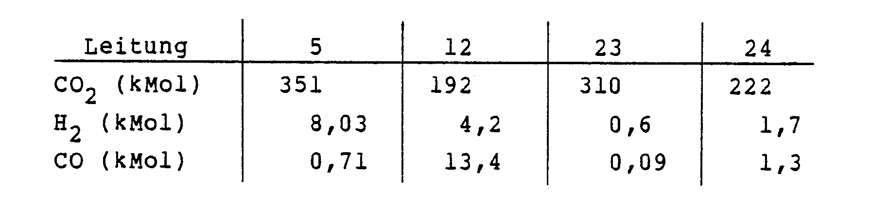
- Bezogen auf den m³ Waschlösung sind das in den Leitungen (5) und (12) pro Stunde:

- Der Druck in den beiden Entspannungszonen liegt bei etwa 11 bar.
- In der Wertgas-Rückführleitung (21) findet man die in der nachfolgenden Tabelle in Spalte A angegebenen Gase. Zum Vergleich gibt die Spalte B die Summe der Gasmengen in den Leitungen (16) und (21) an, wenn man das Entspannungsgas in der Leitung (16) nicht in die zweite Entspannungszone (17) leiten sondern getrennt halten würde:
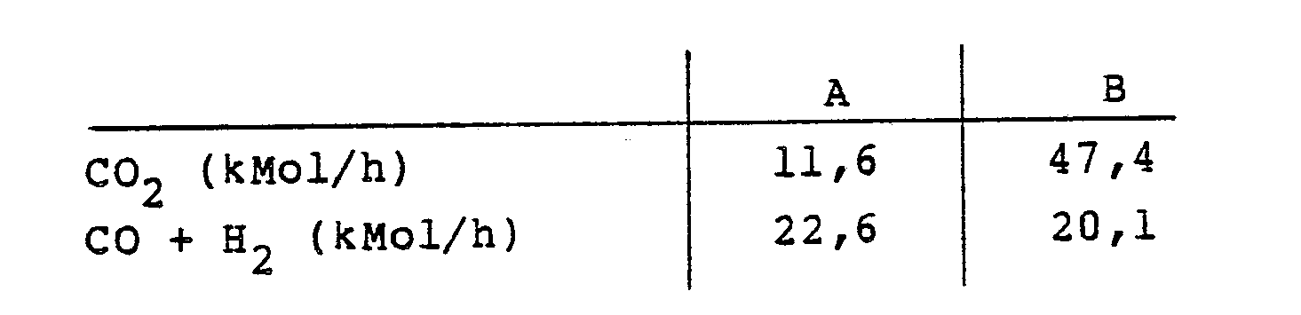
- Im Fall A beträgt die CO-Restmenge in den der Regenerierung zugeführten Waschlösungsströmen insgesamt pro Stunde 1,51 kMol und im Fall B 4,79 kMol. Man sieht aus der Tabelle, daß die Summe der Gasmengen bei der erfindungsgemäßen Verfahrensführung (Spalte A) klein ist, so daß zum Rückführen der Gase nur wenig Kompressionsaufwand nötig ist. Gleichzeitig wird eine größere Menge an Wertgasen, CO + H₂, zurückgewonnen.
Claims (4)
Applications Claiming Priority (2)
| Application Number | Priority Date | Filing Date | Title |
|---|---|---|---|
| DE3709363A DE3709363C1 (de) | 1987-03-21 | 1987-03-21 | Verfahren zum Behandeln zweier beladener Waschloesungsstroeme |
| DE3709363 | 1987-03-21 |
Publications (2)
| Publication Number | Publication Date |
|---|---|
| EP0284121A1 true EP0284121A1 (de) | 1988-09-28 |
| EP0284121B1 EP0284121B1 (de) | 1990-03-14 |
Family
ID=6323702
Family Applications (1)
| Application Number | Title | Priority Date | Filing Date |
|---|---|---|---|
| EP88200314A Expired - Lifetime EP0284121B1 (de) | 1987-03-21 | 1988-02-22 | Verfahren zum Behandeln zweier beladener Waschlösungsströme |
Country Status (9)
| Country | Link |
|---|---|
| US (1) | US4830639A (de) |
| EP (1) | EP0284121B1 (de) |
| CN (1) | CN1020746C (de) |
| BR (1) | BR8706359A (de) |
| CA (1) | CA1306232C (de) |
| DD (1) | DD270539A5 (de) |
| DE (2) | DE3709363C1 (de) |
| GR (1) | GR3001002T3 (de) |
| PT (1) | PT87027B (de) |
Families Citing this family (10)
| Publication number | Priority date | Publication date | Assignee | Title |
|---|---|---|---|---|
| JPH0418911A (ja) * | 1990-05-14 | 1992-01-23 | Toho Chem Ind Co Ltd | ガスから酸性成分を除去する方法 |
| US5529612A (en) * | 1995-05-23 | 1996-06-25 | Southern Petroleum Laboratories, Inc. | Method and system for removing volatile organics from landfill gas |
| US6352575B1 (en) * | 2000-06-05 | 2002-03-05 | Ch2M Hill, Inc. | Apparatus and method for centralized recovery of volatile organic compounds |
| US6726750B2 (en) | 2000-06-05 | 2004-04-27 | Ch2M Hill, Inc. | Apparatus and method for efficient recovery of volatile organic compounds |
| EP1419127B1 (de) * | 2001-08-24 | 2008-12-17 | Shell Internationale Researchmaatschappij B.V. | Verfahren zur herstellung von kohlenwasserstoffen |
| US20060101715A1 (en) * | 2004-11-17 | 2006-05-18 | Karel Vlok | Apparatus and method for coal gasification |
| DE102007048565B3 (de) * | 2007-10-09 | 2009-01-22 | Dge Dr.-Ing. Günther Engineering Gmbh | Verfahren und Anlage zur Regeneration einer bei der Reinigung von Gasen anfallenden aminhaltigen Waschlösung |
| DE102007055296A1 (de) * | 2007-11-20 | 2009-05-28 | Linde Aktiengesellschaft | Verfahren und Vorrichtung zur Waschmittelregenerierung |
| JP6143939B2 (ja) * | 2014-02-21 | 2017-06-07 | シャープ株式会社 | 二酸化炭素濃度制御装置および電子機器 |
| JP6351729B2 (ja) | 2014-08-20 | 2018-07-04 | シャープ株式会社 | 二酸化炭素濃度制御システムおよび二酸化炭素濃度制御装置 |
Citations (3)
| Publication number | Priority date | Publication date | Assignee | Title |
|---|---|---|---|---|
| DE1494806A1 (de) * | 1966-10-14 | 1969-05-22 | Metallgesellschaft Ag | Verfahren zur Entfernung von Schwefelwasserstoff und Kohlendioxyd aus Brenn- und Synthesegasen |
| US3710546A (en) * | 1971-09-16 | 1973-01-16 | Metallgesellschaft Ag | Process for the removal of hydrogen sulfide and carbon dioxide from fuel gases and synthesis gases |
| DE3427633A1 (de) * | 1983-07-26 | 1985-02-07 | Bechtel International Corp., San Francisco, Calif. | Vorrichtung und verfahren zur entschwefelung von gasfoermigem brennstoff |
Family Cites Families (14)
| Publication number | Priority date | Publication date | Assignee | Title |
|---|---|---|---|---|
| US3121624A (en) * | 1961-05-29 | 1964-02-18 | Union Carbide Corp | Process and apparatus for purifying gases by absorption |
| US3435590A (en) * | 1967-09-01 | 1969-04-01 | Chevron Res | Co2 and h2s removal |
| US3594985A (en) * | 1969-06-11 | 1971-07-27 | Allied Chem | Acid gas removal from gas mixtures |
| DE2226215C3 (de) * | 1972-05-30 | 1975-09-25 | Metallgesellschaft Ag, 6000 Frankfurt | Verfahren zur Regeneration eines beladenen Absorptionsmittels, das beim Auswaschen von sauren Komponenten aus Gasen anfällt |
| FR2376683A1 (fr) * | 1977-01-06 | 1978-08-04 | Elf Aquitaine | Procede d'absorption selective de l'hydrogene sulfure par des solvants soufres |
| US4252548A (en) * | 1979-01-02 | 1981-02-24 | Kryos Energy Inc. | Carbon dioxide removal from methane-containing gases |
| DE2923012A1 (de) * | 1979-06-07 | 1980-12-18 | Basf Ag | Verfahren zur gleichzeitigen entfernung von wasser und schwefelwasserstoff aus gasen |
| US4282194A (en) * | 1980-02-19 | 1981-08-04 | Exxon Research & Engineering Co. | Process for converting cyclic urea to corresponding diamine in a gas treating system |
| DE3036936A1 (de) * | 1980-09-30 | 1982-05-27 | Linde Ag, 6200 Wiesbaden | Verfahren und vorrichtung zum regulieren des ammoniakgehaltes im waschmittel einer gaswaesche |
| US4460385A (en) * | 1982-11-26 | 1984-07-17 | Exxon Research And Engineering Co. | Process for the removal of acid gases from hydrocarbon gases containing the same |
| IT1193602B (it) * | 1983-01-19 | 1988-07-21 | Snam Progetti | Procedimento criogenico di rimozione di gas acidi da miscele di gas mediante solvente |
| DE3308088A1 (de) * | 1983-03-08 | 1984-09-27 | Basf Ag, 6700 Ludwigshafen | Verfahren zum entfernen von co(pfeil abwaerts)2(pfeil abwaerts) und/oder h(pfeil abwaerts)2(pfeil abwaerts)s aus gasen |
| US4498911A (en) * | 1983-06-29 | 1985-02-12 | Shell Oil Company | Simultaneous removal of water and hydrogen sulfide from gaseous carbon dioxide |
| DE3520934C1 (de) * | 1985-06-12 | 1986-06-05 | Metallgesellschaft Ag, 6000 Frankfurt | Verfahren zum Gewinnen von Ammoniak aus einem NH3,CO2 und H2S enthaltenden Abwasser |
-
1987
- 1987-03-21 DE DE3709363A patent/DE3709363C1/de not_active Expired
- 1987-11-25 BR BR8706359A patent/BR8706359A/pt unknown
-
1988
- 1988-02-22 EP EP88200314A patent/EP0284121B1/de not_active Expired - Lifetime
- 1988-02-22 DE DE8888200314T patent/DE3860053D1/de not_active Expired - Lifetime
- 1988-03-14 US US07/167,563 patent/US4830639A/en not_active Expired - Lifetime
- 1988-03-18 DD DD88313812A patent/DD270539A5/de not_active IP Right Cessation
- 1988-03-18 CA CA000561824A patent/CA1306232C/en not_active Expired - Lifetime
- 1988-03-18 PT PT87027A patent/PT87027B/pt not_active IP Right Cessation
- 1988-03-19 CN CN88101352A patent/CN1020746C/zh not_active Expired - Lifetime
-
1990
- 1990-03-15 GR GR90400096T patent/GR3001002T3/el unknown
Patent Citations (3)
| Publication number | Priority date | Publication date | Assignee | Title |
|---|---|---|---|---|
| DE1494806A1 (de) * | 1966-10-14 | 1969-05-22 | Metallgesellschaft Ag | Verfahren zur Entfernung von Schwefelwasserstoff und Kohlendioxyd aus Brenn- und Synthesegasen |
| US3710546A (en) * | 1971-09-16 | 1973-01-16 | Metallgesellschaft Ag | Process for the removal of hydrogen sulfide and carbon dioxide from fuel gases and synthesis gases |
| DE3427633A1 (de) * | 1983-07-26 | 1985-02-07 | Bechtel International Corp., San Francisco, Calif. | Vorrichtung und verfahren zur entschwefelung von gasfoermigem brennstoff |
Also Published As
| Publication number | Publication date |
|---|---|
| CA1306232C (en) | 1992-08-11 |
| CN88101352A (zh) | 1988-10-05 |
| BR8706359A (pt) | 1988-10-04 |
| GR3001002T3 (en) | 1991-12-30 |
| EP0284121B1 (de) | 1990-03-14 |
| DE3860053D1 (de) | 1990-04-19 |
| PT87027A (pt) | 1988-04-01 |
| US4830639A (en) | 1989-05-16 |
| PT87027B (pt) | 1992-09-30 |
| DE3709363C1 (de) | 1988-08-18 |
| DD270539A5 (de) | 1989-08-02 |
| CN1020746C (zh) | 1993-05-19 |
Similar Documents
| Publication | Publication Date | Title |
|---|---|---|
| EP0359991B2 (de) | Verfahren zum Entfernen von CO2 und gegebenenfalls H2S aus Gasen | |
| DE1494809C3 (de) | Verfahren zum Auswaschen von Kohlendioxid aus schwefelarmen oder schwefelfreien Gasen | |
| DE2548700C2 (de) | Verfahren und Vorrichtung zur Wasserstoffreinigung unter gleichzeitiger Kohlendioxidgewinnung | |
| DE2527985C3 (de) | Kontinuierliches Verfahren zur Gewinnung von reinem Ammoniak | |
| EP2215009B1 (de) | Verfahren zur behandlung eines co2 enthaltenden prozessgasstroms | |
| EP1409114B1 (de) | Verfahren zur reinigung von kokereigas | |
| EP0012986A1 (de) | Verfahren zum Abtrennen und Gewinnen gasförmiger Komponenten aus einem Gasgemisch durch physikalische Wäsche | |
| EP0284121B1 (de) | Verfahren zum Behandeln zweier beladener Waschlösungsströme | |
| DE3247773C2 (de) | ||
| DE3709364C1 (de) | Verfahren zum Regenerieren von mit Kohlendioxid und Kohlenoxysulfid beladenen Waschloesungsstroemen | |
| EP0408100B1 (de) | Verfahren zum Regenerieren einer hochsiedenden, CO2 und H2S enthaltenden Waschlösung | |
| EP0285189B1 (de) | Verfahren zum Behandeln einer beladenen, unter Druck stehenden Waschlösung | |
| EP0279494A2 (de) | Verfahren zur Entschwefelung von Gasen | |
| EP0192195B1 (de) | Verfahren und Vorrichtung zum Abtrennen unerwünschter Komponenten aus Gasgemischen | |
| EP0361557B1 (de) | Verfahren zum Behandeln eines Kohlenwasserstoffe und H2S enthaltenden Erdgases | |
| DE3030435C2 (de) | Verfahren zum insbesondere mehrstufigen Auswaschen von sauren Bestandteilen wie CO↓2↓, HCN und insbesondere H↓2↓S aus Gasen, insbesondere Koksofengas, mittels einer ammoniakalischen Kreislaufwäsche | |
| EP0325956B1 (de) | Verfahren zum Reinigen eines Gasgemisches | |
| EP0520316B1 (de) | Verfahren zur selektiven H2S-Auswaschung | |
| DE4235957C2 (de) | Verfahren zur getrennten Entfernung von Schwefelverbindungen und CO¶2¶ aus Gas | |
| DE3738913A1 (de) | Verfahren und vorrichtung zur auswaschung von sauergasen aus gasgemischen | |
| DE3340631A1 (de) | Verfahren zum trennen von gas- und/oder fluessigkeitsgemischen | |
| DE1592350C (de) | Verfahren und Anlage zum Regenerieren beladener Waschflussigkeiten | |
| DE3626562A1 (de) | Verfahren zur gewinnung von argon aus einem gasgemisch | |
| DE1027190B (de) | Verfahren zur Gewinnung schwefelwasserstoff- und/oder blausaeurereicher Fraktionen aus Gasen, die daneben Kohlendioxyd und gegebenenfalls weitere Bestandteile enthalten | |
| DE3801712A1 (de) | Verfahren zum reinigen eines gasgemisches |
Legal Events
| Date | Code | Title | Description |
|---|---|---|---|
| PUAI | Public reference made under article 153(3) epc to a published international application that has entered the european phase |
Free format text: ORIGINAL CODE: 0009012 |
|
| AK | Designated contracting states |
Kind code of ref document: A1 Designated state(s): DE FR GB GR NL SE |
|
| 17P | Request for examination filed |
Effective date: 19881024 |
|
| 17Q | First examination report despatched |
Effective date: 19890802 |
|
| GRAA | (expected) grant |
Free format text: ORIGINAL CODE: 0009210 |
|
| AK | Designated contracting states |
Kind code of ref document: B1 Designated state(s): DE FR GB GR NL SE |
|
| REF | Corresponds to: |
Ref document number: 3860053 Country of ref document: DE Date of ref document: 19900419 |
|
| ET | Fr: translation filed | ||
| GBT | Gb: translation of ep patent filed (gb section 77(6)(a)/1977) | ||
| PLBE | No opposition filed within time limit |
Free format text: ORIGINAL CODE: 0009261 |
|
| STAA | Information on the status of an ep patent application or granted ep patent |
Free format text: STATUS: NO OPPOSITION FILED WITHIN TIME LIMIT |
|
| 26N | No opposition filed | ||
| REG | Reference to a national code |
Ref country code: GR Ref legal event code: FG4A Free format text: 3001002 |
|
| EAL | Se: european patent in force in sweden |
Ref document number: 88200314.8 |
|
| PGFP | Annual fee paid to national office [announced via postgrant information from national office to epo] |
Ref country code: GR Payment date: 19951228 Year of fee payment: 9 |
|
| PG25 | Lapsed in a contracting state [announced via postgrant information from national office to epo] |
Ref country code: GR Free format text: THE PATENT HAS BEEN ANNULLED BY A DECISION OF A NATIONAL AUTHORITY Effective date: 19970831 |
|
| REG | Reference to a national code |
Ref country code: GR Ref legal event code: MM2A Free format text: 3001002 |
|
| REG | Reference to a national code |
Ref country code: GB Ref legal event code: IF02 |
|
| PGFP | Annual fee paid to national office [announced via postgrant information from national office to epo] |
Ref country code: SE Payment date: 20070213 Year of fee payment: 20 Ref country code: NL Payment date: 20070213 Year of fee payment: 20 |
|
| PGFP | Annual fee paid to national office [announced via postgrant information from national office to epo] |
Ref country code: GB Payment date: 20070216 Year of fee payment: 20 Ref country code: DE Payment date: 20070216 Year of fee payment: 20 |
|
| REG | Reference to a national code |
Ref country code: GB Ref legal event code: PE20 |
|
| NLV7 | Nl: ceased due to reaching the maximum lifetime of a patent |
Effective date: 20080222 |
|
| EUG | Se: european patent has lapsed | ||
| PG25 | Lapsed in a contracting state [announced via postgrant information from national office to epo] |
Ref country code: NL Free format text: LAPSE BECAUSE OF EXPIRATION OF PROTECTION Effective date: 20080222 |
|
| PGFP | Annual fee paid to national office [announced via postgrant information from national office to epo] |
Ref country code: FR Payment date: 20070212 Year of fee payment: 20 |
|
| PG25 | Lapsed in a contracting state [announced via postgrant information from national office to epo] |
Ref country code: GB Free format text: LAPSE BECAUSE OF EXPIRATION OF PROTECTION Effective date: 20080221 |