EP0283683B1 - Tragbares schnurloses Kommunikationssystem und Verfahren - Google Patents
Tragbares schnurloses Kommunikationssystem und Verfahren Download PDFInfo
- Publication number
- EP0283683B1 EP0283683B1 EP88101646A EP88101646A EP0283683B1 EP 0283683 B1 EP0283683 B1 EP 0283683B1 EP 88101646 A EP88101646 A EP 88101646A EP 88101646 A EP88101646 A EP 88101646A EP 0283683 B1 EP0283683 B1 EP 0283683B1
- Authority
- EP
- European Patent Office
- Prior art keywords
- base station
- base stations
- radio
- hand
- control information
- Prior art date
- Legal status (The legal status is an assumption and is not a legal conclusion. Google has not performed a legal analysis and makes no representation as to the accuracy of the status listed.)
- Expired - Lifetime
Links
Images


Classifications
-
- H—ELECTRICITY
- H04—ELECTRIC COMMUNICATION TECHNIQUE
- H04W—WIRELESS COMMUNICATION NETWORKS
- H04W72/00—Local resource management
- H04W72/20—Control channels or signalling for resource management
- H04W72/27—Control channels or signalling for resource management between access points
-
- H—ELECTRICITY
- H04—ELECTRIC COMMUNICATION TECHNIQUE
- H04W—WIRELESS COMMUNICATION NETWORKS
- H04W84/00—Network topologies
- H04W84/02—Hierarchically pre-organised networks, e.g. paging networks, cellular networks, WLAN [Wireless Local Area Network] or WLL [Wireless Local Loop]
- H04W84/10—Small scale networks; Flat hierarchical networks
- H04W84/16—WPBX [Wireless Private Branch Exchange]
-
- H—ELECTRICITY
- H04—ELECTRIC COMMUNICATION TECHNIQUE
- H04W—WIRELESS COMMUNICATION NETWORKS
- H04W92/00—Interfaces specially adapted for wireless communication networks
- H04W92/16—Interfaces between hierarchically similar devices
- H04W92/20—Interfaces between hierarchically similar devices between access points
Definitions
- the present invention relates to portable wireless communication system and method as described in the pre-characterizing part of claims 1 and 7, respectively.
- Such a system and method are known from EP-A-0 126 557.
- indoor portable wireless communication systems To further enhance mobile telephone systems for the purpose of obtaining a broader service area of wireless telephones, so-called indoor portable wireless communication systems have been widely studied which systems allow wireless telephones to be used indoors at buildings, underground streets, airports or the like.
- the characteristics of indoor portable wireless communication is available at any location within a total service area extending indoors at a building or on the premises of a factory, and that such communication is allowed to be conducted while a subscriber station is moving.
- the indoor radio propagation characteristics are often unknown. Even if they are known previously, it may be expected that they change to large extent due to a change of an indoor layout or the like. It is difficult accordingly to provide a fixed cell structure as seen in conventional mobile telephone systems, where base stations are installed systematically.
- a portable wireless communication system has been proposed as in Japanese Patent Laid-open Application JP-A-61-244137, which system performs "automatically" the management and allocation of radio frequencies or channels in such a manner that each of the base stations disposed at irregular intervals independently judges what channels are available, and determines a priority order in which the channels should be selected when used for communication with a subscriber station based on learning from the past history.
- the proposed portable wireless communication system performs an autonomic processing only for the operation of channel allocation.
- Other technical factors required for the processings before the channel allocation such as the call initiation from a subscriber station for determining the base station which is to be communicated with the subscriber station, the hand-off of the communication exchange according to movement of a subscriber station and the like, cannot be autonomically processed without a help of the control by an additionally installed management controller.
- a cellular mobile radio communication system and method in which, when a mobile unit goes beyond the radio range of its associated controlled base station, that base station sends a message to a central switching office and from there to nearby base stations, to measure the strength of the received signal from that mobile.
- the measurement results are returned to the first-mentioned base station by the switching office, and the base station generates a hand-off request message including a list of candidate hand-off base stations and sends it to the central switching office.
- the central switching office selects one of the base stations and an available channel.
- a control system with a similar structure for cellular radio communication having a central controller is known from US-A-4 163 121.
- the communication system and method of this invention are constructed such that lines are provided among the base stations disposed at arbitrary intervals for exchanging beforehand control information on radio channel use status, use availability status and other internal status between each base station and its neighbouring base stations, and means is provided at each base station by which each base station autonomically performs the management of radio channels based on the exchange information, as it is described in the characterizing part of claims 1 and 7, respectively.
- each base station since each base station has the control informations on neighbouring base stations, each base station can independently judges the concerned conditions for processing hand-off and call initiation from a subscriber station and performs following processings.
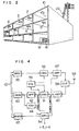
- Fig. 1 shows an embodiment of the arrangement of the portable wireless communication systems of this invention.
- the base stations 1 to 8 are installed in respective rooms of a building 10 as shown in Fig. 2 and communicate at a radio intensity higher than a predetermined level in the service area 11 to 17, respectively.
- a building or the like to which the present invention is principally applied there are many materials such as walls, lockers and the like which absorb and reflect radio waves. Consequently, the shape of each service area 11 to 17 of the base station does not become an ideal circle but it takes three-dimensionally complicated configuration.
- the indoor layout is often changed so that the radio propagation characteristics and the shape of service areas change.
- subscriber stations 51 and 52 can communicate with a plurality of base stations due to the overlap of the service areas.
- neighbouring base stations communicate with subscriber stations using the same frequency, interference between them may occurs. Also between neighbouring base stations whose service areas do not overlap, interference may occur if the distance between them is short.
- communication lines 40 to 49 are mounted between base stations 1 to 7 which have a possibility of interference therebetween.
- Each radio station exchanges control information on channel use status, use availability status and other internal status with other neighbouring base stations, and autonomically performs the management of radio channels based on the exchanged control information so as not to interfere with other niehgbouring base stations.
- Each base station 1 to 7 is connected to a radio exchange 18 via communication lines 31 to 37.
- the radio exchange 18 is connected to a wire exchange 19 for exchange with wire telephones 21 to 23 in the building, and further with wire telephones in other buildings via wires 20.
- the base stations 1 to 7 autonomically perform the radio frequency channel allocation so that the radio exchange concerns no channel allocation but only the exchange operation.
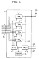
- Fig. 3 shows an embodiment of the structure of the base station 1.
- the base station 1 includes transceiver units 1-1, 1-2, 1-3 and 1-4, a data exchange transceiver 1-5, a memory 1-6, a controller 1-7.
- transceiver units 1-1 to 1-4 There are as many transceiver units 1-1 to 1-4 as the number of subscriber stations which can be used at the same time within the service area of the base station 1.
- the data exchange transceiver 1-5 is connected to lines 46 and 47 for the exchange of control information data with neighbouring base stations.
- the memory 1-6 stores the control information data transmitted from and received by the data exchange transceiver 1-5.
- the controller 1-7 (which may be constructed of a microcomputer) controls the frequency channel allocation for the plurality of transceivers 101 to 1-4 and the management of their operation status, by referring to the control information data stored in the memory 1-6.
- the transceiver units 1-1 to 1-4 communicate with the subscriber stations 51 and 52 via an antenna 53, and are connected via the communication line 31 to the radio exchange 18 and/or the wire exchange 19.
- Fig. 4 shows one example of the structure of the transceiver unit provided in the base station.
- the transceiver unit includes a microprocessor unit 54, a modulator 55 for audio signals, a frequency converter 56 and a high frequency amplifier 57 whose output power may preferably be variable.
- the transceiver unit further includes a duplexer 58, a frequency synthesizer 59, a receiver amplifier 60, a frequency converter 61, a band-pass filter 62, a demodulator 63 for audio signals, an envelope detector 64 for received signals which is provided for measuring signal strength and interference strength during communication, and a modem 65 for sending and receiving digital control signals to and from the associated subscriber station.
- the transceiver unit as constructed above is almost similar to a conventional known one, as shown in, for example, "Lightweight Handheld Portable Cordless Telephone Set” by Kawasaki et al, NTT report of Research in Practical Use 1986, Vol. 35, No. 2, pages 191-197, so that the detailed description therefor is omitted.
- Fig. 5 is a block diagram showing an example of a subscriber station.
- the subscriber station includes an antenna 501, a duplexer 502, a frequency synthesizer 503, a band-pass filter 504, a detector 505, an audio amplifier 506, a frequency synthesizer 507, a microphone amplifier 508, a modulator 509, a frequency converter 510, a band-pass filter 511, a radio frequency amplifier 512, a microcomputer unit 513, a modem 514 for digital signals, a sound generator 515 such as a bell or a buzzer informing a call reception, a battery 516 for powering the subscriber station, a dial pad and display section 517, a microphone 518 and a loudspeaker 519.
- the structure of the subscriber station is also the same as that of a conventionally known radio mobile station, as shown in, for example, "Cordless Telephone Equipment Meeting CEPT Standards” by Nishihara et al. NEC Res. & Develop., No. 82, July 1986, pages 104-109 so that the detailed description therefor is omitted.
- each base station 1 to 7 sequentially monitors radio channels allotted to the system at a time interval during which it does not communicate with any of the subscriber stations 51 and 52, and checks which channel is vacant or in use. Assuming that the number of channels assigned to the portable wireless communication systems of this invention is in the order of several tens, checking the radio channels is performed in accordance with the following procedure.
- the microcomputer unit 54 shown in Fig. 3 determines a channel check order in accordance with a predetermined order, and causes the frequency synthesizer 59 to set at the frequency of a radio channel in accordance with the channel check order.
- the amplifier 60 is allowed to receive the radio channel.
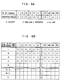
- the microcomputer unit 54 monitors an output from the receiver 60 to read a signal strength of the radio channel and store it in the memory 1-6. In this case, the received signal strength is compared with signal strength threshold values to judge if the radio channel is in use because of there is interference from other channels, can be used because of negligible interference or is vacant because of no signal from other channels.
- the result is stored in the memory 1-6.
- An example of stored results is shown in Fig. 6A, and a flow chart illustrating the check procedure is shown in Fig. 7. The check procedure is always performed continuously while the base station does not communicate with a subscriber station.
- a plurality of transceivers are present in a base station as shown in Fig. 3, it is possible to known the idle or busy status of radio channels in short time by operating in paralle all the receivers which do not communicate with a subscriber station.
- the controller 1-7 causes the monitor result (control information) of a base station exemplarily shown in Fig. 6A to be sent to neighbouring base stations and causes the monitor results of neighbouring base stations to be received, respectively via the data exchange transceiver 1-5 and the communication lines 46 and 47 at predetermined time intervals or every time the idle or busy status changes.
- the memory 5-1 stores the monitor results including the idle or busy status monitored by its own base station and the idle or busy status monitored by neighbouring base stations, an example of which is shown in Fig. 6B.
- FIG. 6B illustrates the contents of the memory of the base station 1 wherein the base stations 2 to 4 are registered as neighbouring base stations of the base station 1. It is assumed here that the other base stations are remotely located from the base station 1 and give no influence upon channel allocation of the base station 1.
- the monitor results or control information data of channels have been described as being sent or received via the communication lines 46 and 47.
- the monitor results may be sent or received via a path of the data exchange transceiver 1-5, the line 1-8 and antenna 53 shown in Fig. 3 by using a radio channel dedicated to such data exchange.
- Fig. 8 shows one example of channel allocation wherein channels CH1 to CH50 are audio channels for telephone communication, channel CH CONT is a channel used for the control signals for a call initiation, a call reception, a hand-off and the like, and channel CH DATA is a channel used for the exchange of the control information data.
- control channel CH CONT may be used in common.
- a packet communication system with a well known CSMA carrier sense multiple access
- the control information data includes (1) an ID (identification) number of a base station, (2) a channel number whose channel is used in communication of a base station with a subscriber station, (3) a channel number whose channel is in use by another base station so that a base station concerned cannot use it due to the interference, (4) a signal strength of a subscriber station in case there is a transceiver unit communicating with the subscriber station, and (5) the degree of interference by which a radio channel is inhibited to be used.
- Each base station sends and receives the control information at constant intervals or every time the control information changes, to thereby attend to the status of neighbouring base stations.
- a signal strength is measured when the control information is received, an approximate distance to a neighbouring base station can be known based on the signal strength. It is apparent that the nearer the neighbouring base station is, the more a base station concerned receives the influence therefrom. Therefore, obviously the channel management can be effected more effectively if the received signal strength is used in weighting the control information data.
- the microcomputer unit 54 refers to the control information on its own base station and neighbouring base stations stored in the memory 1-6. Then, searched from the list of control information, selected is a radio channel which is vacant at its own base station and is in-use state, i.e., is impossible to use due to the co-channel interferer, at neighbouring base stations.
- radio channel No. 5 is selected since it is vacant at its base station and in-use state at two neighbouring base stations.
- the base station assigned a new radio channel causes the frequency synthesizer 59 to be set at the frequency of the assigned radio channel No. 5 to start communication with the subscriber station.
- the fact that the radio channel No. 5 has been occupied and now in use is declared to the neighbouring base stations via the controller 1-7.
- the declaration is constructed of digital signals in the form of packets including at least the ID number of the base station concerned and the channel number now in use.
- the neighbouring base stations receiving the declaration monitor the radio channel stated in the declaration and checks the received signal strength of the radio channel to accordingly update the control information. Therefore, if the base station assigned the new radio station collects the control information from the neighbouring base stations after a certain time lapse after starting the use of the radio channel, the base station can be informed of the influence of its radio wave upon the neighbouring base stations. Namely, it can dynamically identify those neighbouring base stations within its interference area. As a result, even if radio propagation characteristics change and the size and shape of interference area of each base station fluctuates, the base station concerned in the portable wireless communication systems can autonomically recognize the configuration of interference area.
- the microcomputer unit 513 When an owner of a subscriber station sends a call initiation from the dial pad 517, the microcomputer unit 513 causes the synthesizer 507 to set at a frequency of the common control channel (CH CONT ) and causes the call initiation signal to be modulated by the modem 514 to thereby transmit it via the audio signal modulator 509, frequency converter 510, band-pass filter 511, radio frequency amplifier 512, duplexer 502 and antenna 501.
- CH CONT common control channel
- the other base stations are monitoring the CH CONT through a vacant transceiver unit if they have such a vacant transceiver unit. Therefore, the call initiation signal is properly seized by a radio station having a vacant transceiver unit.
- the base stations seizing the call initiation, exchange data (call initiation response signal) regarding the seize status such as the strength of the call initiation signal. Based on the result of such exchange, each base station compares its seize status with those of neighbouring base stations and judges by itself if it should respond to the call initiation from the subscriber station. For a judgement criterion, the strength of a received call initiation signal is most suitable. However, other factors may be added in such judgement such judgement such as the number of vacant radio channels, the vacant status of transceiver units and the like. It is necessary however for all the base stations to follow the same criterion.
- the call initiation response signal Since the destination base stations to which the call initiation response signal is directed cannot be identified, the call initiation response signal is subjected to error correction coding and broadcast to all neighbouring base stations. Even if such procedure is adopted, only a single base station cannot always respond to the call initiation from the subscriber station due to such as transmission error.
- each base station judges that it should respond to the subscriber station, the former sends to the latter a call initiation acknowledge signal including the channel number to be used.
- the subscriber station receives call initiation acknowledge signals from a plurality of base stations, it is arranged such that the subscriber station returns a call initiation certificate signal to the base station which first responded to the call initiation signal. If alternatively there is no call initiation acknowledge signal from any base station, it is arranged such that the subscriber station sends again a call initiation signal.
- the subscriber station receiving the call initiation certificate signal moves to the radio channel designated by that signal.
- the base station sets the vacant transceiver unit at the designated channel and connects the subscriber station to the radio exchange.
- the radio exchange performs no operation but simply connects the private branch exchange 19 thereto.
- the procedure of sending a dial signal after the establishment of a communication line between the subscriber station and the radio station does not differ at all from the case of a conventional cordless telephone, so that the description therefor is omitted.
- a first base station now in communication with the subscriber station broadcasts a hand-off request signal to neighbouring base stations using a predetermined radio channel (refer to Fig. 10).
- the contents of a hand-off request signal include the channel number by which channel the communication with the subscriber station is in progress, the signal strength of the subscriber station, the ID number of the subscriber station and the like.
- a second base station receiving the hand-off request signal from the first base station monitors the subscriber station, checks the signal strength of the subscriber station and resultantly returns a hand-off response signal, by using a vacant transceiver unit if present in the second base station. Alternatively, of not present, the second base station may not respond or may return a signal reporting that it cannot respond. If the monitor result of the subscriber station by using a vacant transceiver unit leads to a judgement that the signal strength is not sufficient for communication, the hand-off response signal is also sent back.
- the first base station having broadcast the hand-off request signal compared hand-off response signals returned from neighbouring base stations, selects a base station which has seized a signal from the subscriber station at a strongest level, and sends a hand-off control signal thereto. At the same time, the first base station notifies the subscriber station to the effect that a hand-off will be performed, by using the radio channel now in use in communication with the subscriber station. Further, the first base station notifies the radio exchange the ID number of the base station to which communication is handed off, and requests the radio exchange to exchange lines. The hand-off is completed by the above-described procedure.
- PBX prepared in a PBX is a dedicated memory which stores the ID number of each base station near portable transceivers (subscriber stations) in the form of "location registration".
- location registration Upon a call reception, a portable transceiver of an objective subscriber station is called from the registered base station.
- each base station densely exchanges data regarding the use status of radio channels with neighbouring base stations so that each base station can autonomically perform channel management. Thus, it becomes unnecessary to install a base station supervising and managing the whole system. Further, each station can predict the degree of interference influencing other base stations while communicating with a subscriber station, thus resulting in efficient frequency allocation.
- each base station dynamiclly manages the radio channels and service area, it becomes unnecessary to change the positional arrangement of base stations even in the indoor layout, where radio propagation characteristics or the like often changes.
Claims (12)
- Tragbares schnurloses Kommunikationssystem mit
einer Anzahl von Basisstationen (1 bis 7), die innerhalb eines bestimmten Gebietes (11 bis 17) verteilt sind;
einer Teilnehmerstation (51, 52), die sich innerhalb des bestimmten Gebietes bewegen kann und die in der Lage ist, über Funkwellenausbreitung mit wenigstens einer der Basisstationen in Verbindung zu treten; und mit
einer Funk-Anschlußeinrichtung (18), die über eine Anzahl von Verbindungsleitungen (31 bis 37) an die Basisstationen und an andere Kommunikationssysteme (19 bis 23) angeschlossen ist, um Informationen zwischen den anderen Kommunikationssystemen und den Basisstationen auszutauschen;
dadurch gekennzeichnet, daß
eine besondere Leitung (40 bis 49) zwischen benachbarten Stationen aus der Anzahl der Basisstationen vorgesehen ist, um Steuerinformationen hinsichtlich der Status der Kommunikation durch die jeweiligen benachbarten Basisstationen auszutauschen; und daß
jede der Basisstationen eine Speichereinrichtung (1-6) zum Speichern der Steuerinformationen, die von benachbarten Basisstationen über die besondere Leitung erhalten werden, und eine Beurteilungseinrichtung (1-7) aufweist, um zu beurteilen, wenn ein Anruf von der Teilnehmerstation erhalten wird, ob die Basisstation dafür geeignet ist, mit der Teilnehmerstation in Verbindung zu treten oder nicht, und um, wenn der Anruf von der Basisstation entgegengenommen werden soll, auf der Basis der in der Speichereinrichtung gespeicherten Steuerinformationen einen Funkkanal auszuwählen, über den die Teilnehmerstation die Kommunikation ausführt. - Tragbares schnurloses Kommunikationssystem nach Anspruch 1, dadurch gekennzeichnet, daß die in der Speichereinrichtung einer jeden Basisstation gespeicherten Steuerinformationen wenigstens umfassen
eine Identifikationsnummer der Basisstation; und
eine Kanalnummer, die jeden der Funkkanäle bezeichnet, der gegenwärtig von der Basisstation benutzt wird; sowie
eine Kanalnummer für jeden der Funkkanäle, der von einer der anderen Basisstationen verwendet wird und der von der Basisstation aufgrund einer möglichen Störung der Kommunikation anderer Basisstationen, die den Funkkanal benutzen, nicht verwendet werden kann. - Tragbares schnurloses Kommunikationssystem nach Anspruch 1, dadurch gekennzeichnet, daß die besondere Leitung ein Funkkanal ist.
- Tragbares schnurloses Kommunikationssystem nach Anspruch 3, dadurch gekennzeichnet, daß jede der Basisstationen des weiteren eine Einrichtung (54) zum Messen der Stärke des Signales, das die Steuerinformationen übermittelt und das über den Funkkanal erhalten wurde, und zum Bewerten der erhaltenen Steuerinformationen entsprechend der gemessenen Stärke des Signales aufweist.
- Tragbares schnurloses Kommunikationssystem nach Anspruch 1, dadurch gekennzeichnet, daß die besondere Leitung eine Drahtleitung ist.
- Tragbares schnurloses Kommunikationssystem nach Anspruch 1, dadurch gekennzeichnet, daß das Kommunikationssystem eine Nebenstellenanlage (19) aufweist, die mit der Funk-Anschlußeinrichtung (18) und Kabeltelephongeräten in dem bestimmten Gebiet verbunden ist.
- Drahtloses Kommunikationsverfahren zum Ausführen einer Kommunikation zwischen einem tragbaren Funksende/Empfangsgerät (51, 52) und einer von einer Anzahl von Basisstationen (1 bis 7), die in einem bestimmten Gebiet (11 bis 17) verteilt sind, über einen aus einer Anzahl von Funkkanälen ausgewählten Funkkanal, die jeder der Basisstationen zugeordnet sind,
dadurch gekennzeichnet, daß
der Zustand des Freiseins oder des Belegtseins der Funkkanäle durch jede der Basisstationen geprüft wird, wenn die Basisstation von der Kommunikation mit dem tragbaren Funksende/Empfangsgerät frei ist, um Steuerinformationen bezüglich des geprüften Zustandes zu gewinnen;
daß jede Basisstation ihre Steuerinformationen zu benachbarten Basisstationen überträgt und die von den benachbarten Basisstationen gewonnenen Steuerinformationen über eine besondere Leitung (40 bis 49) erhält;
daß jede Basisstation die von ihr selbst gewonnenen Steuerinformationen und die von den benachbarten Basisstationen erhaltenen Steuerinformationen speichert;
daß nach dem Erhalt eines Anruf-Initiierungssignales vom tragbaren Funksende/Empfangsgerät jede Basisstation auf die gespeicherten Steuerinformationen Bezug nimmt, um dadurch auf der Basis der Steuerinformationen zu beurteilen, ob der Anruf von ihr selbst entgegengenommen werden soll oder nicht, und daß sie, wenn festgestellt wird, daß der Anruf von ihr selbst entgegengenommen werden soll, einen der Funkkanäle auswählt; und
daß die Basisstation die Kommunikation mit dem tragbaren Funksende/Empfangsgerät über den ausgewählten Funkkanal ausführt. - Drahtloses Kommunikationsverfahren nach Anspruch 7, dadurch gekennzeichnet, daß die Steuerinformationen eine Identifikationsnummer für die Basisstation und Informationen über jeden der Funkkanäle aufweisen, ob der Funkkanal von einer der benachbarten Basisstationen benutzt wird oder nicht, und ob der Funkkanal, der von einer benachbarten Basisstation benutzt wird, durch die Basisstation aufgrund von Störungen bei der Benutzung durch die benachbarte Basisstation nicht verwendet werden kann oder von der Basisstation aufgrund vernachlässigbarer Störungen verwendet werden kann, und
daß bei der Auswahl eines der Funkkanäle derjenige Funkkanal, der von der Basisstation, jedoch nicht von einer der benachbarten Basisstationen verwendet werden kann, vorzugsweise ausgewählt wird. - Drahtloses Kommunikationsverfahren nach Anspruch 7, dadurch gekennzeichnet, daß jede der Basisstationen die Beurteilung, ob der Anruf von ihr selbst entgegengenommen werden soll oder nicht, derart ausführt, daß
jede Basisstation nach Erhalt des Anrufes vom Funksende/Empfangsgerät ein Anruf-Initiierungs-Antwortsignal erzeugt und an die benachbarten Basisstationen aussendet und das Anruf-Initiierungs-Antwortsignal empfängt, das von einer der benachbarten Basisstationen ausgesendet wird; und
daß sie mit Bezug auf das von ihr selbst erzeugte Anruf-Initiierungs-Antwortsignal und das von einer der benachbarten Basisstationen ausgesendete Anruf-Initiierungs-Antwortsignal beurteilt, ob der erhaltene Anruf von ihr selbst entgegengenommen werden soll oder nicht. - Drahtloses Kommunikationsverfahren nach Anspruch 7, dadurch gekennzeichnet, daß jede der Basisstationen, wenn die Signalstärke bei der Kommunikation mit dem Funksende/Empfangsgerät über den ausgewählten Funkkanal kleiner wird, an wenigstens eine der benachbarten Basisstationen ein Weitergabe-Anforderungssignal aussendet, das eine Identifikationsnummer für das Funksende/Empfangsgerät, die Signalstärke und die Nummer des verwendeten Funkkanales beinhaltet; und
daß jede Basisstation, wenn sie von einer der benachbarten Basisstationen ein Weitergabe-Anforderungssignal erhält, das erhaltene Weitergabe-Anforderungssignal überwacht und an die benachbarte Basisstation, von der das Weitergabe-Anforderungssignal erhalten wird, ein Weitergabe-Antwortsignal mit Daten sendet, die die Signalstärke des überwachten Weitergabe-Anforderungssignales anzeigen; und
daß jede Basisstation, wenn sie von einer Anzahl von benachbarten Basisstationen eine Anzahl von Weitergabe-Antwortsignalen erhält, durch Vergleich der Daten, die in den erhaltenen Weitergabe-Antwortsignalen enthalten sind, anhand vorgegebener Vergleichskriterien eine aus der Anzahl der benachbarten Basisstationen auswählt und zu der ausgewählten benachbarten Basisstation ein Weitergabe-Steuersignal sendet, um die Weitergabe der Verbindung daran anzufordern. - Drahtloses Kommunikationsverfahren nach Anspruch 10, dadurch gekennzeichnet, daß jede der Basisstationen, wenn die Basisstation das Weitergabe-Anforderungssignal von einer der benachbarten Basisstationen erhält und die Weitergabe der Verbindung nicht annehmen kann, anstelle des Weitergabe-Antwortsignales ein Signal aussendet, das die Weitergabe der Verbindung ablehnt.
- Drahtloses Kommunikationsverfahren nach Anspruch 10, dadurch gekennzeichnet, daß jede Basisstation die Kommunikation mit dem Funksende/Empfangsgerät fortsetzt, wenn die Basisstation nach dem Aussenden des Weitergabe-Anforderungssignals für eine vorgegebene Zeitspanne kein Weitergabe-Antwortsignal von einer der benachbarten Basisstationen erhält, und daß sie dann das Weltergabe-Anforderungssignal erneut an die benachbarten Basisstationen aussendet.
Applications Claiming Priority (4)
| Application Number | Priority Date | Filing Date | Title |
|---|---|---|---|
| JP63784/87 | 1987-03-20 | ||
| JP62063784A JP2641441B2 (ja) | 1987-03-20 | 1987-03-20 | 移動無線通信方法及び移動無線通信システム |
| JP62279199A JP2602251B2 (ja) | 1987-11-06 | 1987-11-06 | 移動無線通信方法及び無線基地局 |
| JP279199/87 | 1987-11-06 |
Publications (3)
| Publication Number | Publication Date |
|---|---|
| EP0283683A2 EP0283683A2 (de) | 1988-09-28 |
| EP0283683A3 EP0283683A3 (en) | 1989-07-19 |
| EP0283683B1 true EP0283683B1 (de) | 1994-01-12 |
Family
ID=26404910
Family Applications (1)
| Application Number | Title | Priority Date | Filing Date |
|---|---|---|---|
| EP88101646A Expired - Lifetime EP0283683B1 (de) | 1987-03-20 | 1988-02-04 | Tragbares schnurloses Kommunikationssystem und Verfahren |
Country Status (3)
| Country | Link |
|---|---|
| US (1) | US4881271A (de) |
| EP (1) | EP0283683B1 (de) |
| DE (1) | DE3886967T2 (de) |
Families Citing this family (120)
| Publication number | Priority date | Publication date | Assignee | Title |
|---|---|---|---|---|
| US5375161A (en) | 1984-09-14 | 1994-12-20 | Accessline Technologies, Inc. | Telephone control system with branch routing |
| US6201950B1 (en) | 1984-09-14 | 2001-03-13 | Aspect Telecommunications Corporation | Computer-controlled paging and telephone communication system and method |
| US6545589B1 (en) | 1984-09-14 | 2003-04-08 | Aspect Communications Corporation | Method and apparatus for managing telecommunications |
| US5588037A (en) | 1984-09-14 | 1996-12-24 | Accessline Technologies, Inc. | Remote access telephone control system |
| US5752191A (en) | 1984-09-14 | 1998-05-12 | Accessline Technologies, Inc. | Telephone control system which connects a caller with a subscriber AT A telephone address |
| JP2548763B2 (ja) * | 1988-01-25 | 1996-10-30 | 富士通株式会社 | 移動体通信の通話中ゾーン切換え方法と制御交換局 |
| US5673031A (en) * | 1988-08-04 | 1997-09-30 | Norand Corporation | Redundant radio frequency network having a roaming terminal communication protocol |
| US5195127A (en) * | 1988-09-19 | 1993-03-16 | Kabushiki Kaisha Toshiba | Radio telephone system and its control method |
| DE3843565A1 (de) * | 1988-12-23 | 1990-06-28 | Standard Elektrik Lorenz Ag | Funktelefonsystem in form einer nebenstellenanlage |
| JPH02312492A (ja) * | 1989-05-29 | 1990-12-27 | Nec Corp | 移動通信システムにおけるチャネル割り当て方式および基地局配置情報の学習方式 |
| US5701297A (en) * | 1989-09-27 | 1997-12-23 | Motorola, Inc. | Data over cellular |
| US5495482A (en) * | 1989-09-29 | 1996-02-27 | Motorola Inc. | Packet transmission system and method utilizing both a data bus and dedicated control lines |
| US5477541A (en) * | 1989-09-29 | 1995-12-19 | White; Richard E. | Addressing technique for storing and referencing packet data |
| US5093927A (en) * | 1989-10-20 | 1992-03-03 | Motorola, Inc. | Two-way communication system |
| US5148548A (en) * | 1989-12-19 | 1992-09-15 | Northern Telecom Limited | Method of monitoring cellular radio channels to avoid adjacent and co-channel interference |
| JPH048046A (ja) * | 1990-04-26 | 1992-01-13 | Fujitsu Ltd | システムコードレス電話装置の空きチャンネル検索方法および装置 |
| EP0454647B1 (de) * | 1990-04-27 | 1998-06-03 | Telefonaktiebolaget L M Ericsson | Einrichtung und Verfahren zur Anrufvermittlung für mobile Telefonteilnehmer |
| US5153902A (en) * | 1990-04-27 | 1992-10-06 | Telefonaktiebolaget L M Ericsson | Multi-exchange paging system for locating a mobile telephone in a wide area telephone network |
| SE466829B (sv) * | 1990-05-11 | 1992-04-06 | Tateco Ab | Anslutning av traadloesa telefoner till en abonnentvaexel |
| SE466374B (sv) * | 1990-06-25 | 1992-02-03 | Ericsson Telefon Ab L M | Mobiltelefonisystem |
| CA2021382C (en) * | 1990-07-17 | 1998-07-14 | Leo Strawczynski | Radio link architecture for wireless communication systems |
| US5355516A (en) * | 1990-09-28 | 1994-10-11 | Motorola, Inc. | Method for reducing superfluous channel allocation in a cellular radiotelephone communication system |
| CA2050104C (en) | 1990-10-01 | 1995-10-03 | Noach Amitay | Distributed switching cellular communication system |
| US5371780A (en) * | 1990-10-01 | 1994-12-06 | At&T Corp. | Communications resource assignment in a wireless telecommunications system |
| US5384826A (en) * | 1990-10-01 | 1995-01-24 | At&T Bell Laboratories | Distributed packetized switching cellular radio telephone communication system with handoff |
| CA2052466C (en) * | 1990-10-02 | 2001-05-08 | Masayuki Sakamoto | Method of handover and route diversity in mobile radio communication |
| US5274841A (en) * | 1990-10-29 | 1993-12-28 | International Business Machines Corporation | Methods for polling mobile users in a multiple cell wireless network |
| JP2500963B2 (ja) | 1990-10-29 | 1996-05-29 | インターナショナル・ビジネス・マシーンズ・コーポレイション | 双方向情報通信方法 |
| US5239673A (en) * | 1990-10-29 | 1993-08-24 | International Business Machines Corporation | Scheduling methods for efficient frequency reuse in a multi-cell wireless network served by a wired local area network |
| US5068916A (en) * | 1990-10-29 | 1991-11-26 | International Business Machines Corporation | Coordination of wireless medium among a plurality of base stations |
| US5212806A (en) * | 1990-10-29 | 1993-05-18 | International Business Machines Corporation | Distributed control methods for management of migrating data stations in a wireless communications network |
| EP0488173A3 (en) * | 1990-11-27 | 1993-04-28 | Canon Kabushiki Kaisha | Wireless communication channel selecting method |
| US5257399A (en) * | 1990-11-28 | 1993-10-26 | Telefonaktiebolaget L M Ericsson | Multiple access handling in a cellular communications system |
| CA2031551C (en) * | 1990-12-05 | 1998-06-30 | Leo Strawczynski | Inter-cell call hand-over in radio communication systems with dynamic channel allocation |
| US5265150A (en) * | 1991-01-30 | 1993-11-23 | At&T Bell Laboratories | Automatically configuring wireless PBX system |
| JP2653000B2 (ja) * | 1991-04-24 | 1997-09-10 | 日本電気株式会社 | 移動無線通信方式 |
| US6714559B1 (en) * | 1991-12-04 | 2004-03-30 | Broadcom Corporation | Redundant radio frequency network having a roaming terminal communication protocol |
| WO1992021214A1 (en) * | 1991-05-17 | 1992-11-26 | Motorola, Inc. | Channel acquisition method and apparatus for a communication system |
| CA2043127C (en) * | 1991-05-23 | 1996-05-07 | Martin Handforth | Wireless communication zone management system |
| US5335360A (en) * | 1991-06-25 | 1994-08-02 | Motorola, Inc. | Base site selection apparatus and method |
| BR9206187A (pt) * | 1991-06-25 | 1994-11-14 | Motorola Inc | Processo para facilitar o uso de local de base específico e unidade de comunicação |
| JPH06508970A (ja) * | 1991-07-01 | 1994-10-06 | モトローラ・インコーポレイテッド | 補助情報モードを提供するパーソナル通信システム |
| JPH0530025A (ja) * | 1991-07-25 | 1993-02-05 | Canon Inc | コードレス電話装置 |
| SE468965B (sv) * | 1991-08-30 | 1993-04-19 | Ericsson Telefon Ab L M | Kombinerat mobilradiosystem |
| US6407991B1 (en) | 1993-05-06 | 2002-06-18 | Intermec Ip Corp. | Communication network providing wireless and hard-wired dynamic routing |
| NL9102047A (nl) * | 1991-12-09 | 1993-07-01 | Nederland Ptt | Werkwijze voor het tussen centrales overdragen van de behandeling van een actieve verbinding tussen een gebruiker enerzijds en een mobiele terminal anderzijds. |
| US5353331A (en) * | 1992-03-05 | 1994-10-04 | Bell Atlantic Network Services, Inc. | Personal communications service using wireline/wireless integration |
| US5343512A (en) * | 1992-03-27 | 1994-08-30 | Motorola, Inc. | Call setup method for use with a network having mobile end users |
| WO1993020642A1 (en) * | 1992-04-03 | 1993-10-14 | Motorola Inc. | Apparatus and method for servicing wireless subscribers in a wireline environment |
| US5448619A (en) * | 1992-04-14 | 1995-09-05 | Orion Industries, Inc. | Apparatus and a method of allowing private cellular operation within an existing public cellular system |
| US5448750A (en) * | 1992-04-22 | 1995-09-05 | Telefonaktiebolaget Lm Ericsson | Segregation method of dynamic channel allocation in a mobile radio system |
| US5410737A (en) * | 1992-04-27 | 1995-04-25 | American Pcs L.P. | Frequency agile sharing technology (FAST) for a personal communications service system |
| US5752164A (en) * | 1992-04-27 | 1998-05-12 | American Pcs L.P. | Autonomous remote measurement unit for a personal communications service system |
| US5315637A (en) * | 1992-05-01 | 1994-05-24 | Motorola, Inc. | Apparatus and method for controlling the routing of incoming calls in a wireless communication system |
| EP0582373B1 (de) * | 1992-07-17 | 1999-10-06 | Sun Microsystems, Inc. | Verfahren und Gerät zur Selbstorganisation in einem drahtlosen lokalen Netz |
| US5285443A (en) * | 1992-08-25 | 1994-02-08 | Motorola, Inc. | Method and apparatus for synchronizing a time division duplexing communication system |
| EP0589552B1 (de) * | 1992-09-08 | 2002-10-23 | Sun Microsystems, Inc. | Verfahren und Vorrichtung zur Verbindungsmöglichkeitserhaltung von Knoten in einem drahtlosen lokalen Netz |
| CA2107820A1 (en) * | 1992-10-16 | 1994-04-17 | Keith Daniel O'neill | Low-power wireless system for telephone services |
| FI96156C (fi) * | 1992-11-18 | 1996-05-10 | Nokia Telecommunications Oy | Menetelmä ja järjestelmä tietoliikenneyhteyden muodostamiseksi rajoitetulla kutsualueella sijaitseville tietoliikennelaitteille |
| JP2878052B2 (ja) * | 1993-01-12 | 1999-04-05 | 日本電気通信システム株式会社 | 電界レベル測定エリア制御方式 |
| US5463673A (en) * | 1993-04-29 | 1995-10-31 | Northern Telecom Limited | In-building radio deployment technique for wireless personal communications systems |
| US5457680A (en) * | 1993-05-18 | 1995-10-10 | International Business Machines Corporation | Data gateway for mobile data radio terminals in a data communication network |
| JPH08501917A (ja) * | 1993-07-20 | 1996-02-27 | モトローラ・インコーポレイテッド | 無線通信システム操作回路および操作方法 |
| GB9316813D0 (en) * | 1993-08-12 | 1993-09-29 | Macnamee Robert J G | Cordless telephone system |
| DE4330704A1 (de) * | 1993-09-10 | 1995-03-16 | Sel Alcatel Ag | Telepoint-System |
| JP2502468B2 (ja) * | 1993-09-30 | 1996-05-29 | インターナショナル・ビジネス・マシーンズ・コーポレイション | 複数の無線移動局を有する構内無線通信システムの通信制御方法 |
| CA2118273C (en) * | 1993-11-23 | 2000-04-25 | Pi-Hui Chao | Method and apparatus for dynamic channel allocation for wireless communication |
| US5724665A (en) * | 1993-11-24 | 1998-03-03 | Lucent Technologies Inc. | Wireless communication base station |
| ATE265127T1 (de) | 1994-02-24 | 2004-05-15 | Gte Wireless Service Corp | Zellulares funktelefon mit wahlnummeranalyse |
| US6453178B1 (en) | 1994-02-24 | 2002-09-17 | Gte Wireless Service Corporation | Radiotelephone operating method with connected NPA dialing analysis |
| US5594782A (en) * | 1994-02-24 | 1997-01-14 | Gte Mobile Communications Service Corporation | Multiple mode personal wireless communications system |
| BR9506894B1 (pt) | 1994-02-24 | 2010-08-10 | método de operação de um sistema de telecomunicações celular, método de ativação de uma estação móvel celular e estação móvel em um sistema de telecomunicações rádio-celular. | |
| US6026156A (en) | 1994-03-18 | 2000-02-15 | Aspect Telecommunications Corporation | Enhanced call waiting |
| US5694546A (en) | 1994-05-31 | 1997-12-02 | Reisman; Richard R. | System for automatic unattended electronic information transport between a server and a client by a vendor provided transport software with a manifest list |
| WO1995035634A1 (en) * | 1994-06-17 | 1995-12-28 | Price Evelyn C | Multilevel wireless communication system for hospitals |
| US5537459A (en) * | 1994-06-17 | 1996-07-16 | Price; Evelyn C. | Multilevel cellular communication system for hospitals |
| CA2153516C (en) * | 1994-07-20 | 1999-06-01 | Yasuo Ohgoshi | Mobile station for cdma mobile communication system and detection method of the same |
| JP2626597B2 (ja) * | 1994-12-14 | 1997-07-02 | 日本電気株式会社 | セルラ型移動無線通信方式における無線基地局の選択方法 |
| JP3231210B2 (ja) * | 1995-03-03 | 2001-11-19 | 株式会社日立製作所 | 無線通信システム |
| US5930727A (en) * | 1995-07-21 | 1999-07-27 | Ericsson Inc. | Analog fax and modem requests in a D-AMPS multi-line terminal system |
| US6411682B1 (en) | 1995-09-21 | 2002-06-25 | Aspect Telecommunications Corporation | Computer controlled paging and telephone communication system and method |
| JP2859204B2 (ja) * | 1996-04-18 | 1999-02-17 | 日本電気ホームエレクトロニクス株式会社 | 移動無線ネットワークシステム |
| US5883884A (en) * | 1996-04-22 | 1999-03-16 | Roger F. Atkinson | Wireless digital communication system having hierarchical wireless repeaters with autonomous hand-off |
| US6021122A (en) * | 1996-06-07 | 2000-02-01 | Qualcomm Incorporated | Method and apparatus for performing idle handoff in a multiple access communication system |
| US6023460A (en) * | 1996-06-28 | 2000-02-08 | Harris Corporation | Wireless communications system and method using a reusable control channel |
| JP2001509974A (ja) * | 1996-06-28 | 2001-07-24 | ハリス・コーポレーション | 再使用可能な制御チャンネルを使用し出力を低減する無線通信システムにおけるシンボルタイミング決定のための方法および装置におけるまたはそれに関する改良 |
| US5887255A (en) * | 1996-06-28 | 1999-03-23 | Marris Corporation | Multiple use wireless communications system and method |
| WO1998000997A2 (en) * | 1996-06-28 | 1998-01-08 | Harris Corporation | Improvements to or relating to a multiple use wireless communications system and method having dynamic reallocation of communication frequencies |
| US5943325A (en) * | 1996-06-28 | 1999-08-24 | Ctp Systems, Ltd. | Method and apparatus for determining symbol timing in a wireless communications system |
| US6131031A (en) * | 1997-10-10 | 2000-10-10 | Watkins- Johnson Company | System and method for an underlay cellular system |
| JPH11155165A (ja) * | 1997-11-21 | 1999-06-08 | Toshiba Corp | 移動通信システム、基地局装置および制御局装置 |
| US6327469B1 (en) | 1998-12-11 | 2001-12-04 | Motorola, Inc. | Channel scanning method and apparatus |
| JP3349477B2 (ja) * | 1999-09-08 | 2002-11-25 | 三洋電機株式会社 | 移動体通信機、移動体通信システムおよび通話チャネル割当要求方法 |
| US6845087B1 (en) | 1999-09-20 | 2005-01-18 | Northrop Grumman Corporation | Wideband wireless communications architecture |
| US6744750B1 (en) * | 1999-09-28 | 2004-06-01 | Siemens Information & Communication Mobile, Llc | Replicating and recombinant networking systems and methods for wireless networks |
| US7146176B2 (en) | 2000-06-13 | 2006-12-05 | Shared Spectrum Company | System and method for reuse of communications spectrum for fixed and mobile applications with efficient method to mitigate interference |
| US7072315B1 (en) * | 2000-10-10 | 2006-07-04 | Adaptix, Inc. | Medium access control for orthogonal frequency-division multiple-access (OFDMA) cellular networks |
| US6947748B2 (en) | 2000-12-15 | 2005-09-20 | Adaptix, Inc. | OFDMA with adaptive subcarrier-cluster configuration and selective loading |
| JP3816334B2 (ja) * | 2000-12-22 | 2006-08-30 | 株式会社エヌ・ティ・ティ・ドコモ | 無線リソース割当方法及び基地局 |
| US7047405B2 (en) * | 2001-04-05 | 2006-05-16 | Qualcomm, Inc. | Method and apparatus for providing secure processing and data storage for a wireless communication device |
| US8611919B2 (en) | 2002-05-23 | 2013-12-17 | Wounder Gmbh., Llc | System, method, and computer program product for providing location based services and mobile e-commerce |
| US10489449B2 (en) | 2002-05-23 | 2019-11-26 | Gula Consulting Limited Liability Company | Computer accepting voice input and/or generating audible output |
| GB0227287D0 (en) * | 2002-11-22 | 2002-12-31 | Koninkl Philips Electronics Nv | Robust communication system |
| US7409010B2 (en) | 2003-06-10 | 2008-08-05 | Shared Spectrum Company | Method and system for transmitting signals with reduced spurious emissions |
| DE60325786D1 (de) * | 2003-09-15 | 2009-02-26 | Corning Cabelcon As | Coaxialwinkel-verbinder |
| JP4479307B2 (ja) * | 2004-03-30 | 2010-06-09 | 日本電気株式会社 | 無線通信端末及びその無線通信早期確立方法 |
| CN101019453B (zh) * | 2004-09-10 | 2010-06-16 | 三菱电机株式会社 | 无线访问网中的越区切换方法 |
| US7573851B2 (en) | 2004-12-07 | 2009-08-11 | Adaptix, Inc. | Method and system for switching antenna and channel assignments in broadband wireless networks |
| JP4751759B2 (ja) * | 2006-04-21 | 2011-08-17 | 株式会社エヌ・ティ・ティ・ドコモ | 基地局及び通信方法 |
| US8155649B2 (en) | 2006-05-12 | 2012-04-10 | Shared Spectrum Company | Method and system for classifying communication signals in a dynamic spectrum access system |
| US7564816B2 (en) | 2006-05-12 | 2009-07-21 | Shared Spectrum Company | Method and system for determining spectrum availability within a network |
| US8184653B2 (en) | 2007-08-15 | 2012-05-22 | Shared Spectrum Company | Systems and methods for a cognitive radio having adaptable characteristics |
| US8326313B2 (en) | 2006-05-12 | 2012-12-04 | Shared Spectrum Company | Method and system for dynamic spectrum access using detection periods |
| US8027249B2 (en) | 2006-10-18 | 2011-09-27 | Shared Spectrum Company | Methods for using a detector to monitor and detect channel occupancy |
| US8055204B2 (en) | 2007-08-15 | 2011-11-08 | Shared Spectrum Company | Methods for detecting and classifying signals transmitted over a radio frequency spectrum |
| US9538388B2 (en) | 2006-05-12 | 2017-01-03 | Shared Spectrum Company | Method and system for dynamic spectrum access |
| US8997170B2 (en) | 2006-12-29 | 2015-03-31 | Shared Spectrum Company | Method and device for policy-based control of radio |
| US20080004021A1 (en) * | 2006-06-30 | 2008-01-03 | Sanjay Addicam V | Seamless base station / set top box handoff |
| KR20080064699A (ko) * | 2007-01-05 | 2008-07-09 | 삼성전자주식회사 | 이동 정보를 가지는 네트워크 장치 및 네트워크 장치 간이동 정보 교환 방법 |
| WO2010022156A2 (en) | 2008-08-19 | 2010-02-25 | Shared Spectrum Company | Method and system for dynamic spectrum access using specialty detectors and improved networking |
Family Cites Families (10)
| Publication number | Priority date | Publication date | Assignee | Title |
|---|---|---|---|---|
| US3764915A (en) * | 1971-06-25 | 1973-10-09 | Bell Telephone Labor Inc | Dynamic program control for channel assignment in mobile communication systems |
| US3955140A (en) * | 1975-05-20 | 1976-05-04 | Public Systems, Inc. | Mobile radio extension unit with punch through operation |
| JPS5839423B2 (ja) * | 1976-08-30 | 1983-08-30 | 日本電信電話株式会社 | 無線回線制御方式 |
| DE2805420A1 (de) * | 1978-02-09 | 1979-08-16 | Bosch Gmbh Robert | Funksystem zur uebermittlung von nachrichten |
| US4284848A (en) * | 1979-08-01 | 1981-08-18 | Frost Edward G | Switched network telephone subscriber distribution system |
| IL68977A0 (en) * | 1982-08-03 | 1983-10-31 | Motorola Inc | Method and apparatus for controlling radio frequency signal communication paths |
| US4726014A (en) * | 1983-01-11 | 1988-02-16 | U.S. Holding Company, Inc. | Cellular mobile radio service telephone system |
| US4475010A (en) * | 1983-05-05 | 1984-10-02 | At&T Bell Laboratories | High density cellular mobile radio communications |
| SE458734B (sv) * | 1984-10-31 | 1989-04-24 | Ericsson Telefon Ab L M | Foerfarande att utoeka antalet samtalsmoejligheter i ett mobiltelefonsystem |
| JPH0659039B2 (ja) * | 1985-04-22 | 1994-08-03 | 日本電気株式会社 | 無線通信方式 |
-
1988
- 1988-02-04 EP EP88101646A patent/EP0283683B1/de not_active Expired - Lifetime
- 1988-02-04 DE DE3886967T patent/DE3886967T2/de not_active Expired - Fee Related
- 1988-02-09 US US07/153,906 patent/US4881271A/en not_active Expired - Lifetime
Also Published As
| Publication number | Publication date |
|---|---|
| DE3886967T2 (de) | 1994-07-07 |
| EP0283683A2 (de) | 1988-09-28 |
| DE3886967D1 (de) | 1994-02-24 |
| EP0283683A3 (en) | 1989-07-19 |
| US4881271A (en) | 1989-11-14 |
Similar Documents
| Publication | Publication Date | Title |
|---|---|---|
| EP0283683B1 (de) | Tragbares schnurloses Kommunikationssystem und Verfahren | |
| JP2643689B2 (ja) | マイクロセルラーシステムにおけるチャネル割り当て方法 | |
| US5345597A (en) | Call set-up in a radio communication system with dynamic channel allocation | |
| AU690566B2 (en) | Best server selection in layered cellular radio systems | |
| EP0554293B1 (de) | Verbesserte rufaufbau und spektrumverteilung in funkkommunikationssystemen mit dynamischer kanalverteilung | |
| EP0641136B1 (de) | Drahtloses System mit niedriger Leistung für Telefondienste | |
| AU714335B2 (en) | Multiple hyperband radiocommunications system | |
| US5903843A (en) | Traffic channel assignment based on traffic density and signal quality | |
| EP0597225A1 (de) | Übergeordnete Verbindungsnetzanordnungen und Verfahren dafür | |
| JPH0728440B2 (ja) | 自動車ユニツトに対しサ−ビスを提供する方法 | |
| US6697627B1 (en) | Base station selection system, apparatus and method for a wireless local area network (LAN) | |
| JPH08237728A (ja) | 隣接ゾーン情報自動生成方法 | |
| US5666656A (en) | Selecting which main base station for an infill base station to monitor in a mobile radio system | |
| JP3110202B2 (ja) | 周波数再利用方法 | |
| JP2581438B2 (ja) | 移動無線通信方法 | |
| JP2641441B2 (ja) | 移動無線通信方法及び移動無線通信システム | |
| JP2854961B2 (ja) | 移動通信無線チャネル割り当て制御方式 | |
| JP2826189B2 (ja) | 移動通信システム及び移動機 | |
| JPH01122219A (ja) | 移動無線通信方法及び無線基地局 | |
| JP3070751B2 (ja) | 移動通信における切替先チャネル選択方法 | |
| JP2001169334A (ja) | 移動局の位置登録方法及び移動局及びその方法にて位置登録された移動局への情報配信方法 | |
| JPH02222224A (ja) | 移動体通信システム | |
| JPH01235425A (ja) | 無線基地局切換制御方式 | |
| AU5608199A (en) | Multiple Hyperband radiocommunications system | |
| JPH05199168A (ja) | 位置検知システム |
Legal Events
| Date | Code | Title | Description |
|---|---|---|---|
| PUAI | Public reference made under article 153(3) epc to a published international application that has entered the european phase |
Free format text: ORIGINAL CODE: 0009012 |
|
| AK | Designated contracting states |
Kind code of ref document: A2 Designated state(s): DE FR GB |
|
| PUAL | Search report despatched |
Free format text: ORIGINAL CODE: 0009013 |
|
| AK | Designated contracting states |
Kind code of ref document: A3 Designated state(s): DE FR GB |
|
| 17P | Request for examination filed |
Effective date: 19900105 |
|
| 17Q | First examination report despatched |
Effective date: 19920413 |
|
| GRAA | (expected) grant |
Free format text: ORIGINAL CODE: 0009210 |
|
| AK | Designated contracting states |
Kind code of ref document: B1 Designated state(s): DE FR GB |
|
| REF | Corresponds to: |
Ref document number: 3886967 Country of ref document: DE Date of ref document: 19940224 |
|
| ET | Fr: translation filed | ||
| PLBE | No opposition filed within time limit |
Free format text: ORIGINAL CODE: 0009261 |
|
| STAA | Information on the status of an ep patent application or granted ep patent |
Free format text: STATUS: NO OPPOSITION FILED WITHIN TIME LIMIT |
|
| 26N | No opposition filed | ||
| REG | Reference to a national code |
Ref country code: GB Ref legal event code: IF02 |
|
| PGFP | Annual fee paid to national office [announced via postgrant information from national office to epo] |
Ref country code: FR Payment date: 20030122 Year of fee payment: 16 |
|
| PGFP | Annual fee paid to national office [announced via postgrant information from national office to epo] |
Ref country code: GB Payment date: 20030124 Year of fee payment: 16 |
|
| PGFP | Annual fee paid to national office [announced via postgrant information from national office to epo] |
Ref country code: DE Payment date: 20030310 Year of fee payment: 16 |
|
| PG25 | Lapsed in a contracting state [announced via postgrant information from national office to epo] |
Ref country code: GB Free format text: LAPSE BECAUSE OF NON-PAYMENT OF DUE FEES Effective date: 20040204 |
|
| PG25 | Lapsed in a contracting state [announced via postgrant information from national office to epo] |
Ref country code: DE Free format text: LAPSE BECAUSE OF NON-PAYMENT OF DUE FEES Effective date: 20040901 |
|
| GBPC | Gb: european patent ceased through non-payment of renewal fee |
Effective date: 20040204 |
|
| PG25 | Lapsed in a contracting state [announced via postgrant information from national office to epo] |
Ref country code: FR Free format text: LAPSE BECAUSE OF NON-PAYMENT OF DUE FEES Effective date: 20041029 |
|
| REG | Reference to a national code |
Ref country code: FR Ref legal event code: ST |