EP0282753B1 - Dispositif pour la distribution uniforme d'un liquide sur des parties d'échanges d'une colonne d'échange de matière et de chaleur - Google Patents
Dispositif pour la distribution uniforme d'un liquide sur des parties d'échanges d'une colonne d'échange de matière et de chaleur Download PDFInfo
- Publication number
- EP0282753B1 EP0282753B1 EP88102405A EP88102405A EP0282753B1 EP 0282753 B1 EP0282753 B1 EP 0282753B1 EP 88102405 A EP88102405 A EP 88102405A EP 88102405 A EP88102405 A EP 88102405A EP 0282753 B1 EP0282753 B1 EP 0282753B1
- Authority
- EP
- European Patent Office
- Prior art keywords
- liquid
- baffle
- distributing
- duct
- walls
- Prior art date
- Legal status (The legal status is an assumption and is not a legal conclusion. Google has not performed a legal analysis and makes no representation as to the accuracy of the status listed.)
- Expired - Lifetime
Links
Images


Classifications
-
- B—PERFORMING OPERATIONS; TRANSPORTING
- B01—PHYSICAL OR CHEMICAL PROCESSES OR APPARATUS IN GENERAL
- B01D—SEPARATION
- B01D3/00—Distillation or related exchange processes in which liquids are contacted with gaseous media, e.g. stripping
- B01D3/008—Liquid distribution
-
- B—PERFORMING OPERATIONS; TRANSPORTING
- B01—PHYSICAL OR CHEMICAL PROCESSES OR APPARATUS IN GENERAL
- B01D—SEPARATION
- B01D53/00—Separation of gases or vapours; Recovering vapours of volatile solvents from gases; Chemical or biological purification of waste gases, e.g. engine exhaust gases, smoke, fumes, flue gases, aerosols
- B01D53/14—Separation of gases or vapours; Recovering vapours of volatile solvents from gases; Chemical or biological purification of waste gases, e.g. engine exhaust gases, smoke, fumes, flue gases, aerosols by absorption
- B01D53/18—Absorbing units; Liquid distributors therefor
- B01D53/185—Liquid distributors
-
- F—MECHANICAL ENGINEERING; LIGHTING; HEATING; WEAPONS; BLASTING
- F28—HEAT EXCHANGE IN GENERAL
- F28F—DETAILS OF HEAT-EXCHANGE AND HEAT-TRANSFER APPARATUS, OF GENERAL APPLICATION
- F28F25/00—Component parts of trickle coolers
- F28F25/02—Component parts of trickle coolers for distributing, circulating, and accumulating liquid
Definitions
- the invention relates to a device for the uniform distribution of a liquid over exchange sections of a mass and heat exchange column according to the preamble of claim 1.
- liquid distributors The purpose of liquid distributors is to distribute the liquid evenly over the cross section of such columns.
- a known embodiment consists in designing liquid distributors as perforated or sieve trays with a large number of uniformly arranged perforations or perforated spouts with overflow systems.
- This embodiment has the disadvantage of a large coverage of the column cross section in order to achieve a reasonably uniform liquid distribution over the entire column cross section.
- the free cross section for the steam passage is very narrow, which leads to a high pressure drop.
- Another known embodiment is to design liquid distributors as so-called box or pipe distributors with perforations on the underside for the liquid drain.
- the effect in the former case the separation effect and in the latter case the heat transfer essentially depends on a uniform and fine distribution of the liquid on the surface of an exchange section.
- a distribution device which should consist of mutually arranged U-shaped channels open at the top, which have V-slot-shaped liquid outlet openings on the upper edge of the upstanding legs. Continuous guide walls should be located in front of the liquid outlet openings at a short distance from them.
- the gaps between the legs and guide walls are dimensioned so that the escaping amount of liquid fills it.
- the liquid is virtually "squeezed" in the gap, so that a wide liquid flow is created.
- the guide walls should protrude from the legs of the channels and should also be provided with overflow slots, so that the liquid which is built up in the gap can flow out through these slots at high loads.
- wire nets or expanded metal mesh should be arranged in the columns so that, due to the capillary forces that occur in conjunction with the dynamic pressure at the outlet openings, there is a transverse distribution of the liquid directly behind them.
- the known distributor has a number of significant disadvantages.
- the distance between the baffles and the legs of the troughs must be precisely adjusted according to the liquid load, whereby an interruption in operation is necessary if the operating conditions change.
- the gap width is orders of magnitude smaller than the outlet openings, and the gap can also even contain wire mesh or expanded metal, the risk of contamination and thus clogging is great. Furthermore, the known devices are essentially overflow systems, which makes them very sensitive to misalignments.
- the liquid exiting into the column also has a relatively low exit speed, since the accumulation height in the overflow slots of the legs of the channels is relatively low, and the exit speed depends on this accumulation height.
- the invention has set itself the goal of a device for the uniform distribution of a liquid in exchange columns, which has a high distribution quality and which is largely independent of the liquid load and structurally simple.
- the kinetic energy of a liquid jet is used to spread the liquid.
- the same fineness of the liquid distribution can be achieved with a number of orders of magnitude less number of liquid outlet openings than conventional liquid distributors, for example box or pipe distributors.
- the liquid outlet openings can be dimensioned correspondingly larger, so that a device designed according to the invention is significantly less sensitive to contamination.
- the distributor is used together with an ordered packing, it is advantageous to align the distributor in such a way that the distribution arms are arranged perpendicular to the main direction of propagation of the layers of the packing lying under the distributor.
- the number of distribution arms or channels which can be tubular or trough-shaped, can be significantly reduced in comparison to conventional liquid distributors. As a result, the free gas passage cross section is increased, so that the pressure losses in the gas phase are reduced.
- devices according to the invention can be manufactured in a simple manner from standard parts in accordance with the respective applications.
- claims 3 to 6 relate to advantageous developments of the invention, in particular at high gas speeds, in order to prevent the liquid from being entrained by gas.
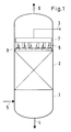
- an exchange column e.g. a rectification column 1
- packings 2 with an ordered structure in the mass transfer part such as those e.g. are known from CH-PS 398 503, arranged.
- Liquid inlets and outlets or gas inlets and outlets 3 to 6 are connected to the column.
- Liquid is fed through the feed line 3 into a distributor which has an upwardly open main channel 7.
- Subordinate channels 8, which are open at the top, are fed from this main channel and are equipped with baffles 9 according to the invention and explained in more detail with reference to the following drawings.
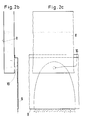
- a secondary duct 8 which in the exemplary embodiment is designed as a U-shaped channel, but which could also consist of a tube, is provided with a baffle 9.
- This baffle is bent upwards and firmly connected to one leg of the secondary duct. This has the advantage that no liquid can be carried upwards by the rising gas.
- the opposite sides of the gap can also be closed off by walls in order to prevent liquid from being carried upwards.
- An outlet opening 10 for the liquid is provided in the lower part of the leg of the secondary duct.
- the liquid emerges at a relatively high speed, impinges on the wall 9 and is distributed parabolically on it.
- the kinetic energy of the emerging liquid is used for the distribution.
- Baffle walls can of course also be arranged on both sides of a secondary duct.
- FIGS. 3a to 3c agree with FIGS. 2a to 2c that a screen wall 11 is additionally arranged on the lower part of the channel wall. Due to this measure, especially at high gas speeds, it is even better prevented that liquid can be entrained by the gas.
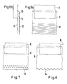
- FIGS. 4a to 4c corresponds to FIGS. 2a to 2c to the extent that two outlet openings 10a and 10b arranged one above the other are provided. This allows the device to span a wide range of stress conditions.
- FIGS. 5a to 5c The same applies to the embodiment shown in FIGS. 5a to 5c, with a screen wall 11 being attached to the channel wall 8 in accordance with FIGS. 3a to 3c.
- baffle walls 6a and 6b as well as in FIGS. 7 and 8, different embodiments for baffle walls are shown, with the baffle in the first case (FIGS. 6a and 6b) and a corrugation 12 and in the second case (FIG. 7) in the lower region a perforation 13 has an even better distribution of the liquid.
- a baffle 9 according to FIG. 8 is provided with teeth 14 at its lower end in order to bring about a better dripping of the liquid.
Landscapes
- Engineering & Computer Science (AREA)
- Chemical & Material Sciences (AREA)
- Chemical Kinetics & Catalysis (AREA)
- General Engineering & Computer Science (AREA)
- Thermal Sciences (AREA)
- Mechanical Engineering (AREA)
- Physics & Mathematics (AREA)
- Analytical Chemistry (AREA)
- General Chemical & Material Sciences (AREA)
- Oil, Petroleum & Natural Gas (AREA)
- Vaporization, Distillation, Condensation, Sublimation, And Cold Traps (AREA)
- Feeding, Discharge, Calcimining, Fusing, And Gas-Generation Devices (AREA)
- Physical Or Chemical Processes And Apparatus (AREA)
- Heat-Exchange Devices With Radiators And Conduit Assemblies (AREA)
Claims (6)
Applications Claiming Priority (2)
| Application Number | Priority Date | Filing Date | Title |
|---|---|---|---|
| CH782/87A CH671165A5 (fr) | 1987-03-02 | 1987-03-02 | |
| CH782/87 | 1987-09-29 |
Publications (3)
| Publication Number | Publication Date |
|---|---|
| EP0282753A1 EP0282753A1 (fr) | 1988-09-21 |
| EP0282753B1 true EP0282753B1 (fr) | 1992-05-20 |
| EP0282753B2 EP0282753B2 (fr) | 1995-06-28 |
Family
ID=4195056
Family Applications (1)
| Application Number | Title | Priority Date | Filing Date |
|---|---|---|---|
| EP88102405A Expired - Lifetime EP0282753B2 (fr) | 1987-03-02 | 1988-02-19 | Dispositif pour la distribution uniforme d'un liquide sur des parties d'échanges d'une colonne d'échange de matière et de chaleur |
Country Status (14)
| Country | Link |
|---|---|
| US (1) | US4855089A (fr) |
| EP (1) | EP0282753B2 (fr) |
| JP (1) | JP2683355B2 (fr) |
| CN (1) | CN1015233B (fr) |
| AR (1) | AR243674A1 (fr) |
| AU (1) | AU616170B2 (fr) |
| BR (1) | BR8800886A (fr) |
| CA (1) | CA1289459C (fr) |
| CH (1) | CH671165A5 (fr) |
| DE (1) | DE3871193D1 (fr) |
| ES (1) | ES2033351T5 (fr) |
| FI (1) | FI85818C (fr) |
| IN (1) | IN172304B (fr) |
| NO (1) | NO168748C (fr) |
Cited By (1)
| Publication number | Priority date | Publication date | Assignee | Title |
|---|---|---|---|---|
| US7125004B2 (en) | 2003-12-15 | 2006-10-24 | Koch-Glitsch, Lp | Liquid distributor for use in mass transfer column |
Families Citing this family (37)
| Publication number | Priority date | Publication date | Assignee | Title |
|---|---|---|---|---|
| CH674895A5 (fr) * | 1988-03-22 | 1990-07-31 | Kuehni Ag | |
| US4994210A (en) * | 1990-03-01 | 1991-02-19 | Koch Engineering Company, Inc. | High efficiency distributor for gas-liquid contact column and method of preparation and use |
| US5137214A (en) * | 1990-03-28 | 1992-08-11 | The Walt Disney Company | Method and apparatus for creating artificial rain |
| US5250234A (en) * | 1992-10-08 | 1993-10-05 | Koch Engineering Company, Inc. | Liquid distributor apparatus and method for high viscosity liquids |
| US5439620A (en) * | 1994-01-12 | 1995-08-08 | Mitsubishi Corporation | Liquid distributor to be used in substance and/or heat exchanging |
| EP0704232B1 (fr) * | 1994-09-28 | 1998-01-14 | Sulzer Chemtech AG | Dispositif de distribution de liquide pour colonne |
| DE19524774A1 (de) * | 1995-07-07 | 1997-01-09 | Montz Gmbh Julius | Ablaufzunge für Flüssigkeitsverteiler |
| US5906773A (en) * | 1997-07-30 | 1999-05-25 | Norton Company | Liquid distributor |
| ATE291948T1 (de) | 1998-11-30 | 2005-04-15 | Sulzer Chemtech Ag | Flüssigkeitsverteiler für packungskolonnen |
| EP1013324B1 (fr) * | 1998-11-30 | 2005-01-12 | Sulzer Chemtech AG | Colonne à contre-courant avec distributeur de liquide |
| EP1005889B1 (fr) * | 1998-11-30 | 2005-03-30 | Sulzer Chemtech AG | Distributeur de liquide pour des colonnes garnies |
| EP1153639B1 (fr) * | 2000-05-08 | 2008-07-16 | Sulzer Chemtech AG | Une colonne avec un plateau entre des parties de garnissage |
| ATE401114T1 (de) * | 2000-05-08 | 2008-08-15 | Sulzer Chemtech Ag | Kolonne mit einem boden zwischen füllkörperabschnitten |
| CA2338215C (fr) * | 2000-05-08 | 2004-09-14 | Sulzer Chemtech Ag | Piece guide pour faire devier un jet de liquide |
| US6722639B2 (en) | 2001-04-10 | 2004-04-20 | Koch-Glitsch, Lp | Liquid distributor in mass transfer column and method of installation and use |
| EP1572332B1 (fr) * | 2002-11-22 | 2013-01-30 | Fluor Corporation | Configurations et procedes pour paroi de descente a surface nervuree |
| EP1464370A1 (fr) * | 2003-03-17 | 2004-10-06 | Sulzer Chemtech AG | Distributeur de liquide |
| US8540218B2 (en) | 2007-04-27 | 2013-09-24 | Gtc Technology Us Llc | Fluid dispersion unit assembly and method |
| DE102007035639B3 (de) * | 2007-07-27 | 2009-02-26 | Outotec Oyj | Anlage zum Verteilen einer Flüssigkeit |
| US8517354B1 (en) | 2008-03-20 | 2013-08-27 | Gtc Technology Us Llc | Fluid dispersion unit with directional component vector |
| US9463397B2 (en) | 2008-04-04 | 2016-10-11 | Gtc Technology Us Llc | System and method for liquid distribution |
| US8517352B1 (en) | 2008-04-04 | 2013-08-27 | Gtc Technology Us Llc | Liquid distributor |
| US8678357B2 (en) | 2010-05-17 | 2014-03-25 | Gtc Technology Us, Llc | Fluid contactor-diffuser tray assembly |
| US8480062B2 (en) * | 2009-05-15 | 2013-07-09 | Gtc Technology Us, Llc | Activated hinge-joint |
| CN101837199A (zh) * | 2010-04-06 | 2010-09-22 | 浙江工业大学 | 一种线式液体分布器 |
| US9072986B2 (en) | 2011-02-23 | 2015-07-07 | Gtc Technology Us Llc | Method and apparatus for securing fractionation trays |
| JP2014514145A (ja) | 2011-03-31 | 2014-06-19 | エア プロダクツ アンド ケミカルズ インコーポレイテッド | 分離用カラム内の遮蔽 |
| US9597650B2 (en) | 2011-04-18 | 2017-03-21 | Gtc Technology Us Llc | System for improved reactant mixing and distribution |
| DE102012011553A1 (de) * | 2012-06-11 | 2013-12-12 | Rvt Process Equipment Gmbh | Niedriglastverteiler |
| US9089787B2 (en) * | 2012-12-14 | 2015-07-28 | Koch-Glitsch, Lp | Distributor in mass transfer column and method of use |
| CN103143183B (zh) * | 2013-03-25 | 2014-11-26 | 四川大学 | 膜厚可调的外环状弹性壁布膜器 |
| CN105264322B (zh) * | 2013-06-05 | 2018-06-22 | 开利公司 | 用于降膜式蒸发器的制冷剂分配器 |
| DE102014115077A1 (de) * | 2014-10-16 | 2016-04-21 | Rvt Process Equipment Gmbh | Flüssigkeitsverteiler einer verfahrenstechnischen Kolonne |
| EP3034980B1 (fr) * | 2014-12-17 | 2017-07-12 | Technische Universität Berlin | Dispositif pour le transfert de chaleur entre un liquide et un gaz et procédé pour faire fonctionner le dispositif |
| JP7015284B2 (ja) * | 2018-09-28 | 2022-02-02 | 株式会社デンソー | 水散布冷却装置 |
| EP3819025A1 (fr) | 2019-11-05 | 2021-05-12 | Hirschberg Engineering AG | Élément de distributeur ou de collecteur symétrique de type grille |
| EP3819014A1 (fr) | 2019-11-05 | 2021-05-12 | Hirschberg Engineering AG | Distributeur fractal de type grille ou élément de collecteur |
Family Cites Families (17)
| Publication number | Priority date | Publication date | Assignee | Title |
|---|---|---|---|---|
| US75238A (en) * | 1868-03-10 | Henry baldwin | ||
| US899899A (en) * | 1907-09-26 | 1908-09-29 | Hugo Petersen | Filling material for reaction-chambers. |
| US2295088A (en) * | 1939-03-24 | 1942-09-08 | William P Gruner | Means for distributing liquid refrigerants |
| FR979677A (fr) * | 1949-01-26 | 1951-04-30 | Réfrigérant d'eau à évaporation | |
| NL284535A (fr) | 1962-07-31 | |||
| US3290025A (en) * | 1965-11-19 | 1966-12-06 | Baltimore Aircoil Co Inc | Trough system for evaporative heat exchangers |
| DE1501406B1 (de) * | 1966-04-09 | 1970-07-30 | Maschb Ag Balcke | Fluessigkeitsverteilrinne fuer einen Kuehlturm |
| JPS4830412U (fr) * | 1971-08-18 | 1973-04-13 | ||
| US4159291A (en) * | 1977-08-16 | 1979-06-26 | Union Carbide Corporation | Outlet means for vapor-liquid contacting tray |
| DE2752391C2 (de) | 1977-11-24 | 1985-03-21 | Julius Montz Gmbh, 4010 Hilden | Verteilerboden |
| SU673322A1 (ru) * | 1978-02-03 | 1979-07-15 | Киевские Экспериментальные Мастерские Научно-Производственного Объединения "Химволокно" | Устройство дл нанесени композиций на издели |
| DE3013783A1 (de) * | 1979-11-08 | 1981-10-15 | Julius Montz Gmbh, 4010 Hilden | Fluessigkeitsverteiler fuer eine gegenstromkolonne |
| DE2945103C2 (de) * | 1979-11-08 | 1985-08-08 | Julius Montz Gmbh, 4010 Hilden | Flüssigkeitsverteiler für eine Gegenstromkolonne |
| JPS58137293U (ja) * | 1982-03-05 | 1983-09-14 | 高砂熱学工業株式会社 | 冷却塔 |
| US4476069A (en) * | 1983-02-23 | 1984-10-09 | The Dow Chemical Company | Liquid distributing apparatus for a liquid-vapor contact column |
| US4597916A (en) * | 1983-06-21 | 1986-07-01 | Glitsch, Inc. | Method of and apparatus for intermediate lamella vapor liquid contact |
| US4729857A (en) * | 1987-04-27 | 1988-03-08 | Glitsch, Inc. | Liquid distributor for packed tower |
-
1987
- 1987-03-02 CH CH782/87A patent/CH671165A5/de not_active IP Right Cessation
-
1988
- 1988-02-15 IN IN121DE1988 patent/IN172304B/en unknown
- 1988-02-18 FI FI880766A patent/FI85818C/fi not_active IP Right Cessation
- 1988-02-19 EP EP88102405A patent/EP0282753B2/fr not_active Expired - Lifetime
- 1988-02-19 DE DE8888102405T patent/DE3871193D1/de not_active Expired - Lifetime
- 1988-02-19 ES ES88102405T patent/ES2033351T5/es not_active Expired - Lifetime
- 1988-02-23 AR AR88310139A patent/AR243674A1/es active
- 1988-02-25 CN CN88100797A patent/CN1015233B/zh not_active Expired
- 1988-03-01 JP JP63045991A patent/JP2683355B2/ja not_active Expired - Lifetime
- 1988-03-01 CA CA000560160A patent/CA1289459C/fr not_active Expired - Lifetime
- 1988-03-01 BR BR8800886A patent/BR8800886A/pt not_active IP Right Cessation
- 1988-03-01 NO NO880912A patent/NO168748C/no unknown
- 1988-03-02 AU AU12567/88A patent/AU616170B2/en not_active Ceased
- 1988-03-02 US US07/163,371 patent/US4855089A/en not_active Expired - Lifetime
Cited By (1)
| Publication number | Priority date | Publication date | Assignee | Title |
|---|---|---|---|---|
| US7125004B2 (en) | 2003-12-15 | 2006-10-24 | Koch-Glitsch, Lp | Liquid distributor for use in mass transfer column |
Also Published As
| Publication number | Publication date |
|---|---|
| NO168748C (no) | 1992-04-01 |
| BR8800886A (pt) | 1988-10-11 |
| ES2033351T5 (es) | 1995-10-01 |
| AU616170B2 (en) | 1991-10-24 |
| CA1289459C (fr) | 1991-09-24 |
| FI85818B (fi) | 1992-02-28 |
| FI880766A (fi) | 1988-09-03 |
| NO880912L (no) | 1988-09-05 |
| FI880766A0 (fi) | 1988-02-18 |
| IN172304B (fr) | 1993-06-05 |
| JP2683355B2 (ja) | 1997-11-26 |
| AU1256788A (en) | 1988-09-01 |
| JPS63243689A (ja) | 1988-10-11 |
| EP0282753A1 (fr) | 1988-09-21 |
| EP0282753B2 (fr) | 1995-06-28 |
| DE3871193D1 (de) | 1992-06-25 |
| CN1015233B (zh) | 1992-01-01 |
| FI85818C (fi) | 1992-06-10 |
| CN88100797A (zh) | 1988-09-14 |
| US4855089A (en) | 1989-08-08 |
| NO168748B (no) | 1991-12-23 |
| NO880912D0 (no) | 1988-03-01 |
| AR243674A1 (es) | 1993-08-31 |
| CH671165A5 (fr) | 1989-08-15 |
| ES2033351T3 (es) | 1993-03-16 |
Similar Documents
| Publication | Publication Date | Title |
|---|---|---|
| EP0282753B1 (fr) | Dispositif pour la distribution uniforme d'un liquide sur des parties d'échanges d'une colonne d'échange de matière et de chaleur | |
| EP0112978B1 (fr) | Distributeur de liquide pour une colonne d'échange de masse et ou de chaleur | |
| EP0013284B1 (fr) | Dispositif pour la distribution de liquides dans des colonnes d'échange de masse et de chaleur | |
| EP0151693B1 (fr) | Colonne d'échange de matière | |
| DE1519711C3 (de) | Zuführen eines Dampf-Flüssigkeits-Gemisches in Stoffaustauschkolonnen | |
| EP0118029B1 (fr) | Dispositif pour la distribution gravimétrique de liquide pour une colonne d'échange de masse et de chaleur | |
| CH642566A5 (de) | Trogartige vorrichtung zum sammeln und verteilen der fluessigkeit in einer gegenstromkolonne. | |
| DE3907436C2 (de) | Flüssigkeitsverteiler für Stoff- und Wärmeaustauschkolonnen | |
| DE2248273A1 (de) | Waermeaustauscher und verfahren zu dessen anwendung | |
| DE3141930C2 (de) | Verteilerboden für eine Austauschkolonne | |
| DE60222224T2 (de) | Flüssigkeitsverteiler mit innerem Leitelement | |
| CH663904A5 (de) | Fluessigkeitsverteiler fuer eine stoffaustauschkolonne. | |
| DE1619902B2 (de) | Vorrichtung zum abscheiden von fluessigkeit aus einem gas foermigen medium | |
| EP0273191B1 (fr) | Distributeur de liquides pour des colonnes à transfert de masse et de chaleur | |
| EP0264581A1 (fr) | Dispositif de distribution des liquides pour des colonnes de transfert de matière et de chaleur | |
| DE10026064C1 (de) | Flüssigkeitsverteilerkörper für Stoff- und Wärmeaustauschkolonnen | |
| DE2554071C3 (de) | Verteilervorrichtung für Fallstromverdampfer | |
| EP0232759B1 (fr) | Distributeur à ajutage tubulaire pour une phase dispersée dans une colonne d'extraction de liquide-liquide, dans une colonne à bulles de gaz-liquide et dans une colonne de réaction | |
| EP1588749B1 (fr) | Dispositif d'entrée d'un fluide pour un appareil, en particulier pour une colonne | |
| DD275619A1 (de) | Fluessigkeitsverteilereinrichtung mit dampfabfuehrungssektion fuer gegenstromfallfilterverdampfer | |
| DD227332B1 (de) | Fluessigkeitsverteilvorrichtung auf senkrechte rohrbuendel, insbesondere fuer fallfilmapparate | |
| DE10210683B4 (de) | Einsatzelement für Flüssigkeitsverteilerkörper für Stoff- und Wärmeaustauschkolonnen | |
| DE2923198B2 (de) | Flüssigkeitsverteiler für Stoffaustauschkolonnen | |
| DE1619902C (de) | Vorrichtung zum Abscheiden von Flus sigkeit aus einem gasförmigen Medium | |
| DE8300693U1 (de) | Flüssigkeitsverteiler für eine Stoff- und Wärmeaustauschkolonne |
Legal Events
| Date | Code | Title | Description |
|---|---|---|---|
| PUAI | Public reference made under article 153(3) epc to a published international application that has entered the european phase |
Free format text: ORIGINAL CODE: 0009012 |
|
| AK | Designated contracting states |
Kind code of ref document: A1 Designated state(s): BE DE ES FR GB IT NL SE |
|
| 17P | Request for examination filed |
Effective date: 19890308 |
|
| 17Q | First examination report despatched |
Effective date: 19901203 |
|
| ITF | It: translation for a ep patent filed |
Owner name: ING. ZINI MARANESI & C. S.R.L. |
|
| GRAA | (expected) grant |
Free format text: ORIGINAL CODE: 0009210 |
|
| AK | Designated contracting states |
Kind code of ref document: B1 Designated state(s): BE DE ES FR GB IT NL SE |
|
| REF | Corresponds to: |
Ref document number: 3871193 Country of ref document: DE Date of ref document: 19920625 |
|
| GBT | Gb: translation of ep patent filed (gb section 77(6)(a)/1977) | ||
| PLBI | Opposition filed |
Free format text: ORIGINAL CODE: 0009260 |
|
| 26 | Opposition filed |
Opponent name: FIRMA J. MONTZ GMBH Effective date: 19920701 |
|
| ET | Fr: translation filed | ||
| NLR1 | Nl: opposition has been filed with the epo |
Opponent name: FIRMA J. MONTZ GMBH |
|
| PLAB | Opposition data, opponent's data or that of the opponent's representative modified |
Free format text: ORIGINAL CODE: 0009299OPPO |
|
| EAL | Se: european patent in force in sweden |
Ref document number: 88102405.3 |
|
| R26 | Opposition filed (corrected) |
Opponent name: FIRMA J. MONTZ GMBH Effective date: 19920701 |
|
| PUAH | Patent maintained in amended form |
Free format text: ORIGINAL CODE: 0009272 |
|
| STAA | Information on the status of an ep patent application or granted ep patent |
Free format text: STATUS: PATENT MAINTAINED AS AMENDED |
|
| 27A | Patent maintained in amended form |
Effective date: 19950628 |
|
| AK | Designated contracting states |
Kind code of ref document: B2 Designated state(s): BE DE ES FR GB IT NL SE |
|
| GBTA | Gb: translation of amended ep patent filed (gb section 77(6)(b)/1977) |
Effective date: 19950628 |
|
| ET3 | Fr: translation filed ** decision concerning opposition | ||
| NLR2 | Nl: decision of opposition | ||
| ITF | It: translation for a ep patent filed |
Owner name: ING. ZINI MARANESI & C. S.R.L. |
|
| REG | Reference to a national code |
Ref country code: ES Ref legal event code: DC2A Kind code of ref document: T5 Effective date: 19951001 |
|
| NLR3 | Nl: receipt of modified translations in the netherlands language after an opposition procedure | ||
| PGFP | Annual fee paid to national office [announced via postgrant information from national office to epo] |
Ref country code: ES Payment date: 19990218 Year of fee payment: 12 |
|
| PGFP | Annual fee paid to national office [announced via postgrant information from national office to epo] |
Ref country code: BE Payment date: 20000208 Year of fee payment: 13 |
|
| PGFP | Annual fee paid to national office [announced via postgrant information from national office to epo] |
Ref country code: SE Payment date: 20010205 Year of fee payment: 14 |
|
| PG25 | Lapsed in a contracting state [announced via postgrant information from national office to epo] |
Ref country code: ES Free format text: LAPSE BECAUSE OF NON-PAYMENT OF DUE FEES Effective date: 20010220 |
|
| PG25 | Lapsed in a contracting state [announced via postgrant information from national office to epo] |
Ref country code: BE Free format text: LAPSE BECAUSE OF NON-PAYMENT OF DUE FEES Effective date: 20010228 |
|
| BERE | Be: lapsed |
Owner name: GEBRUDER SULZER A.G. Effective date: 20010228 |
|
| REG | Reference to a national code |
Ref country code: GB Ref legal event code: IF02 |
|
| PG25 | Lapsed in a contracting state [announced via postgrant information from national office to epo] |
Ref country code: SE Free format text: LAPSE BECAUSE OF NON-PAYMENT OF DUE FEES Effective date: 20020220 |
|
| EUG | Se: european patent has lapsed |
Ref document number: 88102405.3 |
|
| REG | Reference to a national code |
Ref country code: ES Ref legal event code: FD2A Effective date: 20020916 |
|
| PGFP | Annual fee paid to national office [announced via postgrant information from national office to epo] |
Ref country code: NL Payment date: 20070213 Year of fee payment: 20 |
|
| PGFP | Annual fee paid to national office [announced via postgrant information from national office to epo] |
Ref country code: DE Payment date: 20070216 Year of fee payment: 20 Ref country code: GB Payment date: 20070216 Year of fee payment: 20 |
|
| PGFP | Annual fee paid to national office [announced via postgrant information from national office to epo] |
Ref country code: IT Payment date: 20070626 Year of fee payment: 20 |
|
| REG | Reference to a national code |
Ref country code: GB Ref legal event code: PE20 |
|
| NLV7 | Nl: ceased due to reaching the maximum lifetime of a patent |
Effective date: 20080219 |
|
| PG25 | Lapsed in a contracting state [announced via postgrant information from national office to epo] |
Ref country code: NL Free format text: LAPSE BECAUSE OF EXPIRATION OF PROTECTION Effective date: 20080219 |
|
| PGFP | Annual fee paid to national office [announced via postgrant information from national office to epo] |
Ref country code: FR Payment date: 20070212 Year of fee payment: 20 |
|
| PG25 | Lapsed in a contracting state [announced via postgrant information from national office to epo] |
Ref country code: GB Free format text: LAPSE BECAUSE OF EXPIRATION OF PROTECTION Effective date: 20080218 |