EP0280995A2 - Récipient transportable avec verrouillage, en particulier valises, serviettes d'affaires ou analogues - Google Patents
Récipient transportable avec verrouillage, en particulier valises, serviettes d'affaires ou analogues Download PDFInfo
- Publication number
- EP0280995A2 EP0280995A2 EP88102621A EP88102621A EP0280995A2 EP 0280995 A2 EP0280995 A2 EP 0280995A2 EP 88102621 A EP88102621 A EP 88102621A EP 88102621 A EP88102621 A EP 88102621A EP 0280995 A2 EP0280995 A2 EP 0280995A2
- Authority
- EP
- European Patent Office
- Prior art keywords
- handle
- container
- container according
- lockable
- portable container
- Prior art date
- Legal status (The legal status is an assumption and is not a legal conclusion. Google has not performed a legal analysis and makes no representation as to the accuracy of the status listed.)
- Withdrawn
Links
Images


Classifications
-
- A—HUMAN NECESSITIES
- A45—HAND OR TRAVELLING ARTICLES
- A45C—PURSES; LUGGAGE; HAND CARRIED BAGS
- A45C13/00—Details; Accessories
- A45C13/10—Arrangement of fasteners
-
- B—PERFORMING OPERATIONS; TRANSPORTING
- B65—CONVEYING; PACKING; STORING; HANDLING THIN OR FILAMENTARY MATERIAL
- B65D—CONTAINERS FOR STORAGE OR TRANSPORT OF ARTICLES OR MATERIALS, e.g. BAGS, BARRELS, BOTTLES, BOXES, CANS, CARTONS, CRATES, DRUMS, JARS, TANKS, HOPPERS, FORWARDING CONTAINERS; ACCESSORIES, CLOSURES, OR FITTINGS THEREFOR; PACKAGING ELEMENTS; PACKAGES
- B65D55/00—Accessories for container closures not otherwise provided for
- B65D55/02—Locking devices; Means for discouraging or indicating unauthorised opening or removal of closure
-
- E—FIXED CONSTRUCTIONS
- E05—LOCKS; KEYS; WINDOW OR DOOR FITTINGS; SAFES
- E05B—LOCKS; ACCESSORIES THEREFOR; HANDCUFFS
- E05B65/00—Locks or fastenings for special use
- E05B65/52—Other locks for chests, boxes, trunks, baskets, travelling bags, or the like
-
- E—FIXED CONSTRUCTIONS
- E05—LOCKS; KEYS; WINDOW OR DOOR FITTINGS; SAFES
- E05C—BOLTS OR FASTENING DEVICES FOR WINGS, SPECIALLY FOR DOORS OR WINDOWS
- E05C9/00—Arrangements of simultaneously actuated bolts or other securing devices at well-separated positions on the same wing
- E05C9/04—Arrangements of simultaneously actuated bolts or other securing devices at well-separated positions on the same wing with two sliding bars moved in opposite directions when fastening or unfastening
- E05C9/042—Arrangements of simultaneously actuated bolts or other securing devices at well-separated positions on the same wing with two sliding bars moved in opposite directions when fastening or unfastening with pins engaging slots
-
- E—FIXED CONSTRUCTIONS
- E05—LOCKS; KEYS; WINDOW OR DOOR FITTINGS; SAFES
- E05B—LOCKS; ACCESSORIES THEREFOR; HANDCUFFS
- E05B13/00—Devices preventing the key or the handle or both from being used
- E05B13/002—Devices preventing the key or the handle or both from being used locking the handle
-
- E—FIXED CONSTRUCTIONS
- E05—LOCKS; KEYS; WINDOW OR DOOR FITTINGS; SAFES
- E05B—LOCKS; ACCESSORIES THEREFOR; HANDCUFFS
- E05B13/00—Devices preventing the key or the handle or both from being used
- E05B13/005—Disconnecting the handle
-
- E—FIXED CONSTRUCTIONS
- E05—LOCKS; KEYS; WINDOW OR DOOR FITTINGS; SAFES
- E05B—LOCKS; ACCESSORIES THEREFOR; HANDCUFFS
- E05B13/00—Devices preventing the key or the handle or both from being used
- E05B13/10—Devices preventing the key or the handle or both from being used formed by a lock arranged in the handle
- E05B13/103—Combination lock
-
- E—FIXED CONSTRUCTIONS
- E05—LOCKS; KEYS; WINDOW OR DOOR FITTINGS; SAFES
- E05B—LOCKS; ACCESSORIES THEREFOR; HANDCUFFS
- E05B17/00—Accessories in connection with locks
- E05B17/0025—Devices for forcing the wing firmly against its seat or to initiate the opening of the wing
- E05B17/0033—Devices for forcing the wing firmly against its seat or to initiate the opening of the wing for opening only
-
- E—FIXED CONSTRUCTIONS
- E05—LOCKS; KEYS; WINDOW OR DOOR FITTINGS; SAFES
- E05B—LOCKS; ACCESSORIES THEREFOR; HANDCUFFS
- E05B63/00—Locks or fastenings with special structural characteristics
- E05B63/18—Locks or fastenings with special structural characteristics with arrangements independent of the locking mechanism for retaining the bolt or latch in the retracted position
- E05B63/20—Locks or fastenings with special structural characteristics with arrangements independent of the locking mechanism for retaining the bolt or latch in the retracted position released automatically when the wing is closed
-
- E—FIXED CONSTRUCTIONS
- E05—LOCKS; KEYS; WINDOW OR DOOR FITTINGS; SAFES
- E05C—BOLTS OR FASTENING DEVICES FOR WINGS, SPECIALLY FOR DOORS OR WINDOWS
- E05C9/00—Arrangements of simultaneously actuated bolts or other securing devices at well-separated positions on the same wing
- E05C9/04—Arrangements of simultaneously actuated bolts or other securing devices at well-separated positions on the same wing with two sliding bars moved in opposite directions when fastening or unfastening
-
- Y—GENERAL TAGGING OF NEW TECHNOLOGICAL DEVELOPMENTS; GENERAL TAGGING OF CROSS-SECTIONAL TECHNOLOGIES SPANNING OVER SEVERAL SECTIONS OF THE IPC; TECHNICAL SUBJECTS COVERED BY FORMER USPC CROSS-REFERENCE ART COLLECTIONS [XRACs] AND DIGESTS
- Y10—TECHNICAL SUBJECTS COVERED BY FORMER USPC
- Y10T—TECHNICAL SUBJECTS COVERED BY FORMER US CLASSIFICATION
- Y10T70/00—Locks
- Y10T70/50—Special application
- Y10T70/5009—For portable articles
- Y10T70/5031—Receptacle
- Y10T70/5058—Trunk and/or suitcase
- Y10T70/5062—Projecting fixed or movable lug type
-
- Y—GENERAL TAGGING OF NEW TECHNOLOGICAL DEVELOPMENTS; GENERAL TAGGING OF CROSS-SECTIONAL TECHNOLOGIES SPANNING OVER SEVERAL SECTIONS OF THE IPC; TECHNICAL SUBJECTS COVERED BY FORMER USPC CROSS-REFERENCE ART COLLECTIONS [XRACs] AND DIGESTS
- Y10—TECHNICAL SUBJECTS COVERED BY FORMER USPC
- Y10T—TECHNICAL SUBJECTS COVERED BY FORMER US CLASSIFICATION
- Y10T70/00—Locks
- Y10T70/50—Special application
- Y10T70/5611—For control and machine elements
- Y10T70/5757—Handle, handwheel or knob
- Y10T70/5765—Rotary or swinging
- Y10T70/577—Locked stationary
- Y10T70/5783—Combination lock
Definitions
- the invention relates to a lockable portable container, in particular a travel case, a board case, a briefcase or the like, with a handle movably attached to it.
- the present invention in particular solves the problem of providing a lockable, portable container of the type mentioned at the outset, which can be opened and closed by its user in a particularly practical and convenient manner.
- a coupling device which converts the handle movement into an unlocking or locking and / or opening or closing movement of the container locking mechanism, which is provided as a connection between the handle and the container locking mechanism, and a transmission which locks the handle movement or its transmission on the container locking mechanism lifting unlocking and / or opening locking device.
- an unlocking and / or opening locking device which is conveniently preferably provided directly on the handle, so that the container locking mechanism, for example one or two case locks, opens, preferably opens, so that the user only has to fold up the lid of the portable container, provided that it is not provided with an elastic spring-up device which allows the lid of the portable container to open by itself.
- the handle of the portable container according to the invention can be moved in a variety of ways, for example the crosspiece of a U-shaped handle, the two legs of which are attached to the portable container, can be designed to be displaceable towards or away from the container, or this crosspiece can be slidably mounted together with the legs parallel to the side of the container to which the handle is attached.
- a particularly practical and structurally advantageous embodiment of the lockable portable container according to the invention is obtained, however, if the handle is pivotally attached to the container and the pivoting mechanism is connected via the coupling device to the container locking mechanism for its actuation.
- the design of the lockable portable container can be such that the handle has at least two legs and is pivotally attached to the container with its one leg.
- the handle is preferably attached to the container so as to be pivotable about the longitudinal axis of one leg.
- a particularly practical and advantageous embodiment of the invention results if the handle is L-shaped or U-shaped and is attached to the container so as to be pivotable about the longitudinal axis of an L-leg or U-leg.
- This longitudinal axis of the leg, about which the handle is pivotably attached to the container can preferably run perpendicular to the side of the container to which the handle is attached.
- the other L-leg or the crossbar of a U-shaped handle can be pivoted in a practical manner parallel to the side of the container on which the handle is mounted.
- a U-shaped handle is attached to the container in the aforementioned manner, then it can be further provided on the container such that the U-shaped handle with the other U-leg, which is parallel to the U-leg pivotally attached to the container runs, can be locked or locked by means of a latching mechanism on the container, so that this prevents undesired pivoting of the handle when the container is being carried normally.
- the lockable portable container so that the U-shaped handle on the free end of the other U-leg, which is parallel to the pivotally attached U-leg, on the container in a guide, for example as in a guide groove or joint serving as a counter bearing, which preferably has one or two stops which limit the pivoting movement in one pivoting direction or in both pivoting directions. This prevents an undesirably wide and impractical pivoting of the handle, for example.
- the unlocking and / or opening locking device can be designed as a releasable movement lock for the handle, so that it secures the same against pivoting when the handle is pivotally attached to the container.
- the above-mentioned latching mechanism can serve as such a movement lock, but it is particularly preferred to use such a movement or To provide swivel lock in the movement or swivel mechanism of the handle, as a result of which the movement lock is integrated particularly well into the overall structure.
- This movement lock can be released or unlocked by means of an actuating element, the actuating element being provided on or in the handle or being arranged on or in the latching mechanism.
- the lockable portable container according to the invention is preferably designed in such a way that the actuating element is or comprises a push button and / or a lock, in particular a cylinder or combination lock.
- the actuating element is a push button which can be locked by the lock, in particular the cylinder or combination lock, which can be done in a simple manner, for example, by the fact that the cylinder or Combination lock actuated locking element, when the cylinder or combination lock is not open, into the displacement path of the latter as a displacement lock protrudes and is moved out of this displacement path by opening the latter.
- a particularly compact and highly integrated structure is achieved in that the cylinder or combination lock and / or the push button is provided on or in the handle.
- the cylinder or combination lock and / or the push button can also be attached to or in the latching mechanism.
- the aforementioned latching mechanism can also be provided only as an auxiliary mechanism for moving or pivoting the handle into the locking position, in which it can be completely counteracted by a detachable movement lock provided in the handle itself or in its movement or pivoting mechanism Moving or pivoting is locked.
- a particularly advantageous embodiment of the unlocking and / or opening locking device is characterized in that the push button is provided on a pivotably mounted lever arm, the pivoting movement of which can be locked by the cylinder or combination lock and which acts on a locking bolt which is located on the container Locking and guiding member, in particular a guide and bearing plate, cooperates.
- the coupling device is preferably designed in such a way that it comprises a bolt which is attached to the handle in a rotationally fixed manner and, by means of its rotation, movable actuating elements, in particular displaceable slides, for actuating the container locking mechanism.
- a preferred embodiment of the container locking mechanism is characterized in that it has a displaceable Ver by the coupling device has sliding plate, which cooperates with an ejection lever which is pivotable about an axis fixed with respect to the container and is acted upon by a compression spring in the sense of pushing away a hook attached to the cover from the container, a locking projection being provided for the hook on the sliding plate and the latter also has a release projection for the ejection lever, which secures the ejection lever against pivoting movement in the locked position of the container locking mechanism and secures the displacement plate in the unlocked position of the container locking mechanism against displacement into the locked position.
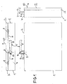
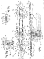
- the lockable container 1 shown in FIG. 1 is in the present case a briefcase or board case which has a lid 2 which is attached to the actual container 1 at point 3 by an invisible hinge.
- This handle 5 is L-shaped and with its one leg 6 pivotally attached to the container 1, namely the pivotable attachment is such that the handle 5 is pivotable about the longitudinal axis 7 of the leg 6, so that its other L-leg 8 is pivoted parallel to the longitudinal narrow side 4.
- the lockable portable container 1 also has a container locking mechanism 9, which in the present case consists of two briefcase locks which are not visible from the outside and are therefore only indicated in dashed lines.
- this container locking mechanism 9 When this container locking mechanism 9 is opened, the lid 2 is released so that it is pivoted in the direction of arrow 10 around the hinge located at point 3 and container 1 can thus be opened.
- the container 1 is further provided with a coupling device 11 indicated by dash-dotted lines, which converts the pivoting movement of the handle 5 into an unlocking or locking and / or opening or closing movement of the container locking mechanism 9 and therefore as a connection between the handle 5 and the Container locking mechanism 9 is provided.
- a coupling device 11 indicated by dash-dotted lines, which converts the pivoting movement of the handle 5 into an unlocking or locking and / or opening or closing movement of the container locking mechanism 9 and therefore as a connection between the handle 5 and the Container locking mechanism 9 is provided.
- coupling devices 11 which are available to any person skilled in the art as mechanical elementary devices which are capable of transmitting the pivoting movement of the handle to the container locking mechanism 9 in such a way that the container locking mechanism 9 is thereby unlocked or locked and / or opened or is closed.
- a longitudinally displaceable rod is suitable as the coupling device 11, which is articulated at one end to an arm which is fixedly attached to the axis of rotation of the handle 5, and at the other end articulated on a plate or tongue-shaped or in any other way trained unlocking or locking and / or opening or closing element is attached, as is provided for the unlocking or locking and / or opening or closing of conventional case locks.
- the portable container 1 which, as already mentioned, is a board case, can be closed and / or opened by simply pivoting the handle 5 about the longitudinal axis 7 of the leg 6, which is much more practical and convenient than the container locking mechanism 9, which in the present case consists of two suitcase locks, which would have to be opened or closed individually, to be operated directly separately.
- Opening locking device 12 is provided, which is only indicated by dashed lines, since it, for example is arranged either in the handle or in the vicinity of the handle in the container 1 or in the wall thereof.
- this unlocking and / or opening blocking device can either be a device which locks the handle 5 against a pivoting movement about the longitudinal axis 7 or the operative connection between the pivoting movement of the handle 5 and the coupling device 11 and / or the container locking mechanism 9 at times interrupts or cancels. Since a person skilled in the art from elementary mechanics has a large number of possible devices with which the pivotability of a part is locked or the mechanical efficacy bond between two coupled parts can be temporarily suspended or interrupted, it is not necessary here to describe different embodiments of the unlocking and / or opening locking device.
- a bolt that can be displaced against spring force can be provided in the fixed part of the pivot bearing of the handle 5, which bolt extends into a radial opening in the axis of the handle 5 that is rotatable in this pivot bearing intervene and thus block the pivoting movement and can be pushed out of this radial recess so far by an axially displaceable against spring force within the axis of rotation that it releases the handle 5 for a pivoting movement.
- a corresponding device which interrupts the transmission of the pivoting movement of the handle 5 to the coupling device 11, can be designed in the coupling device given above as an example similar to the above device for locking the handle 5 by the lever mentioned above, which on the Axis of rotation of the handle 5 is attached, is not attached directly to this axis of rotation, but rather via a ring rotatably mounted on the axis of rotation, which by means of a device of the aforementioned type by means of a first and second bolt, as just described, on the axis of rotation of the handle 5 can be locked and unlocked from this axis of rotation.
- a push button 13 is provided in the pivotably attached to the container 1 leg 6 of the handle 5, which acts against spring force can be depressed and thereby a pivoting of the handle 5 or a transmission of the pivoting movement of the handle 5 on the container locking mechanism 9.
- the push button 13 can, for example, be arranged in such a way that it presses the above-mentioned second bolt of the unlocking and / or opening locking device specified in two examples above when it is actuated.
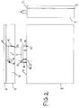
- a further embodiment of a lockable portable container which is shown in FIG. 2, differs from the embodiment of FIG. 1 essentially only in that here the handle 5 is U-shaped and at the free end of that U-leg 14, which is parallel to the pivotable U-leg 6 attached to the container 1, is guided on the container 1 in a guide 15.
- This guide 15, which can be a guide groove or a guide joint for the free end 16, has two stops 17 and 18 which limit the pivoting movement of the handle 5 in the two pivoting directions. These stops can be end walls of the guide 15 at its two longitudinal ends, for example.
- FIG. 2 For the rest, with regard to the description of the embodiment according to FIG. 2, reference is made to the description of the embodiment according to FIG. 1, it also being pointed out that some parts which are shown in FIG. 1 are shown in FIG. 2 for reasons of simplification of the Representation are not shown, although they are also present in the embodiment according to FIG. 2, in particular the container locking mechanism 9 and the coupling device 11.
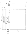
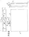
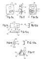
- FIGS. 3 to 6 which of course also include a container locking mechanism 9 and a coupling device 11 and an unlocking and / or opening locking device 12, even if these devices to simplify the drawing, not particularly Darge are because they have already been explained with reference to FIG. 1. Therefore, in the following explanation of the embodiments according to FIGS. 3 to 6, essentially only peculiarities compared to the embodiment according to FIG. 1 are described, but otherwise reference is made to the explanation of FIG.
- the U-shaped handle 5 can be locked or locked by means of the U-leg 14, which runs parallel to the U-leg 6 pivotally attached to the container 1, by a latching mechanism on the container 1, wherein the pivoting movement of the handle 5 is indicated by the arrow 20 in Fig. 4, by means of which the lid 2 is released so that it can be folded up in the direction of arrow 10.
- An example of one of many possible snap-in mechanisms that are available to the person skilled in the art as elementary mechanical devices is a ball that is elastically pressed into a recess that is located in the free end 16 of the U-leg 14, this ball also can be locked by a suitable device, which is referred to here as an unlocking and / or opening locking device or corresponds to the above-mentioned unlocking and / or opening locking device, so that an unintentional pivoting movement of the handle 5 can be prevented.
- This unlocking and / or opening locking device can in turn be actuated by a push button so that the handle 5 is released for a pivoting movement.
- the push button 13 lockable by a combination lock 21, so that it is unlocked only by corresponding actuation of the combination lock 21 and can only be depressed according to the arrow 22 (see FIG. 6) in order to release the handle 5 for a pivoting movement in the direction of the arrow 20 to reach.
- the combination lock 21 is provided in the handle 5, preferably in the leg 6 thereof, which results in a compact and very clear structure.
- the combination lock can, for example, be installed laterally in the leg 6, as is the case in the embodiment according to FIG. 6, or, as is the case in the embodiment according to FIG. 5, in the upper side of the leg 6 .
- FIGS. 7 to 12 are in one of the containers according to FIGS. 1 to 6, in particular in one of the containers according to the figures 1, 5 and 6 can be installed.
- the combination lock 21 in the present case comprises three number wheels 27a, 27b and 27c and associated cam wheels 28a, 28b and 28c, but it can also comprise two number wheels, as indicated in FIG. 6, or three or more number wheels. In addition, other symbols can be provided on the number wheels instead of numbers.
- This combination lock 21 is constructed in a manner known per se in such a way that its axis 25 can only be displaced in the longitudinal direction downwards against the force of the compression spring 26 if the combination of numbers or symbols opening the combination lock by means of the number wheels 27a, 27b and 27c is set. If this is the case, the lever arm 22 can be pivoted downward about its axis 23 by a downward pressure on the push button 13.
- a locking bolt 30 is in the pivoting path of the lever arm 22, and this thickened end 29 is pressed by means of a return spring 31 against the underside of the lever arm 22.
- the Locking bolt 30 can be moved downwards in its longitudinal direction, in this case parallel to the axis 25 of the combination lock 21, and this downward displacement of the locking bolt 30 is brought about by pressing the push button 13 by means of the lever arm 22 when its pivoting movement is released by the combination lock 21 is.
- the opening 33 also has a lower region which merges into a wider guideway 37 for the end 32 which runs parallel to the guideway 36.
- the guide and bearing plate 34 also has a bearing sleeve 38 in which a pivot 39 is rotatable is mounted, which in turn is provided in a fixed manner in the handle 5.
- a threaded sleeve 40 through which a long screw 41 is screwed from above and a short screw 42 is screwed from below, runs through this pivot pin 39 concentrically to the longitudinal axis 7, with a bolt 44 at the lower end by means of the short screw 42 and a washer 43 of the pivot 39 is attached.
- the latch 44 as shown in FIG. 10, is generally ring-shaped and has two inner projections 45 and two outer projections 46a and 46b.
- the inner projections 45 engage in two grooves which are provided at the lower end of the pivot 39, as a result of which the bolt 44 is connected to the pivot 39 in a rotationally fixed manner. Since the pivot 39 is in turn inserted into the handle 5 in a rotationally fixed manner, the bolt 44 shown in FIG. 10 in supervision is also rotated when the handle 5 is rotated about the longitudinal axis.
- the bolt 44 already forms part of the coupling device 11, through which the rotational movement of the handle 5 is transmitted to the container locking mechanism 9.
- a longitudinal end 47a and 47b of a slide 48a and 48b in the rotation range of each of the two outer projections 46a and 46b.
- These two slides 48a and 48b are displaceable in their longitudinal direction in the guide 49 formed by grooves of a mounting rail 50, which in turn is provided within the longitudinal narrow side 4 so that it extends with its longitudinal direction in the longitudinal direction of this longitudinal narrow side 4.
- the container locking mechanism 9 which will now be described in more detail with reference to FIG. 8, essentially consists of a displacement plate 53, a spring 54 which is U-shaped in the present example, an ejection lever 55 and a locking hook 56, the parts of which the first three on the inside Longitudinal narrow side 4 of the container 1 are provided, while the locking hook 56 is provided on the lid 2.
- the displacement plate 53 is mounted in a groove-shaped guide 57 (see FIG. 11) of the mounting rail 50 so as to be displaceable in the longitudinal direction and has a locking projection 58 which runs perpendicular to the plane of the drawing in FIG. 8 and which engages in the opening 59 of the hook 56 and by displacing the displacement plate 53. 8 to the right, can be moved out of this opening 59, as a result of which the cover 2 is released for opening.
- the sliding plate at the right end has a release protruding from the plane of the drawing in FIG projection 60 and at its left end a stop projection 61, which also protrudes from the plane of the drawing, and a engagement projection 62 directed to the left.
- the engagement projection 62 engages in the recess 63 in which the return spring 51 is located; the operation of the other two projections 60 and 61 is explained below.
- the ejection lever 55 is rotatably mounted about an axis 64 which is stationary relative to the mounting rail 50 fixedly attached to the longitudinal narrow side 4 of the container 1.
- This ejection lever 55 is located on one side 65 in contact with the free end of the hook 56 and is subjected to a prestress by the spring 54, which tends to push the ejection lever 55 towards the hook 56, that is to say in FIG Clockwise to twist.
- the ejection lever 55 In the locking position of the container locking mechanism 9 shown in FIG. 8, however, the ejection lever 55 is prevented from rotating by the fact that a lug 66 provided thereon is in engagement with the release projection 60 of the displacement plate 53.
- the spring 54 which presses the ejection lever 55 on one side in the sense of the aforementioned rotational movement, is supported on the other side on the stop projection 61.
- the stop projection 61 is in contact with the longitudinal end 52 of the slider 48b.
- the handle 5 can be pivoted back into the rest position, in which it can be locked by means of the locking bolt 30.
- the slides 48a and 48b are pushed back into the position shown in FIG. 8 by their return springs, such as the return spring 51 for the slider 48b.
- the slide plate 53 cannot follow this movement because it is displaced to the left (based on the view in FIG. 8) by the right-hand side 67 of the nose 66, which coincides with the left-hand side 68 of the release projection 60 engaged, is prevented. Only when the hook 56 is brought back into the position shown in FIG.
- the combination lock 21 When the combination lock 21 is brought into the open state and the push button 13 is pressed down, the combination of numbers or symbols required to open the combination lock 21 can be changed by turning the number wheels 27a, 27b and 27c.
- the handle described can also be used as a door handle, window handle, etc.
Landscapes
- Engineering & Computer Science (AREA)
- Mechanical Engineering (AREA)
- Purses, Travelling Bags, Baskets, Or Suitcases (AREA)
- Closures For Containers (AREA)
Applications Claiming Priority (2)
| Application Number | Priority Date | Filing Date | Title |
|---|---|---|---|
| DE3706723 | 1987-03-02 | ||
| DE19873706723 DE3706723A1 (de) | 1987-03-02 | 1987-03-02 | Verriegelbarer, tragbarer behaelter, insbesondere reisekoffer, boardcase, aktenkoffer oder dergleichen |
Publications (2)
| Publication Number | Publication Date |
|---|---|
| EP0280995A2 true EP0280995A2 (fr) | 1988-09-07 |
| EP0280995A3 EP0280995A3 (fr) | 1989-07-12 |
Family
ID=6322127
Family Applications (1)
| Application Number | Title | Priority Date | Filing Date |
|---|---|---|---|
| EP88102621A Withdrawn EP0280995A3 (fr) | 1987-03-02 | 1988-02-23 | Récipient transportable avec verrouillage, en particulier valises, serviettes d'affaires ou analogues |
Country Status (6)
| Country | Link |
|---|---|
| US (1) | US4852371A (fr) |
| EP (1) | EP0280995A3 (fr) |
| JP (1) | JPS63296702A (fr) |
| KR (1) | KR880010991A (fr) |
| CN (1) | CN88101113A (fr) |
| DE (1) | DE3706723A1 (fr) |
Cited By (5)
| Publication number | Priority date | Publication date | Assignee | Title |
|---|---|---|---|---|
| DE3942397A1 (de) * | 1988-12-29 | 1990-07-05 | Seikosha Kk | Anordnung zur stromzufuhr zu einem mit einem elektrischen verbraucher versehenen zeiger |
| DE4005311A1 (de) * | 1990-02-20 | 1991-09-12 | Wallner Design Gmbh | Taschen- oder kofferartiger behaelter |
| EP0572318A1 (fr) * | 1992-05-26 | 1993-12-01 | Etablissements Decayeux | Boîtier possédant une porte à ouverture et fermeture automatiques, notamment pour une boîte aux lettres collective |
| FR2757354A1 (fr) * | 1996-12-20 | 1998-06-26 | Delsey Soc | Bagage ferme par au moins deux moyens d'accrochage |
| EP3187673A4 (fr) * | 2014-08-29 | 2018-07-18 | Shanghai Damao-Shine Technical Co., Ltd | Verrou disposé sur une valise pouvant être ouverte ou fermée sans utiliser de fermeture à glissière, et valise de voyage |
Families Citing this family (14)
| Publication number | Priority date | Publication date | Assignee | Title |
|---|---|---|---|---|
| DE4307307A1 (de) * | 1993-03-09 | 1994-09-15 | Otto Geb Kg | An einem Halter angeschlossener Abfallbehälter |
| US5638708A (en) * | 1996-03-27 | 1997-06-17 | Hsu; Chung-Tang | Combination lock with latch bolt |
| US6449993B2 (en) * | 2000-02-23 | 2002-09-17 | Jelco, Inc. | Combined handle and lock assembly for a shipping case |
| US6378344B1 (en) * | 2000-09-18 | 2002-04-30 | Klaus W. Gartner | Combination lock handle |
| JP3522715B2 (ja) * | 2001-06-08 | 2004-04-26 | タキゲン製造株式会社 | 符号合わせ錠組込み型扉用ロックハンドル装置 |
| TW493032B (en) * | 2001-07-31 | 2002-07-01 | Takigen Mfg Co | Door locking handle device combined with dual lock system |
| JP3628673B2 (ja) * | 2002-07-18 | 2005-03-16 | タキゲン製造株式会社 | 複合錠組込み型扉用ロックハンドル装置の取付構造 |
| DE10327606A1 (de) * | 2003-06-18 | 2005-01-13 | Klaus Voll | Behältnis in Form eines Reisebehältnisses |
| CN101031216B (zh) * | 2004-08-31 | 2013-08-28 | 新秀丽Ip控股有限责任公司 | 用于行李的三阶段多点闭合系统 |
| USD519260S1 (en) | 2004-09-28 | 2006-04-18 | U-Code, Inc. | Safe handle |
| US20060065027A1 (en) * | 2004-09-29 | 2006-03-30 | U-Code, Inc. | Two-piece electronic lock door handle |
| JP5891062B2 (ja) * | 2011-11-22 | 2016-03-22 | 本田技研工業株式会社 | トランク |
| CN114671128B (zh) * | 2022-03-26 | 2023-05-23 | 江西昌龙电机有限公司 | 一种微型电机保护装置 |
| USD1099466S1 (en) * | 2024-04-09 | 2025-10-21 | Ningbo Ansuo Container Co., Ltd | Safety box handle |
Family Cites Families (4)
| Publication number | Priority date | Publication date | Assignee | Title |
|---|---|---|---|---|
| US1827060A (en) * | 1930-03-29 | 1931-10-13 | Greene Mfg Company | Trunk locking device |
| US2222040A (en) * | 1940-01-12 | 1940-11-19 | J B Miller Keyless Lock Compan | Lock |
| DE2850274A1 (de) * | 1978-11-20 | 1980-05-22 | Franzen Soehne S | Abschliessbarer betaetigungsgriff, insbesondere fuer fenster |
| FR2524276A1 (fr) * | 1982-03-30 | 1983-10-07 | Ricouard L A S Sa | Dispositif d'ouverture d'un bagage muni d'une poignee pivotante |
-
1987
- 1987-03-02 DE DE19873706723 patent/DE3706723A1/de not_active Withdrawn
-
1988
- 1988-02-23 EP EP88102621A patent/EP0280995A3/fr not_active Withdrawn
- 1988-02-29 KR KR1019880002137A patent/KR880010991A/ko not_active Withdrawn
- 1988-03-01 CN CN88101113A patent/CN88101113A/zh active Pending
- 1988-03-01 US US07/162,648 patent/US4852371A/en not_active Expired - Fee Related
- 1988-03-01 JP JP63045981A patent/JPS63296702A/ja active Pending
Cited By (7)
| Publication number | Priority date | Publication date | Assignee | Title |
|---|---|---|---|---|
| DE3942397A1 (de) * | 1988-12-29 | 1990-07-05 | Seikosha Kk | Anordnung zur stromzufuhr zu einem mit einem elektrischen verbraucher versehenen zeiger |
| DE4005311A1 (de) * | 1990-02-20 | 1991-09-12 | Wallner Design Gmbh | Taschen- oder kofferartiger behaelter |
| EP0572318A1 (fr) * | 1992-05-26 | 1993-12-01 | Etablissements Decayeux | Boîtier possédant une porte à ouverture et fermeture automatiques, notamment pour une boîte aux lettres collective |
| FR2691742A1 (fr) * | 1992-05-26 | 1993-12-03 | Decayeux Ets | Boîtier possédant une porte à ouverture et fermeture automatiques, notamment pour une boîte aux lettres collective. |
| FR2757354A1 (fr) * | 1996-12-20 | 1998-06-26 | Delsey Soc | Bagage ferme par au moins deux moyens d'accrochage |
| WO1998027841A1 (fr) * | 1996-12-20 | 1998-07-02 | Delsey | Bagage ferme par au moins trois moyens d'accrochage a commande simultanee |
| EP3187673A4 (fr) * | 2014-08-29 | 2018-07-18 | Shanghai Damao-Shine Technical Co., Ltd | Verrou disposé sur une valise pouvant être ouverte ou fermée sans utiliser de fermeture à glissière, et valise de voyage |
Also Published As
| Publication number | Publication date |
|---|---|
| US4852371A (en) | 1989-08-01 |
| CN88101113A (zh) | 1988-09-28 |
| DE3706723A1 (de) | 1988-09-15 |
| JPS63296702A (ja) | 1988-12-02 |
| KR880010991A (ko) | 1988-10-25 |
| EP0280995A3 (fr) | 1989-07-12 |
Similar Documents
| Publication | Publication Date | Title |
|---|---|---|
| DE2601149C3 (de) | Verschluß für den Kofferraum eines Kraftfahrzeuges | |
| EP0280995A2 (fr) | Récipient transportable avec verrouillage, en particulier valises, serviettes d'affaires ou analogues | |
| DE7539577U (de) | Gasfeder mit mechanischer arretierung | |
| DE3605826A1 (de) | Treibstangenverschluss mit handhabenrueckfuehrung | |
| EP2584123A1 (fr) | Serrure pour une porte, une fenêtre ou analogue | |
| DE2433322C3 (de) | Panik-Hauptschloß mit Fallen-Nebenverschlüssen | |
| EP2133494B1 (fr) | Dispositif de verrouillage de sécurité doté d'un dispositif de déverrouillage de secours | |
| DE69207320T2 (de) | Verbesserter Schloss mit einer Einrichtung zwecks Öffnen im Notfall | |
| DE2261029C3 (de) | Schnallenschloß | |
| DE2043780C3 (de) | Innenverriegelungseinrichtungfür einen Kraftfahrzeug-TürverschluB | |
| DE1042403B (de) | Ausfahrbare Trittstufe | |
| DE3425090C1 (de) | Verriegelungsvorrichtung mit wenigstens einem Riegel oder dgl. und mit einer Sperre fuer diesen Riegel | |
| DE2323776C2 (de) | Verschluß für Klappen, insbesondere Handschuhkastendeckel in Kraftfahrzeugen | |
| DE2321246C3 (de) | Magnetisch betätigbares Schloß | |
| CH671603A5 (fr) | ||
| DE19926043A1 (de) | Verdrehsicherungseinrichtung | |
| DE9104766U1 (de) | Antipaniktürschloß | |
| DE640100C (de) | Doppelseitig zu oeffnende Tuer, insbesondere fuer Kuehlschraenke | |
| DE897216C (de) | Tuerschloss, insbesondere fuer Kraftwagen | |
| DE1925533C3 (de) | Sattelkupplung | |
| DE202013002002U1 (de) | Vorrichtung zum Öffnen und Schließen von Türen | |
| DE2152199A1 (de) | Tuerschloss mit einem verriegelungsund klinkenmechanismus | |
| DE102016118125A1 (de) | Federpaket mit Pleuelansteuerung | |
| DE2213190C3 (de) | Innenverriegelungseinrichtung in einem Kraftfahrzeug-TürverschluB | |
| DE637766C (de) | Einrichtung zum Feststellen des Drueckers |
Legal Events
| Date | Code | Title | Description |
|---|---|---|---|
| PUAI | Public reference made under article 153(3) epc to a published international application that has entered the european phase |
Free format text: ORIGINAL CODE: 0009012 |
|
| AK | Designated contracting states |
Kind code of ref document: A2 Designated state(s): AT BE CH DE ES FR GB GR IT LI LU NL SE |
|
| PUAL | Search report despatched |
Free format text: ORIGINAL CODE: 0009013 |
|
| RHK1 | Main classification (correction) |
Ipc: A45C 13/28 |
|
| AK | Designated contracting states |
Kind code of ref document: A3 Designated state(s): AT BE CH DE ES FR GB GR IT LI LU NL SE |
|
| 17P | Request for examination filed |
Effective date: 19891214 |
|
| STAA | Information on the status of an ep patent application or granted ep patent |
Free format text: STATUS: THE APPLICATION IS DEEMED TO BE WITHDRAWN |
|
| 18D | Application deemed to be withdrawn |
Effective date: 19910903 |