EP0278004A1 - Copieur de petite dimension - Google Patents
Copieur de petite dimension Download PDFInfo
- Publication number
- EP0278004A1 EP0278004A1 EP87903913A EP87903913A EP0278004A1 EP 0278004 A1 EP0278004 A1 EP 0278004A1 EP 87903913 A EP87903913 A EP 87903913A EP 87903913 A EP87903913 A EP 87903913A EP 0278004 A1 EP0278004 A1 EP 0278004A1
- Authority
- EP
- European Patent Office
- Prior art keywords
- reading
- image data
- section
- read
- width
- Prior art date
- Legal status (The legal status is an assumption and is not a legal conclusion. Google has not performed a legal analysis and makes no representation as to the accuracy of the status listed.)
- Granted
Links
Images


Classifications
-
- H—ELECTRICITY
- H04—ELECTRIC COMMUNICATION TECHNIQUE
- H04N—PICTORIAL COMMUNICATION, e.g. TELEVISION
- H04N1/00—Scanning, transmission or reproduction of documents or the like, e.g. facsimile transmission; Details thereof
- H04N1/04—Scanning arrangements, i.e. arrangements for the displacement of active reading or reproducing elements relative to the original or reproducing medium, or vice versa
- H04N1/0402—Scanning different formats; Scanning with different densities of dots per unit length, e.g. different numbers of dots per inch (dpi); Conversion of scanning standards
- H04N1/0405—Different formats, e.g. A3 and A4
-
- H—ELECTRICITY
- H04—ELECTRIC COMMUNICATION TECHNIQUE
- H04N—PICTORIAL COMMUNICATION, e.g. TELEVISION
- H04N1/00—Scanning, transmission or reproduction of documents or the like, e.g. facsimile transmission; Details thereof
- H04N1/04—Scanning arrangements, i.e. arrangements for the displacement of active reading or reproducing elements relative to the original or reproducing medium, or vice versa
- H04N1/0402—Scanning different formats; Scanning with different densities of dots per unit length, e.g. different numbers of dots per inch (dpi); Conversion of scanning standards
- H04N1/042—Details of the method used
- H04N1/0455—Details of the method used using a single set of scanning elements, e.g. the whole of and a part of an array respectively for different formats
-
- H—ELECTRICITY
- H04—ELECTRIC COMMUNICATION TECHNIQUE
- H04N—PICTORIAL COMMUNICATION, e.g. TELEVISION
- H04N1/00—Scanning, transmission or reproduction of documents or the like, e.g. facsimile transmission; Details thereof
- H04N1/04—Scanning arrangements, i.e. arrangements for the displacement of active reading or reproducing elements relative to the original or reproducing medium, or vice versa
- H04N1/047—Detection, control or error compensation of scanning velocity or position
- H04N1/0476—Indicating the scanning velocity
-
- H—ELECTRICITY
- H04—ELECTRIC COMMUNICATION TECHNIQUE
- H04N—PICTORIAL COMMUNICATION, e.g. TELEVISION
- H04N1/00—Scanning, transmission or reproduction of documents or the like, e.g. facsimile transmission; Details thereof
- H04N1/04—Scanning arrangements, i.e. arrangements for the displacement of active reading or reproducing elements relative to the original or reproducing medium, or vice versa
- H04N1/10—Scanning arrangements, i.e. arrangements for the displacement of active reading or reproducing elements relative to the original or reproducing medium, or vice versa using flat picture-bearing surfaces
- H04N1/107—Scanning arrangements, i.e. arrangements for the displacement of active reading or reproducing elements relative to the original or reproducing medium, or vice versa using flat picture-bearing surfaces with manual scanning
-
- H—ELECTRICITY
- H04—ELECTRIC COMMUNICATION TECHNIQUE
- H04N—PICTORIAL COMMUNICATION, e.g. TELEVISION
- H04N1/00—Scanning, transmission or reproduction of documents or the like, e.g. facsimile transmission; Details thereof
- H04N1/32—Circuits or arrangements for control or supervision between transmitter and receiver or between image input and image output device, e.g. between a still-image camera and its memory or between a still-image camera and a printer device
- H04N1/32358—Circuits or arrangements for control or supervision between transmitter and receiver or between image input and image output device, e.g. between a still-image camera and its memory or between a still-image camera and a printer device using picture signal storage, e.g. at transmitter
- H04N1/32443—Circuits or arrangements for control or supervision between transmitter and receiver or between image input and image output device, e.g. between a still-image camera and its memory or between a still-image camera and a printer device using picture signal storage, e.g. at transmitter with asynchronous operation of the image input and output devices connected to the memory
-
- H—ELECTRICITY
- H04—ELECTRIC COMMUNICATION TECHNIQUE
- H04N—PICTORIAL COMMUNICATION, e.g. TELEVISION
- H04N1/00—Scanning, transmission or reproduction of documents or the like, e.g. facsimile transmission; Details thereof
- H04N1/38—Circuits or arrangements for blanking or otherwise eliminating unwanted parts of pictures
-
- H—ELECTRICITY
- H04—ELECTRIC COMMUNICATION TECHNIQUE
- H04N—PICTORIAL COMMUNICATION, e.g. TELEVISION
- H04N1/00—Scanning, transmission or reproduction of documents or the like, e.g. facsimile transmission; Details thereof
- H04N1/04—Scanning arrangements, i.e. arrangements for the displacement of active reading or reproducing elements relative to the original or reproducing medium, or vice versa
- H04N1/0461—Scanning arrangements, i.e. arrangements for the displacement of active reading or reproducing elements relative to the original or reproducing medium, or vice versa part of the apparatus being used in common for reading and reproducing
Definitions
- the present invention relates to a small-sized copying apparatus, or a hand-held copier, whose main body can be manually moved to copy an original.
- Japanese Patent Disclosure No. 55-115773 discloses a manual sweeping copier whose main body is moved, thereby to copy an original. More specifically, while the copier is being manually swept, an optical element reads image data from the original. The image data is converted into digital data and written into a memory. The image data is read from the memory and is printed, thus copying the original.
- the reading width of the small-sized copier disclosed in Japanese Patent Disclosure No. 55-115773 is determined by the width of the optical element, and the reading length of the copier is inevitably limited by the memory capacity of the memory. Therefore, even if the copier reads an image from an original having a width less than the reading width of the copier, it reads image data over the enire reading width. Consequently, the memory may become full before the copier is reads all image data from the original.
- an apparatus comprising image data-reading means, memory means for storing the image data read by the image data-reading means, designating means for designating a reading width over which image data will be read, the reading width being measured in the main scanning direction of the image data reading means, and means for writing into the memory means only the image data read by the image data reading means from a region whose width is equal to or less than the reading width designated by the reading width designating means. Since the apparatus has these components, it can read a great amount of image data by setting a desired reading width, without wasting a memory region.
- the apparatus of this invention has a housing and a linear scanning means arranged within the housing.
- the linear scanning means read image data through a image data-reading window cut in the housing.
- a slider is mounted on the housing, for closing the image data-reading window. Therefore, the reading width can be changed by only moving the slider, thus partly closing the window and thus setting a desired reading width, and the apparatus can read desired image data only.
- Fig. 1 is a perspective view showing the outer appearance of a hand-held copier which is a first embodiment of the present invention.
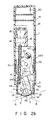
- Fig. 2(a) is a sectional view showing the internal structure of the copier shown in Fig. 1.
- Fig. 2(b) is a sectional view, taken along line II-II in Fig. 2(a).
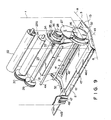
- Fig. 3 is a perspective view showing the main components arranged within the copier.
- Fig. 4 is a block diagram showing an electronic circuit.
- Fig. 5 is a flow chart explaining how to write image data into an image data memory when a specific data-reading width has been set.
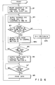
- Fig. 6 is a flow chart explaining how to print the image data read after a data-reading width has been set.
- FIG. 7 is a perspective view showing the outer appearance of a hand-held copier which is a second embodiment of the present invention.
- Fig. 8 a perspective view showing the outer appearance of a hand-held copier which is a third embodiment of the present invention.
- Fig. 9 is a perspective view showing the main components arranged within the copier of Fig. 8.
- Fig. 10 is a perspective view showing the outer appearance of the reading section of the copier of Fig. 8.
- Fig. 11 is a perspective view of a slider for closing the data-reading window of the copier shown in Fig. 8.
- Fig. 12 is a block diagram showing the electronic circuit of the copier shown in Fig. 8.
- Fig. 1 is a perspective view showing the first embodiment of the invention.
- numeral 1 designates the housing of the hand-held copier, which is 70 mm wide, 30 mm deep, and 160 mm high.
- the copier can read and print an image having a maximum width of 40 mm and can read an image having a maximum length of 200 mm. It can read and print an image in a resolution of 8 dots/mm at most.
- Head section HA which is designed to read and print an image, is attached to the distal end, or the lower end, of housing 1. Head section HA is not as wide or as deep as housing 1. Therefore, stepped portion D is formed between head section HA and housing 1.
- head section HA consists of two long, narrow inclined surfaces 1a and lb. These surfaces are joined at their lower sides, thus forming a ridge.
- Reading section 2 is mounted on surface la
- printing section 3 is mounted on surface lb.
- Power/read/print switch 4 is provided on one side of housing 1, and located at the lower end of this side.
- Operation keys 5a and 5b are provided on the front and rear surfaces of housing 1 , respectively.
- Operation keys 5a and 5b are shaped like plates. That portion of housing 1 on which these switches are provided, can be held between an operator's thumb and fingers, so that housing 1 of the hand-held copier can be moved back and forth.
- Power/read/print switch 4 serves to turn the copier on or off, and to set the copier in a reading mode or a printing mode. More precisely, when switch 4 is used in selecting either the reading mode or the printing mode, the power is supplied to the copier. Further, clear key 6, and density control dial 7 for controlling the print density are provided on the proximal (or upper) end of housing 1. Clear key 6 when pushed clears an image data memory (later described in detail) if the hand-held copier is set in the reading mode, and initializes the address of the image data memory when the copier is set in the printing mode. LED 8 is provided near reading section 2 and used as a power-supply pilot lamp. LEDs 9 and 10 are provided on the front surface of housing 1 , and located near the proximal end of housing 1. LED 9 is a memory pilot lamp, and LED 10 is a speed alarm lamp.
- key-input section 10a and a display section lOb are arranged on the front surface of housing 1.
- Key-input section lOa has numeric keys, a point key ".”, and a set key "SET". These keys function, thereby to set an effective data-reading width not exceeding 40 mm.
- the data-reading width set by operating key-input section 10a is displayed by display section lOb.
- power/read/print switch 4 In order to read image data of an original from the hand-held copier, power/read/print switch 4 is moved to a "read" position. The copier is thereby turned on, and LED 8 emits light. The operator holds the copier and sweeps it across the original, while depressing both operation keys 5a and 5b and keeping reading section 2 in contact with the original. When the copier is moved across the original at a speed higher than a predetermined value, LED 10 emits light, thereby informing the operator of this fact. In this case, when the desired data-reading width is less than the width of reading section 2 of head section H A , key-input section 10a has been operated, thus setting the effective data-reading width.
- power/read/print switch 4 is moved to a "print" position.
- the copier is then held and moved across a piece of recording paper A, in the direction of arrow X, while depressing both operation keys 5a and 5b and keeping printing section 3 in contact with paper A.
- the image data is printed on paper A.
- the printed image has a width equal to the effective data-reading width which has been set before the data-reading operation.
- Reading section 2 and printing section 3, both provided within housing 1, will now be described in detail with reference to Figs. 2(a) and 2(b) and Fig. 3.
- reading section 2 includes light source 11 made of an LED array and located close to inclined surface la. The light emitted from this light source is applied through window 12 of inclined surface la and illuminates original B.
- light guide 1 3 is arranged, and lens 14 and line image sensor 15 are located above light guide 13, and are spaced apart from each other for a predetermined distance.
- the line image sensor 15 is, for example, a 1024-bit CCD (charge coupled device).
- 320 bits are used to read an image having a maximum width of 40 mm, in a resolution of 8 dots/mm.
- Lens 14 and line image sensor 15 are held in specified positions by supporting member 16.
- This supporting member 16 is fastened to inner frame 17 provided within housing 1 by a predetermined distance therefrom.
- Space 18 accommodating electronic parts is provided within housing 1 , on one side of supporting member 16.
- Space 19 accommodating a battery is also provided within housing 1, and is connected to a circuit board (not shown) located in space 18.
- Clear key 6, density control dial 7, key-input section 10a, display section lOb, and the like, are connected to circuit board 20.
- thermal head 21 Within inner frame 17, there are provided thermal head 21, ink ribbon roll 22, roller 23 for feeding ribbon 22a at a constant speed, and ribbon take-up roller 24.
- Rubber rollers 25a and 25b, and gears 26, 27, 28, 29 and 30 are provided in the space between inner frame 17 and the inner surfaces of housing 1.
- Rubber rollers 2 5 a and 2 5 b are rotatably mounted on shaft 3 1 extending horizontally across inner frame 17 and protruding at both ends from inner frame 17. Parts of their peripheries outwardly protrude through slits 32 cut in the end portions of inclined surfaces la and lb.
- Gear 26, which has a smaller diameter than rubber rollers 25a, is coupled to gear 28 by intermediate gear 27.
- Gear 28 is coupled to the shaft of ribbon-feeding roller 23 by clutch 33.
- Encoder disk 34 is fastened to the input-end of clutch 33. Encoder disk 34 can rotate, independent of the one-way clutch 33 operation, when gear 28 rotates. As is shown in Fig. 3, encoder disk 34 has a number of radial slits 35 located at regular intervals in the circumferential direction of disk 34. LED 36 is located on one side of disk 34, and photosensor 37 is provided at the other end of disk 34. As is illustrated in Fig. 2(a), LED 36 is secured to the inner surface of housing 1, and photosensor 37 is fixed to the inner surface of inner frame 17.
- Hole 38 is cut in frame 17, coaxially positioned with respect to photosensor 3 7 . Hence, the light emitted from LED 36 can be applied to photosensor 37 through slits 35 of encoder disk 34 and through hole 38. Encoder disk 34, LED 36, and photosensor 37 constitute encoder 39.
- printing window 41 and ribbon-guiding window 42 are cut in inclined surface lb and extend parallel to one another. Ribbon-guiding window 42 is located nearer to inclined surface Ib than printing window 41 .
- Thermal head 2 1 has heating section 21a, which is inserted in printing window 41. Heating section 21a slightly protrudes from inclined surface lb. Slit 4 3 is cut in stepped portion D, close to that side of the housing on which operation key 5 b is provided. Thermal-transfer ink ribbon 22a fed out of roll 22 is led from housing 1 though slit 43, and then guided into housing 1 through ribbon-guiding window 42 after passing heating section 21a of thermal head 21.
- ink ribbon 22a is guided by shaft 3 1 , ink ribbon guide 4 4, and constant-speed ribbon-feeding roller 23, and is finally wound up around ribbon take-up roller 2 4 .
- the lower half of housing 1, on that side which operation switch 5b is mounted, can be opened when pivoted around hinge 45. When the lower half of this side is open, used ribbon roll 22 can be replaced, and the interior of housing 1 can be inspected.
- encoder 39 comprises encoder disk 34, LED 36, and photosensor 37.
- Encoder 39 outputs pulse signals representing the distance over which housing 1 has been moved. In other words, it outputs a distance signal.
- the distance signal output by encoder 39 is supplied to control section 51, timing signal-generating section 52, and speed-detecting section 53.
- Operation signals are supplied to control section 51 from power/read/print switch 4, opera-tion switches 5a and 5b, clear key 6, density control dial 7, and keys 54.
- a temperature signal is supplied to section 51 from temperature sensor 55 upon detection of the temperature of thermal head 21.
- a power-source voltage detector (not shown) is provided in control section 51.
- Control section 51 controls power-supply pilot LED 8 and memory pilot LED 9 of LED section 50, and also controls the other components of the circuit.
- control section 5 1 gives operation commands S1 or S2 to timing signal-generating section 5 2. More specifically, control section 51 supplies command S1 to section 52 when the reading mode is selected, and command S2 to section 52 when the printing mode is selected.
- timing signal-generating section 52 When operation command S1 is supplied from control section 51 to timing signal-generating section 52, timing signal-generating section 52 generates CCD-exposure timing signals at regular intervals. Further, section 52 generates various timing signals such as a predetermined number of read-timing signals a, serial-to-parallel conversion signals b, clock pulses c, and encoder pulses h, in synchronism with the output signal of encoder 39 which represents the distance which the hand-held copier has been moved. Section 52 generates print-timing signals upon receiving opera- tion command S2 from control section 51. The CCD-exposure timing signals output from timing signal-generating section 51 are supplied to line image sensor 15. Read-timing signals a are supplied to A/D converting section 57.
- Serial-to-parallel conversion signals b are supplied to serial-to-parallel conversion section 58.
- Clock pulses c are supplied to address counter 62 via AND gate AND3, OR gate OR1 and AND gate AND5 .
- Encoder pulses h are supplied through OR gate OR2 to reset terminal R of counter 61 (later described).
- Line image sensor 1 5 receives the light reflected from original B in synchronism with the CC D -exposure timing signals, and output analog signals. The output signals of the image sensor are output to A /D converting section 57 via amplifier 56.
- A/D converting section 57 converts these signals into binary signals, i.e., black and white signals, in synchronism with read-timing signals a.
- serial-to-parallel conversion section 58 converts the input signals to, for example, an 8-bit parallel signal.
- This parallel signal is output to image data memory 60 via data selector 59.
- Read signal R is supplied to image data memory 60 from control section 51 via AND gate ANDl
- write signal W is supplied from section 51 via AND gate AND2.
- Both AND gates AND1 and AND2 are turned on by a "1" (high) level signal output from comparator circuit 6 4 (later described).
- Data selector 59 is connected to control section 5 1 by a data line, and selects either control section 51 or image data memory 60 in accordance with selection signal d supplied from control section 51.
- a desired write address of image data memory 60 (a line address and a digit address) is designated by address counter 62.
- Clock pulses c are supplied to address counter 62 from timing signal-generating section 51 via AND gate AND3, OR gate OR1 and AND gate AND5.
- AND gate AND3 is turned on by read command S1 supplied by control section 51.
- AND gate AND5 is turned on by a "1" (high) level signal output from comparator circuit 64.
- Any desired read address of image data memory 60 is given from address counter 62 under control of control section 51.
- address counter 62 counts up the read addresses in response to address signals e supplied from control section 51 via AND gate AND4, OR gate ORl, and AND gate AND5.
- AND gate AND4 is turned on by print command S2 supplied from control section 51.
- Comparator circuit 64 receives and compares designated reading-width data and designated write- or read-address data.
- the designated reading-width data corresponds to the address value latched in latch circuit 63
- the designated write- or read-address data corresponds to the count value of counter 61.
- comparator circuit 64 When the designated reading-width data is greater than the designated write- or read-address data, comparator circuit 64 outputs a "1" signal to AND gates ANDl, AND2, and AND5.
- comparator circuit 64 outputs a "0" signal to AND gates ANDl, AND2, and AND5.
- control section 51 When the hand-held copier is set in the printing mode after the image has been read from the original B, control section 51 outputs operation command S2 to timing signal-generating section 52, as has been described above. Section 51 then sequentially reads the data stored in image data memory 60 via data selector 59, in response to the output distance signal by encoder 39. After reading the image data from image data memory 60, control section 51 calculates the time for supplying power to thermal head 2 1 , based on the number of black characters represented by the print data, the temperature of head 21 detected by temperature sensor 55, the data output by the power-source voltage detector, and the density selected by turning density control dial 7. The data representing the power-supplying time is output as print data to thermal head-driving circuit 65. In accordance with this print data, thermal head-driving circuit 65 drives thermal head 21 in synchronism with the timing signals supplied from timing signal-generating section 52.
- timing signal-generating section 52 generates CCD-exposure timing signals in response to operation command S1 supplied by control section 51, and supplies these CCD-exposure timing signals to line image sensor 15. Further, section 52 generates, also in response to operation command S1, read-timing signals a and serial-to-parallel conversion signals b, and supplies signals a to A/D converting section 57, and signals b to serial-to-parallel conversion section 58. Still further, timing signal-generating section 5 2 generates clock pulses c in synchronism with serial-to-parallel conversion signals b. These pulses c are supplied to counter 61 and address counter 62.
- Line image sensor 15 produces image signals from the light reflected off original B, in synchronism with CCD-exposure timing signals output from timing signal-generating section 52.
- the image signals are amplified by amplifier 56 and then supplied to A / D converting section 57.
- A/D converting section 57 converts the image signals output from amplifier 56, into a serial-digital signal, in synchronism with read-timing signals a supplied from timing signal-generating section 52.
- the digital signal is input to serial-to-parallel conversion section 58.
- Serial-to-parallel conversion section 58 converts the serial-digital signal into, for example, 8-bit parallel image data, in synchronism with serial-to-parallel conversion signals b supplied by timing signal-generating section 52.
- the 8-bit image data is output to data selector 59.
- Data selector 59 selectively delivers the output of serial-to-parallel conversion section 58, in response to selection signal d supplied by control section 51 when the copier is set in the reading mode. Therefore, the image data output from serial-to-parallel conversion section 58 is supplied to image data memory 60 via data selector 59.
- the write addresses of image data memory 60 are designated by address counter 62. In this case, no reading-width has yet been specified. Hence, comparator circuit 64 outputs a "1" signal at all times.
- the count value of address counter 62 which defines the digit address, is incremented by "+1" every time clock pulse c is input to address counter 62 from timing signal-generating section 52.
- Timing signal-generating section 52 stops producing timing signals after the image data for one line has been written into image data memory 60. It refrains from producing timing signals until it receives the next pulse signal from encoder 39, which represents the distance the copier has been moved. The sequence of the operations described above is repeated, whereby the image data read from original B is written line by line into image data memory 60.
- step Rl encoder pulses are generated from encoder 39, as housing 1 is moved.
- step R2 counter 61 is reset by the first encoder pulse h supplied by timing signal-generating section 5 2.
- step R3 the image signals output from line image sensor 15 via A/D converting section 57 are converted into 8-bit parallel signals by serial-to-parallel conversion section 58.
- clock pulses c are supplied from timing signal-generating section 52 to counter 61 and address counter 62.
- step R5 comparator circuit 64 compares the designated reading-width data, which has been converted to the address value and latched in latch circuit 63, with the address value counted by counter 61 and representing the distance, in the main scanning direction, the original B has actually been scanned, in other words, it is determined in step R5 whether or not the count value of counter 61 is less than the designated reading width. If Yes, that is, if the distance is shorter than the designated reading width, comparator circuit 64 outputs a "1" signal in step R6. As a result, the image signals, i.e., the parallel signals output from serial-to-parallel conversion section 58, are written via data selector 59 at the write address of image data memory 60, which has been designated by address counter 62.
- step R 7 it is determined whether or not one-line image data has been read from the original. If it is determined, from the output of encoder 39, that the one-line image data has not been read, steps R3 through R 6 are repeated, the image signals further output from serial-to-parallel conversion section 58 are sequentially written into write addresses of image data memory 70, which are sequentially designated by address counter 62.
- comparator circuit 64 When line image sensor 15 has scanned the original over the designated reading width of 35 mm in the main scanning direction, comparator circuit 64 outputs a "0" signal. In other words, a result "No" is obtained in step R5. In this case, AND gate AND 2 is turned off, thereby stopping the writing of data into image data memory 60.
- control section 51 supplies selection signal d to data selector 5 9, whereby data selector 59 is switched to the side of control section 51.
- the user sweeps housing 1 across a sheet of paper A in the direction of arrow X (Fig. 1), while keeping printing section 3 of head section H A in contact with paper A and depressing both operation keys 5a and 5b.
- the output signal of encoder 39 i.e., the output pulses of photosensor 3 7 , which represents the distance the copier has been moved, are supplied to control section 51, timing signal-generating section 52, and speed-detecting section 53.
- Timing signal-generating section 52 supplies a one-line printing command to control section 51 in response to the output signal of encoder 39. It also supplies print-timing signals to thermal head-driving circuit 65 in response to the output signal of encoder 39.
- control section 51 designates one after another, the line addresses and digit addresses of image data memory 60. Hence, the image data stored in image data memory 60 is read out through data selector 59 and is input line by line, to thermal head-driving circuit 65.
- control section 51 calculates and sets the time for supplying power to thermal head 21, based on the number of black characters represented by the print data, the temperature of thermal head 21 detected by temperature sensor 55, the output signal of the power-source voltage detector, and the density selected by rotating density control dial 7. Then, control section 51 supplies thermal head-driving circuit 65 with the image data read out from image data memory 60. Thermal head-driving circuit 65 drives thermal head 21 in accord-ance with the control data supplied by control section 51 and the timing signals output from timing signal-generating section 52. Thermal head 21 prints the image data on paper A using ink ribbon 22a.
- the hand-held copier is operated as shown in the flow chart of Fig. 6.
- control section 51 When the printing mode is set, control section 51 outputs print command S2 in step W l. At the same time, a one-line reading start signal is output from control section 51 to counter 61 through OR gate OR2, thereby resetting counter 61.
- address signal e (a pulse signal), which designates a read address, is supplied through AND gate AND4 to counter 61 and address counter 62. Then, counter 61 begins counting the addresses corresponding to the dot elements of thermal head 21 arranged in a dot direction. Also, address counter 62 begins counting read addresses of image data memory 60.
- step W3 comparator circuit 64 compares the address value counted by counter 61 and representing the position of any dot element, with the designated reading-width data was latched at the beginning of the data-reading operation. When the address value for the dot element is less than the designated reading-width data, comparator circuit 64 outputs a "1" signal. If this is the case, in the next step, W4 a, the image data is read from the read address of image data memory 60, which has been designated by address counter 62. This image data is input to the print data register provided within control section 5 1 via data selector 59. In step W5, it is determined whether the one-line image data has been read to control section 51 or not. If No, steps W2 through W4a are repeated, whereby print data is read out item by item, from image data memory 60 to control section 51.
- step W3 If Y es in step W3 , that is, if the address value counted by counter 61 reaches the value of designated reading-width data, it is determined that one-line print data representing a line of image which is 35.5 mm long is fetched in control section 51. Then, comparator circuit 64 outputs a "0" signal. As a result, data-reading from image data memory 60 is prohibited, and address counter 62 also stops counting read addresses. Then, steps W2, W3, W4b and W5 are repeated, whereby "0" (blank) data is input to the print data register of control section 51, in the memory region for 5 mm of this register, along with image data for 35.5 mm (i.e., the designated reading width).
- step W6 the image data is transferred from the print data register to thermal head-driving circuit 65.
- This image data includes the image data for the designated reading width, which has been read from image data memory 60, and the blank data, and corresponds to one line of dot elements of thermal head 21.
- step W7 it is determined whether or not encoder 39 has output an encoder pulse, showing that housing 1 has been further moved. If Yes, thermal head-driving circuit 6 5 supplies the one-line print data to thermal head 21, in accordance with print-timing signals supplied from timing signal-generating section 52.
- step W8 the image data for one line of dots is printed.
- the first line of the image data which has been read over the designated reading-width and then written into image data memory 60, as shown in the flow chart of Fig. 5, is printed on paper A for the distance equivalent to the designated reading width.
- steps W1 to W8 are repeated, all image data read from the original B and written into image data memory 60 is read out from memory 60, line by line, and the lines of the image, which have the length equal to the designated reading width, are printed on paper A, one after another.
- latch circuit 63 stores the value input by operating key-input section 10a. Instead, it can store a value obtained by multiplying the key-input value by a predetermined constant. Any data that can be compared with the count value of counter 61 can be stored in latch circuit 63.
- a reading width is designated by depressing the numeral keys of key-input section 10a.
- slide switch 10c can be used to designate the reading width, as is shown in F ig. 7 which illustrates a second embodiment of the present invention.
- the hand-held copier of the second embodiment has slide switch 10c on the front of housing 1.
- Slide switch 1 0c has projection 10d which can be pushed to the left or the right, for a distance up to 40 mm.
- the position of this projection 10d defines a reading width.
- the data representing this reading width is input to control section 51 shown in Fig. 4.
- the copier of the second embodiment can read and print image data in the same way as the first embodiment, as is shown in the flow charts of Figs. 5 and 6.
- the reading width is designated by electronic means.
- the reading width is set by mechanical means. More precisely, a sliding member is moved, thereby to close and open, to various degrees, the image data-reading window made in housing 1, in order to designate a desired reading width.
- a pair of sliding members 4 6a and 46b for adjusting the reading width are slidably fitted in data-reading window 12.
- the backs of sliding members 46a and 46b, which oppose light source 11, are coated white so that their reflectivity is about 80%.
- these members are made with a plate of transparent material such as acrylic resin and surfaces thereof are coated white, thereby eliminating variation in forcal distance viewed from light source 11.
- Pointers 47 is integrally formed with each of sliding members 46a and 46b at the ends thereof, so that pointers 47 are located on scale 48 provided on the lower edge of the front of housing 1. When sliding members 46a and 46b are moved, pointers 47 are also moved for the same distance. Therefore, the positions of pointers 47 with respect to scale 48 indicate the reading width selected by moving sliding members 46a and 46b.
- encoder 39 comprises encoder disk 34, LED 36, and photosensor 37, and outputs a pulse signal representing the distance for which housing 1 has been moved.
- the output signal of encoder 39 is supplied to control section 51, timing signal-generating section 52, and speed-detecting section 53.
- Speed-detecting section 53 detects, from the output signal of encoder 39, whether or not the speed of housing 1 is higher than a preset value. When section 53 detects that housing 1 is being moved at a speed higher than the preset value, it causes LED 10 of LED section 50, i.e., a speed alarm lamp, to emit light.
- control section 51 Various operations signals are supplied to control section 51 from power/read/print switch 4, operation keys 5a and 5b, clear key 6, density control dial 7, and switches 54. Further, a temperature signal is supplied to control section 51 from temperature sensor 55 which has detected the temperature of thermal head 21. Control section 51 is provided with a power-source voltage detector (not shown). In accordance with the input signals, control section 51 controls LED 8 (power-supply monitor), LED 9 (memory pilot lamp), both included in LED section 50, and other components. It also gives an operation command to timing signal-generating section 5 2 when power/read/print switch 4 is operated, thus setting the copier in a reading mode or a printing mode.
- LED 8 power-supply monitor
- LED 9 memory pilot lamp
- Timing signal-generating section 52 generates CCD-exposure timing signals at regular intervals, in response to the command supplied from control section 51. Further, section 52 generates various timing signals such as a predetermined number of read-timing signals a, serial-to-parallel conversion signals b, and clock pulses c, in synchronism with the output signal of encoder 39.
- the CCD-exposure timing signals output from timing signal-generating section 52 are supplied to line image sensor 1 5 .
- Read-timing signals a are supplied to A/D converting section 57.
- Serial-to-parallel conversion signals b are supplied to serial-to-parallel conversion section 58.
- Clock pulses c are supplied to address counter 61.
- Line image sensor 15 receives the light reflected from original B in synchronism with the CCD-exposure timing signals, and produces output signals.
- the output signals of the image sensor are output to A/D converting section 57 via amplifier 56.
- A/D converting section 57 converts these signals into binary signals, i.e., black and white signals, in synchronism with read-timing signals a.
- the binary signals are supplied to serial-to-parallel conversion section 58.
- Serial-to-parallel conversion section 58 converts the input signals into, for example, an 8-bit parallel signal. This parallel signal is output to image data memory 60 through data selector 59.
- Data selector 59 is connected to control section 51 by a data line, and selects either control section 51 or serial-to-parallel conversion section 58 in accordance with selection signal d supplied from control section 51.
- Any desired write address of image data memory 60 (a line-address and a digit-address) is defined by the count value of address counter 66 and designated by address selector 67.
- any desired read address of image data memory 60 is given from control section 51 through address selector 67.
- Address selector 6 7 selects, in accordance with selection signal e output from section 51, address counter 66 when the copier is set in the reading mode, and selects control section 51 when the copier is set in the printing mode, thereby to designate the desired address of image data memory 60.
- control section 51 When the hand-held copier is set in the printing mode after the image has been read from the original, control section 51 starts sequentially reading the data stored in image data memory 60 through data selector 59, in response to the output signal of encoder 39. After reading the image data from image data memory 60, control section 51 calculates the time for supplying power to thermal head 21, on the basis of the temperature of head 21 detected by temperature sensor 55, the data output by the power-source voltage detector, and the density selected by turning density control dial 7. The data representative the power-supplying time is output as print data to thermal head-driving circuit 65. In accordance with this print data supplied from section 51, thermal head-driving circuit 65 drives thermal head 21 in synchronism with the timing signals supplied from timing signal-generating section 52.
- the user sweeps housing 1 of the copier across a desired part of original B forwardly in the direction of operation key 5a (Fig. 1) side, while keeping reading section 2 of head section HA in contact with original B and depressing both operation keys 5a and 5b.
- the light emitted from light source 11 is applied onto original B through reading window 12 cut in inclined surface l a.
- the light is reflected from original B and guided by light guide 13.
- the light is finally applied via lens 14 to line image sensor 15.
- the opening length of window 12, i.e., the reading width is the distance between sliding members 46a and 4 6b which have been moved to desired positions.
- Timing signal-generating section 52 generates CCD-exposure timing signals at regular intervals and supplies these signals to line image sensor 15. Further, section 52 generates read-timing signals a and serial-to-parallel conversion signals b in response to the output signal of encoder 39, and supplies signals a to A /D converting section 57 and signals b to serial-to-parallel conversion section 58. Still further, timing signal-generating section 5 2 generates clock pulses c in synchronism with serial-to-parallel conversion signals b, and supplies these pulses c to address counter 66 and address selector 67.
- Line image sensor 15 produces image signals from the light reflected from original B, in synchronism with CCD-exposure timing signals supplied from timing signal-generating section 52.
- the image signals are amplified by amplifier 56 and then supplied to A/D converting section 57.
- A/D converting section 57 converts the image signals output from amplifier 56, into a serial, digital signal, in synchronism with read-timing signals a supplied from timing signal-generating section 52.
- the digital signal is input to serial-to-parallel conversion section 58.
- Serial-to-parallel conversion section 5 8 converts the serial digital signal into, for example, 8-bit parallel image data, in synchronism with serial-to-parallel conversion signals b supplied from timing signal-generating section 52.
- the 8-bit image data is output to data selector 59.
- Data selector 59 selects the output of the serial-to-parallel conversion section 58 when the copier is set in the reading mode, in response to selection signal d supplied from control section 51. Therefore, the image data output from serial-to-parallel conversion section 58 is supplied via data selector 59 to image data memory 60.
- the addresses of image data memory 60 are designated by address selector 6 7 . In this case, address selector 6 7 selects the output of address counter 66 in accordance with selection signal e supplied from control section 51. Therefore, the addresses of memory 60 are designated by the count value of address counter 66.
- the count value of address counter 66 is incremented by "+1" every time a clock pulse c is input to counter 66 from timing signal-generating section 52.
- the addresses of image data memory 60 are sequentially designated.
- Timing signal-generating section 52 stops generating timing signals when the image data for one line has been written into image data memory 60. It remains to produce timing signals until it receives the next pulse signal from encoder 39, which represents the distance the copier has been moved. The sequence of the above operations is repeated, whereby the image data read from original B through reading window 12 by scanning original over the preset reading width, and written into image data memory 60.
- control section 51 supplies selection signals d and e, whereby data selector 59 and address selector 67 select control section 51.
- the user sweeps housing 1 across a sheet of paper A in the direction of arrow X (Fig. 1), while keeping printing section 3 of head section HA in contact with paper A and depressing both operation keys 5a and 5b.
- housing 1 is moved in this manner, rubber rollers 25a and 25b rotate, thus rotating gears 26, 27, and 28.
- Encoder disk 34 is therefore rotated.
- Photosensor 37 outputs pulses, as in the case of reading the image data, which form a signal which represents the distance the copier has been moved across paper A.
- the output signal of encoder 39 i.e., the output pulses of photosensor 37, which represents the distance the copier has been moved, is supplied to control section 51, timing signal-generating section 52, and speed-detecting section 53.
- Timing signal-generating section 52 supplies print-timing signals to thermal head-driving circuit 65 in response to the output signal of encoder 39.
- Control section 51 designates, in response to the output signal of encoder 39, the line addresses and digit addresses of image data memory 60, one after another, thereby reading the image data from memory 60 through data selector 59.
- control section 51 sets the time for supplying power to thermal head 21, based on the temperature of head 21 detected by temperature sensor 55, the output signal of the power-source voltage detector, and the density selected by turning density control dial 7. Then, control section 51 supplies thermal head-driving circuit 65 with the image data read out of image data memory 60. Thermal head-driving circuit 65 drives thermal head 21 in accordance with the control data supplied from control section 51 and the timing signals output from timing signal-generating section 52. Thermal head 21, therefore, prints the image data on paper A by using ink ribbon 22a. As housing 1 of the hand-held copier is moved across paper A, the unused portion of ink ribbon 22a is fed from roll 22, whereas the used portion of ribbon 22a is taken up around ribbon take-up roller 24. In this manner, the image data stored in image data memory 60 is printed on paper A as housing 1 is swept across paper A.
Abstract
Applications Claiming Priority (4)
| Application Number | Priority Date | Filing Date | Title |
|---|---|---|---|
| JP134893/86 | 1986-06-12 | ||
| JP61134893A JPS62292063A (ja) | 1986-06-12 | 1986-06-12 | 画像デ−タ読取装置 |
| JP61309421A JP2531160B2 (ja) | 1986-12-24 | 1986-12-24 | 画像デ−タ読取り装置 |
| JP309421/86 | 1986-12-24 |
Publications (3)
| Publication Number | Publication Date |
|---|---|
| EP0278004A1 true EP0278004A1 (fr) | 1988-08-17 |
| EP0278004A4 EP0278004A4 (fr) | 1990-01-08 |
| EP0278004B1 EP0278004B1 (fr) | 1994-02-09 |
Family
ID=26468881
Family Applications (1)
| Application Number | Title | Priority Date | Filing Date |
|---|---|---|---|
| EP87903913A Expired - Lifetime EP0278004B1 (fr) | 1986-06-12 | 1987-06-12 | Copieur de petite dimension |
Country Status (5)
| Country | Link |
|---|---|
| US (1) | US4899228A (fr) |
| EP (1) | EP0278004B1 (fr) |
| DE (1) | DE3789056T2 (fr) |
| HK (1) | HK68696A (fr) |
| WO (1) | WO1987007804A1 (fr) |
Cited By (6)
| Publication number | Priority date | Publication date | Assignee | Title |
|---|---|---|---|---|
| EP0332114A2 (fr) * | 1988-03-07 | 1989-09-13 | Casio Computer Company Limited | Appareil de balayage pour la lecture de données d'image |
| EP0527573A2 (fr) * | 1991-08-12 | 1993-02-17 | Brother Kogyo Kabushiki Kaisha | Copieur portatif |
| EP0592132A1 (fr) * | 1992-10-05 | 1994-04-13 | Hewlett-Packard Company | Procédé et dispositif de balayage et d'impression |
| EP0665115A2 (fr) * | 1994-01-28 | 1995-08-02 | Casio Computer Co., Ltd. | Appareil capable de lire et d'imprimer des images |
| WO1998000965A1 (fr) * | 1996-06-27 | 1998-01-08 | Mm-Lesestift Manager Memory Gmbh | Lecteur pour la detection optique et la memorisation de signes, de graphiques et d'images photographiques alphanumeriques projetes, a marquage visuel |
| GB2376368A (en) * | 2001-04-20 | 2002-12-11 | Hewlett Packard Co | Image capture device with task assigner |
Families Citing this family (39)
| Publication number | Priority date | Publication date | Assignee | Title |
|---|---|---|---|---|
| JPH01501112A (ja) * | 1986-10-06 | 1989-04-13 | ドゥ フェイ,ステファン,グリゴール | 表示されている図形記号を記録し、保存し場合によりこれを処理し又再生するための方法及び携帯用装置 |
| US5079639A (en) * | 1989-02-10 | 1992-01-07 | Casio Computer Co., Ltd. | Hand-held, manually sweepable image data processing apparatus |
| JPH039657A (ja) * | 1989-06-07 | 1991-01-17 | Hitachi Ltd | 画像読取り処理装置 |
| GB9014487D0 (en) * | 1990-06-29 | 1990-08-22 | Alcatel Business Systems | Hand held portable device |
| WO1992016376A1 (fr) * | 1991-03-12 | 1992-10-01 | Ideograph Associates | Machine a ecrire pour ideogrammes, et methode |
| US5392447A (en) * | 1992-01-10 | 1995-02-21 | Eastman Kodak Compay | Image-based electronic pocket organizer with integral scanning unit |
| AU7335294A (en) * | 1993-07-16 | 1995-02-13 | Fullon Image, Inc. | Palm scanner having folded optics and a guide rail |
| CN1086643C (zh) * | 1994-02-22 | 2002-06-26 | 表意符号合伙人公司 | 表意文字打字机及打字方法 |
| US6068420A (en) * | 1995-05-30 | 2000-05-30 | Intermec Ip Corporation | Printer with an integrally formed spring for biasing the printhead |
| US5751330A (en) * | 1995-05-30 | 1998-05-12 | Intermec Corporation | Printer for printing on media roll |
| US5593236A (en) * | 1995-11-06 | 1997-01-14 | Bobry; Howard H. | Hand-held sweep electronic printer with compensation for non-linear movement |
| US5595445A (en) * | 1995-12-27 | 1997-01-21 | Bobry; Howard H. | Hand-held optical scanner |
| US5777321A (en) * | 1996-01-29 | 1998-07-07 | Hewlett-Packard Company | Scanning device with non-contact optical components |
| US5723859A (en) * | 1996-01-29 | 1998-03-03 | Hewlett-Packard Company | Line contact hand-held scanning device and method having a light path substantially perpendicular to the orientation of the object at a line portion |
| US5825995A (en) * | 1996-03-11 | 1998-10-20 | Intermec Technologies, Inc. | Printer with motion detection |
| JPH1024627A (ja) * | 1996-03-28 | 1998-01-27 | Intermec Corp | プリンタおよび印刷方法 |
| US6015211A (en) * | 1996-06-21 | 2000-01-18 | Brother Kogyo Kabushiki Kaisha | Portable printing device with shutter for covering print head |
| US5988900A (en) * | 1996-11-01 | 1999-11-23 | Bobry; Howard H. | Hand-held sweep electronic printer with compensation for non-linear movement |
| JPH10134163A (ja) * | 1996-11-05 | 1998-05-22 | Pfu Ltd | スキャナ付き装置 |
| US7379218B1 (en) * | 1996-11-05 | 2008-05-27 | Fujitsu Limited | Apparatus equipped with removable scanner unit |
| US6064496A (en) * | 1997-06-18 | 2000-05-16 | Hewlett-Packard Company | Scanning device with floating window member |
| US5995243A (en) * | 1997-06-18 | 1999-11-30 | Hewlett-Packard Company | Illumination system with white level calibration for hand-held scanner |
| US6639203B1 (en) | 1997-07-02 | 2003-10-28 | Hewlett-Packard Development Company, L.P. | Catadioptric lens system for a scanning device |
| JPH1158844A (ja) * | 1997-08-08 | 1999-03-02 | Hewlett Packard Co <Hp> | ハンディ・プリンタ・システム |
| JPH1166268A (ja) * | 1997-08-13 | 1999-03-09 | Fujitsu Ltd | 画像読取装置 |
| US6118553A (en) * | 1998-01-28 | 2000-09-12 | Hewlett-Packard Company | Compact motor drive and active speed governor with optical encoder for scanner mechanisms |
| US6097507A (en) * | 1998-04-07 | 2000-08-01 | Hewlett-Packard Company | Portable scanner with pivoting image head and rotating mirror |
| US6292274B1 (en) * | 1998-12-11 | 2001-09-18 | Hewlett-Packard Company | Portable scanner with tilting body design |
| AU746703B2 (en) * | 1998-12-24 | 2002-05-02 | Canon Kabushiki Kaisha | Printer apparatus |
| US6268598B1 (en) * | 1999-10-14 | 2001-07-31 | Hewlett Packard Company | Hand-held scanner apparatus having visual scan-region position feedback system |
| SE516915C2 (sv) * | 2000-07-06 | 2002-03-19 | Print Dreams Europe Ab | Elektronisk stämpel |
| US6952880B2 (en) * | 2001-08-27 | 2005-10-11 | Hewlett-Packard Development Company, L.P. | Measurement and marking device |
| AUPS049402A0 (en) * | 2002-02-13 | 2002-03-07 | Silverbrook Research Pty. Ltd. | Methods and apparatus (ap55) |
| AUPS048602A0 (en) | 2002-02-13 | 2002-03-07 | Silverbrook Research Pty. Ltd. | Methods and systems (ap46) |
| US20040100663A1 (en) * | 2002-11-26 | 2004-05-27 | Pisczak Spencer N. | Hand-held scanning and marking apparatus |
| CN1910050A (zh) * | 2004-01-15 | 2007-02-07 | 皇家飞利浦电子股份有限公司 | 具有扫描器和分配器的电子画笔 |
| JP4971241B2 (ja) * | 2008-05-09 | 2012-07-11 | 株式会社リコー | 画像表示装置 |
| US20120050825A1 (en) * | 2010-08-24 | 2012-03-01 | Mr. Raja Singh Tuli | Keichain scanner |
| TWI733053B (zh) * | 2018-09-07 | 2021-07-11 | 虹光精密工業股份有限公司 | 事務機與事務機的操控組件之控制方法 |
Citations (6)
| Publication number | Priority date | Publication date | Assignee | Title |
|---|---|---|---|---|
| JPS5776973A (en) * | 1980-10-29 | 1982-05-14 | Matsushita Electric Ind Co Ltd | Tranfer machine |
| JPS57131166A (en) * | 1981-02-06 | 1982-08-13 | Ricoh Co Ltd | Partial read and record control device |
| DE3422120A1 (de) * | 1983-06-15 | 1984-12-20 | Canon K.K., Tokio/Tokyo | Bildlesegeraet |
| US4523235A (en) * | 1982-01-11 | 1985-06-11 | Jan Rajchman | Electronic microcopier apparatus |
| JPS60244150A (ja) * | 1984-05-18 | 1985-12-04 | Nippon Kogaku Kk <Nikon> | 画像入力装置の走査巾設定装置 |
| EP0231697A1 (fr) * | 1985-12-27 | 1987-08-12 | Bertrand Alain Dreyfus | Appareil portatif de photocopie de fragments de documents |
Family Cites Families (7)
| Publication number | Priority date | Publication date | Assignee | Title |
|---|---|---|---|---|
| US3541248A (en) * | 1967-09-29 | 1970-11-17 | Xerox Corp | Document abstractor with hand-held optical scanner with constant resolution scanning |
| US3767020A (en) * | 1971-07-02 | 1973-10-23 | Ibm | Manually positionable automatic printer |
| JPS55115773A (en) * | 1979-02-27 | 1980-09-05 | Ricoh Co Ltd | Copy machine of manual subscanning type |
| JPS57119553A (en) * | 1981-01-17 | 1982-07-26 | Ricoh Co Ltd | Read width switching and display device of manual reader |
| JPS59230362A (ja) * | 1983-06-13 | 1984-12-24 | Nippon Kogaku Kk <Nikon> | コピ−装置 |
| JPS60126632A (ja) * | 1983-12-14 | 1985-07-06 | Matsushita Electric Ind Co Ltd | 複写機 |
| US4717965A (en) * | 1985-01-17 | 1988-01-05 | Ricoh Company, Ltd. | Portable image forming device |
-
1987
- 1987-06-12 EP EP87903913A patent/EP0278004B1/fr not_active Expired - Lifetime
- 1987-06-12 US US07/171,873 patent/US4899228A/en not_active Expired - Lifetime
- 1987-06-12 DE DE3789056T patent/DE3789056T2/de not_active Expired - Lifetime
- 1987-06-12 WO PCT/JP1987/000380 patent/WO1987007804A1/fr active IP Right Grant
-
1996
- 1996-04-18 HK HK68696A patent/HK68696A/xx not_active IP Right Cessation
Patent Citations (6)
| Publication number | Priority date | Publication date | Assignee | Title |
|---|---|---|---|---|
| JPS5776973A (en) * | 1980-10-29 | 1982-05-14 | Matsushita Electric Ind Co Ltd | Tranfer machine |
| JPS57131166A (en) * | 1981-02-06 | 1982-08-13 | Ricoh Co Ltd | Partial read and record control device |
| US4523235A (en) * | 1982-01-11 | 1985-06-11 | Jan Rajchman | Electronic microcopier apparatus |
| DE3422120A1 (de) * | 1983-06-15 | 1984-12-20 | Canon K.K., Tokio/Tokyo | Bildlesegeraet |
| JPS60244150A (ja) * | 1984-05-18 | 1985-12-04 | Nippon Kogaku Kk <Nikon> | 画像入力装置の走査巾設定装置 |
| EP0231697A1 (fr) * | 1985-12-27 | 1987-08-12 | Bertrand Alain Dreyfus | Appareil portatif de photocopie de fragments de documents |
Non-Patent Citations (4)
| Title |
|---|
| PATENT ABSTRACTS OF JAPAN, vol. 10, no. 104 (E-397)[2161], 19th April 1986; & JP-A-60 244 150 (NIHON KOUGAKU KOGYO K.K.) 04-12-1985 * |
| PATENT ABSTRACTS OF JAPAN, vol. 6, no. 155 (E-125)[1033], 17th August 1982; & JP-A-57 076 973 (MATSUSHITA K.K.) 14-05-1982 * |
| PATENT ABSTRACTS OF JAPAN, vol. 6, no. 230 (E-142)[1108], 16th November 1982; & JP-A-57 131 166 (RICOH K.K.) 13-08-1982 * |
| See also references of WO8707804A1 * |
Cited By (14)
| Publication number | Priority date | Publication date | Assignee | Title |
|---|---|---|---|---|
| EP0332114A3 (en) * | 1988-03-07 | 1990-05-16 | Casio Computer Company Limited | Sweeping apparatus for reading image data |
| US4969054A (en) * | 1988-03-07 | 1990-11-06 | Casio Computer Co., Ltd. | Hand-held manually sweeping apparatus for reading image data |
| EP0332114A2 (fr) * | 1988-03-07 | 1989-09-13 | Casio Computer Company Limited | Appareil de balayage pour la lecture de données d'image |
| EP0527573A2 (fr) * | 1991-08-12 | 1993-02-17 | Brother Kogyo Kabushiki Kaisha | Copieur portatif |
| EP0527573A3 (en) * | 1991-08-12 | 1993-04-07 | Brother Kogyo Kabushiki Kaisha | Portable copying device |
| US5446559A (en) * | 1992-10-05 | 1995-08-29 | Hewlett-Packard Company | Method and apparatus for scanning and printing |
| EP0592132A1 (fr) * | 1992-10-05 | 1994-04-13 | Hewlett-Packard Company | Procédé et dispositif de balayage et d'impression |
| EP0665115A2 (fr) * | 1994-01-28 | 1995-08-02 | Casio Computer Co., Ltd. | Appareil capable de lire et d'imprimer des images |
| EP0665115A3 (fr) * | 1994-01-28 | 1998-10-28 | Casio Computer Co., Ltd. | Appareil capable de lire et d'imprimer des images |
| WO1998000965A1 (fr) * | 1996-06-27 | 1998-01-08 | Mm-Lesestift Manager Memory Gmbh | Lecteur pour la detection optique et la memorisation de signes, de graphiques et d'images photographiques alphanumeriques projetes, a marquage visuel |
| AU720325B2 (en) * | 1996-06-27 | 2000-05-25 | Mm-Lesestift Manager Memory Gmbh | Data acquisition device for optically acquiring and storing visually marked and projected alphanumerical characters, graphics and photographic picture and/or three-dimensional topographies |
| GB2376368A (en) * | 2001-04-20 | 2002-12-11 | Hewlett Packard Co | Image capture device with task assigner |
| GB2376368B (en) * | 2001-04-20 | 2005-11-23 | Hewlett Packard Co | Portable photo scanner with task assigner |
| US7595914B2 (en) | 2001-04-20 | 2009-09-29 | Hewlett Packard Development Company, L.P. | Portable photo scanner with task assigner |
Also Published As
| Publication number | Publication date |
|---|---|
| DE3789056T2 (de) | 1994-05-19 |
| HK68696A (en) | 1996-04-26 |
| DE3789056D1 (de) | 1994-03-24 |
| EP0278004A4 (fr) | 1990-01-08 |
| US4899228A (en) | 1990-02-06 |
| WO1987007804A1 (fr) | 1987-12-17 |
| EP0278004B1 (fr) | 1994-02-09 |
Similar Documents
| Publication | Publication Date | Title |
|---|---|---|
| EP0278004B1 (fr) | Copieur de petite dimension | |
| US4947262A (en) | Hand-held manually sweeping printing apparatus | |
| EP0270686B1 (fr) | Processeur de donnees d'image a balayage manuel | |
| US4684998A (en) | Image reader suitable for manual scanning | |
| US4819083A (en) | Moving type image recording apparatus | |
| KR920009351B1 (ko) | 영상데이터 판독장치 | |
| US4862281A (en) | Manual sweeping apparatus | |
| EP0257651B1 (fr) | Appareil à main pour l'analyse de documents | |
| US4613759A (en) | Small photoelectric reading apparatus | |
| US5079639A (en) | Hand-held, manually sweepable image data processing apparatus | |
| US4894730A (en) | Manually sweeping contact sensitive copier with image data memory | |
| EP0249212B1 (fr) | Appareil d'impression à mouvement manuel | |
| US4980776A (en) | Electronic copying machine having a line sensor in which the charge storage time is set based on image signals of the previous scan line | |
| US5264947A (en) | Copying device for producing a label | |
| JP2512901B2 (ja) | 手動式画像入力装置 | |
| JPH0424685Y2 (fr) | ||
| JP2540818B2 (ja) | イメ−ジセンサ出力の2値化回路 | |
| JPH03175872A (ja) | 電子画像スキャナの制御情報入力装置 | |
| JPS62292063A (ja) | 画像デ−タ読取装置 | |
| JPS62292062A (ja) | 手動式画像情報処理装置 | |
| KR930002019B1 (ko) | 수동주사형 인자장치 | |
| JP2531160B2 (ja) | 画像デ−タ読取り装置 | |
| EP0523851A1 (fr) | Dispositif de copie manuel | |
| JPH0813083B2 (ja) | 画像データ処理装置 | |
| JPS6376566A (ja) | 画像デ−タ読取り装置 |
Legal Events
| Date | Code | Title | Description |
|---|---|---|---|
| PUAI | Public reference made under article 153(3) epc to a published international application that has entered the european phase |
Free format text: ORIGINAL CODE: 0009012 |
|
| 17P | Request for examination filed |
Effective date: 19880211 |
|
| AK | Designated contracting states |
Kind code of ref document: A1 Designated state(s): DE FR GB IT |
|
| A4 | Supplementary search report drawn up and despatched |
Effective date: 19900108 |
|
| 17Q | First examination report despatched |
Effective date: 19920623 |
|
| GRAA | (expected) grant |
Free format text: ORIGINAL CODE: 0009210 |
|
| AK | Designated contracting states |
Kind code of ref document: B1 Designated state(s): DE FR GB IT |
|
| ITF | It: translation for a ep patent filed |
Owner name: BUGNION S.P.A. |
|
| REF | Corresponds to: |
Ref document number: 3789056 Country of ref document: DE Date of ref document: 19940324 |
|
| ET | Fr: translation filed | ||
| PLBE | No opposition filed within time limit |
Free format text: ORIGINAL CODE: 0009261 |
|
| STAA | Information on the status of an ep patent application or granted ep patent |
Free format text: STATUS: NO OPPOSITION FILED WITHIN TIME LIMIT |
|
| 26N | No opposition filed | ||
| REG | Reference to a national code |
Ref country code: GB Ref legal event code: IF02 |
|
| PGFP | Annual fee paid to national office [announced via postgrant information from national office to epo] |
Ref country code: GB Payment date: 20060607 Year of fee payment: 20 |
|
| PGFP | Annual fee paid to national office [announced via postgrant information from national office to epo] |
Ref country code: FR Payment date: 20060608 Year of fee payment: 20 Ref country code: DE Payment date: 20060608 Year of fee payment: 20 |
|
| PGFP | Annual fee paid to national office [announced via postgrant information from national office to epo] |
Ref country code: IT Payment date: 20060630 Year of fee payment: 20 |
|
| REG | Reference to a national code |
Ref country code: GB Ref legal event code: PE20 |
|
| PG25 | Lapsed in a contracting state [announced via postgrant information from national office to epo] |
Ref country code: GB Free format text: LAPSE BECAUSE OF EXPIRATION OF PROTECTION Effective date: 20070611 |