EP0277294A2 - Lid for closing a vehicle body hollow - Google Patents
Lid for closing a vehicle body hollow Download PDFInfo
- Publication number
- EP0277294A2 EP0277294A2 EP87116903A EP87116903A EP0277294A2 EP 0277294 A2 EP0277294 A2 EP 0277294A2 EP 87116903 A EP87116903 A EP 87116903A EP 87116903 A EP87116903 A EP 87116903A EP 0277294 A2 EP0277294 A2 EP 0277294A2
- Authority
- EP
- European Patent Office
- Prior art keywords
- flap
- receptacle
- flap according
- hinge arm
- trough
- Prior art date
- Legal status (The legal status is an assumption and is not a legal conclusion. Google has not performed a legal analysis and makes no representation as to the accuracy of the status listed.)
- Granted
Links
Images


Classifications
-
- B—PERFORMING OPERATIONS; TRANSPORTING
- B60—VEHICLES IN GENERAL
- B60K—ARRANGEMENT OR MOUNTING OF PROPULSION UNITS OR OF TRANSMISSIONS IN VEHICLES; ARRANGEMENT OR MOUNTING OF PLURAL DIVERSE PRIME-MOVERS IN VEHICLES; AUXILIARY DRIVES FOR VEHICLES; INSTRUMENTATION OR DASHBOARDS FOR VEHICLES; ARRANGEMENTS IN CONNECTION WITH COOLING, AIR INTAKE, GAS EXHAUST OR FUEL SUPPLY OF PROPULSION UNITS IN VEHICLES
- B60K15/00—Arrangement in connection with fuel supply of combustion engines or other fuel consuming energy converters, e.g. fuel cells; Mounting or construction of fuel tanks
- B60K15/03—Fuel tanks
- B60K15/04—Tank inlets
- B60K15/05—Inlet covers
-
- Y—GENERAL TAGGING OF NEW TECHNOLOGICAL DEVELOPMENTS; GENERAL TAGGING OF CROSS-SECTIONAL TECHNOLOGIES SPANNING OVER SEVERAL SECTIONS OF THE IPC; TECHNICAL SUBJECTS COVERED BY FORMER USPC CROSS-REFERENCE ART COLLECTIONS [XRACs] AND DIGESTS
- Y10—TECHNICAL SUBJECTS COVERED BY FORMER USPC
- Y10T—TECHNICAL SUBJECTS COVERED BY FORMER US CLASSIFICATION
- Y10T403/00—Joints and connections
- Y10T403/45—Flexibly connected rigid members
- Y10T403/455—Elastomer interposed between radially spaced members
- Y10T403/457—Elastomer interposed between radially spaced members including axially acting compressing means
-
- Y—GENERAL TAGGING OF NEW TECHNOLOGICAL DEVELOPMENTS; GENERAL TAGGING OF CROSS-SECTIONAL TECHNOLOGIES SPANNING OVER SEVERAL SECTIONS OF THE IPC; TECHNICAL SUBJECTS COVERED BY FORMER USPC CROSS-REFERENCE ART COLLECTIONS [XRACs] AND DIGESTS
- Y10—TECHNICAL SUBJECTS COVERED BY FORMER USPC
- Y10T—TECHNICAL SUBJECTS COVERED BY FORMER US CLASSIFICATION
- Y10T403/00—Joints and connections
- Y10T403/70—Interfitted members
- Y10T403/7047—Radially interposed shim or bushing
- Y10T403/7051—Wedging or camming
- Y10T403/7052—Engaged by axial movement
- Y10T403/7056—Threaded actuator
Definitions
- the invention relates to a flap for closing a body recess, in particular a fuel filler flap for a motor vehicle, which is pivoted by means of a hinge, a hinge arm being fastened to the body recess.
- a flap of the type mentioned is known from DE-AS 1 907 659.
- This arrangement has the disadvantage that no measures have been taken either on the flap or on the body trough, on the one hand to ensure that the flap runs flush with the outer skin and on the other hand to ensure a constant circumferential joint between the flap and the adjacent body wall.
- DE-GM 76 31 183 treats a fuel filler flap for closing a body recess receiving the fuel filler neck of motor vehicles, the fuel filler flap being connected to the body recess via a snap joint.
- a U-shaped guide piece is injection molded onto the inner surface of the tank flap, in which a rubber buffer is slidably held, the rubber buffer interacting with an inclined surface of the body recess in the closed position of the tank flap.
- This arrangement has the disadvantage that only the portion of the tank flap facing away from the snap joint can be set flush with the outer skin by the rubber buffer, but not the area facing the snap joint. A constant joint between the tank flap and the adjacent body opening is difficult to achieve with this construction.
- the object of the invention is to take such measures on a flap or a body trough that manufacturing-related tolerances can be compensated in a simple manner when mounting the flaps, so that on the one hand a surface transition flush with the outer skin from the flap to Bodywork takes place and on the other hand a continuous, constant joint between the flap and the body opening is ensured. Furthermore, the assembly of the flap should be quick and easy to carry out.
- the main advantages achieved with the invention are the fact that by installing an adjusting device between the hinge arm facing the body trough and the body trough during assembly, an adjustment of the flap is possible in all directions, as a result of which both the edge-side joint and the surface surface flush with the outer skin the flap to the adjacent body is adjustable in the desired manner.
- the flap can be quickly and easily attached to the body recess.
- the components of the adjustment device can be manufactured simply and inexpensively.
- the adjustable stop element also contributes to a good adjustment of the flap.
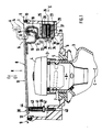
- a motor vehicle body 1 comprises a body recess 2, which serves for the recessed reception of a fuel filler neck 3.
- the filler neck 3 provided at the end with a releasable closure cap 4 is held in position on a bottom wall 6 of the body recess 2 by means of a sealing element 5 made of elastic material.
- a section 7 of the filler neck 3 carrying the closure cap 4 penetrates an opening 8 in the bottom wall 6.
- a pivotable flap 11 is provided which, in its closed position, is flush with the outer skin of the adjacent body surface, a circumferential joint 12 being provided between the edge of the flap 11 and the outer wall 9 of the body.
- the approximately circular flap 11 seen in the embodiment in plan view is articulated to the body recess 2 by means of a hinge 13, the hinge 13 being designed as a lifting hinge, i. that is, in the open position A of the flap 11, the edge region 14 of the flap 11 facing the hinge 13 extends outside the outer wall 9 of the body.
- the hinge 13 comprises two hinge arms 16, 17 connected by a hinge axis 15, each of which has a U-shaped section adjacent to the hinge axis 15.
- the free end of the hinge arm 16 is fixed on the inside of the flap 11.
- the other hinge arm 17 facing the body trough 2 is held in position with the interposition of an adjusting device 18 on the body trough 2.
- a spring member 19 is connected to the hinge arms 16, 17 and holds the flap 11 in the predetermined position both in the open position A and in the closed position B.
- the adjusting device 18 comprises an inner expansion cone 20, an axial clamping element 21, an outer clamping part 22 and a receptacle 23 which is formed in one piece with the body recess 2.
- the preferably cylinder rically formed receptacle 23 has a central axis 24 which runs approximately parallel and at a distance from the bottom wall 6 of the body recess 2.
- the receptacle 23 is open at both ends and has bevels 25 for inserting the adjusting device 18. Seen in plan view, the receptacle 23 is arranged laterally outside the flap 11 (FIG. 2).
- the clamping part 22 and the expansion cone 20 are inserted into the receptacle 23 and are axially displaceable and fixable therein.
- the clamping part 22 which has a cylindrical outer contour, has a through opening for the tensioning element 21 and a frustoconical recess 26 for receiving the expansion cone 20.
- the expansion cone 20 is provided with an internal thread 27 which interacts with an external thread 28 of the tensioning element 21.
- the clamping element 21 which is preferably formed by an adjusting screw, the expansion cone 20 is moved in the direction of a head section 34 of the clamping element 21, as a result of which the outer clamping part 22 is radially expanded and clamped against the inner surface of the receptacle 23.
- the expansion cone 20 and the clamping part 22 are preferably made of plastic.
- the internal thread 27 of the expansion cone 20 is formed by a threaded insert 29 which is inserted into the expansion cone 20.
- an anti-rotation device 30 is provided, which is formed by a molding 31 on the frustoconical clamping part 22 and a corresponding bevel 32 on the expansion cone 20.
- the hinge arm 17 facing the body recess 2 is clamped with its free end between an end face 33 of the clamping part 22 and a disk 35 arranged adjacent to the head section 34.
- the clamping part 22 protrudes on the side facing the filler neck 3 by a small amount from the receptacle 23.
- a bore 36 is provided on the hinge arm 17, the diameter of which is substantially larger than the sharp diameter of the tensioning element 21.
- the screw head 34 extends within the body recess 2 and is freely accessible when the flap 11 is open. 2 for fastening the flap 11 with two spaced-apart receptacles 23 assigned adjusting devices 18, the central axes of the receptacles being identified by the reference numerals 24, 24 ⁇ .
- a metal bearing bush 37 is inserted into the cylindrical receptacle 23, against which the clamping part 22 is clamped by means of the clamping element 21 and the expansion cone 20.
- the flap 11 is displaceable in the direction C-C (longitudinal direction of the vehicle), as a result of which a constant, comprehensive joint 12 can be set between the flap 11 and the adjacent outer wall 9 of the body.
- Adjustment in the direction D-D (vehicle rear direction) and direction E-E (vehicle vertical axis) is ensured by the bore 36 provided on the hinge arm 17.
- a region 38 of the flap 11 facing away from the hinge 13 is supported in the closed position B on a stop element 39 which is adjustable in the vertical direction.
- the stop element 39 which runs approximately perpendicular to a cover plane, is screwed into a through hole 40 of the cross recess 2.
- the stop element 39 comprises a cylindrical inner part 41 with an integrally formed nut 42, an elastic buffer 44 being placed above the nut 42 on a thread section 43 of the inner part 41.
- FIG. 6 shows a further embodiment of an adjusting device 18 for the flap 11.
- the flap 11, the hinge 13, the body recess 2, the stop element 39 and the cylindrical receptacle 23 are of identical design to those in the previously described embodiment.
- the axial clamping element 21 is surrounded by a rubber element 45 which can be inserted into the receptacle 23 and can be displaced and locked in the axial direction.
- a through opening 46 for the tensioning element 21 is provided on the cylindrical rubber element 45.
- the hardness of the rubber element is approximately 80 to 100 Shore A.
- the hinge arm 17 extends between an end face 47 of the rubber element 45 and a washer 49 supported on the head 48 of the tensioning element 21, which has a larger diameter than the head 48 of the tensioning element 21.
- the hinge has adjustability in the DD and EE directions 13 also has a bore 36 with a much larger diameter than the shaft diameter of the clamping element 21.
- a nut 50 is screwed on, which is supported on a circular plate 51 made of metal.
- the circular plate 51 is vulcanized onto the rubber element 45 and has a slightly smaller diameter than the receptacle 23.
Abstract
Eine Klappe zum Verschließen einer Karosseriemulde (2), insbesondere eine Tankklappe (11) für ein Kraftfahrzeug, ist mittels eines Scharniers (13) drehbar angelenkt, wobei ein Scharnierarm an der Karosseriemulde befestigt ist. Um einerseits einen außenhautbündigen Oberflächenübergang von der Klappe zur angrenzenden Karosserieaußenwand zu erzielen und andererseits eine umlaufende, gleichbleibende Fuge zwischen der Klappe und der Karosserieöffnung sicherzustellen, ist der der Karosseriemulde zugekehrte Scharnierarm unter Zwischenschaltung einer Verstelleinrichtung an der Karosseriemulde in Lage gehalten.A flap for closing a body trough (2), in particular a tank flap (11) for a motor vehicle, is pivoted by means of a hinge (13), a hinge arm being attached to the body trough. In order to achieve a surface transition flush with the outer skin from the flap to the adjacent outer wall of the body and to ensure a continuous, constant joint between the flap and the body opening, the hinge arm facing the body trough is held in position with the interposition of an adjustment device on the body trough.
Description
Die Erfindung bezieht sich auf eine Klappe zum Verschließen einer Karosseriemulde, insbesondere eine Tankklappe für ein Kraftfahrzeug, die mittels eines Scharniers drehbar angelenkt ist, wobei ein Scharnierarm an der Karosseriemulde befestigt ist.The invention relates to a flap for closing a body recess, in particular a fuel filler flap for a motor vehicle, which is pivoted by means of a hinge, a hinge arm being fastened to the body recess.
Eine Klappe der eingangs genannten Gattung ist aus der DE-AS 1 907 659 bekannt. Dieser Anordnung haftet der Nachteil an, daß weder an der Klappe noch an der Karosseriemulde Vorkehrungen getroffen worden sind, um einerseits einen außenhautbündigen Verlauf der Klappe sicherzustellen und andererseits eine gleichbleibende umfangsseitige Fuge zwischen der Klappe und der angrenzenden Karosseriewand zu gewährleisten.A flap of the type mentioned is known from DE-AS 1 907 659. This arrangement has the disadvantage that no measures have been taken either on the flap or on the body trough, on the one hand to ensure that the flap runs flush with the outer skin and on the other hand to ensure a constant circumferential joint between the flap and the adjacent body wall.
Das DE-GM 76 31 183 behandelt eine Tankklappe zum Verschließen einer den Kraftstoffeinfüllstutzen von Kraftfahrzeugen aufnehmenden Karosseriemulde, wobei die Tankklappe über ein Schnappgelenk mit der Karosseriemulde verbunden ist. Auf der dem Schnappgelenk abgekehrten Seite ist an der Innenfläche der Tankklappe ein U-förmiges Führungsstück angespritzt, in dem ein Gummipuffer verschiebbar gehalten ist, wobei der Gummipuffer mit einer schrägverlaufenden Fläche der Karosseriemulde in Verschlußstellung der Tankklappe zusammenwirkt.DE-GM 76 31 183 treats a fuel filler flap for closing a body recess receiving the fuel filler neck of motor vehicles, the fuel filler flap being connected to the body recess via a snap joint. On the side facing away from the snap joint, a U-shaped guide piece is injection molded onto the inner surface of the tank flap, in which a rubber buffer is slidably held, the rubber buffer interacting with an inclined surface of the body recess in the closed position of the tank flap.
Dieser Anordnung haftet der Nachteil an, daß durch den Gummipuffer lediglich der dem Schnappgelenk abgekehrte Teilbereich der Tankklappe außenhautbündig eingestellt werden kann, nicht jedoch der dem Schnappgelenk zugekehrte Bereich. Eine gleichbleibende Fuge zwischen der Tankklappe und der angrenzenden Karosserieöffnung läßt sich bei dieser Konstruktion nur schwerlich realisieren.This arrangement has the disadvantage that only the portion of the tank flap facing away from the snap joint can be set flush with the outer skin by the rubber buffer, but not the area facing the snap joint. A constant joint between the tank flap and the adjacent body opening is difficult to achieve with this construction.
Aufgabe der Erfindung ist es, an einer Klappe bzw. einer Karosseriemulde solche Vorkehrungen zu treffen, daß fertigungsbedingte Toleranzen bei der Montage der Klappen in einfacher Weise ausgeglichen werden können, so daß einerseits ein außenhautbündiger Oberflächenübergang von der Klappe zur Karosserie erfolgt und andererseits eine umlaufende, gleichbleibende Fuge zwischen der Klappe und der Karosserieöffnung sichergestellt ist. Ferner soll die Montage der Klappe schnell und einfach durchführbar sein.The object of the invention is to take such measures on a flap or a body trough that manufacturing-related tolerances can be compensated in a simple manner when mounting the flaps, so that on the one hand a surface transition flush with the outer skin from the flap to Bodywork takes place and on the other hand a continuous, constant joint between the flap and the body opening is ensured. Furthermore, the assembly of the flap should be quick and easy to carry out.
Erfindugsgemäß wird diese Aufgabe durch die kennzeichnenden Merkmale des Anspruchs 1 gelöst. Weitere, die Erfindung in vorteilhafter Weise ausgestaltende Merkmale enthallten die Unteransprüche.According to the invention, this object is achieved by the characterizing features of claim 1. Further features which advantageously design the invention contain the subclaims.
Die mit der Erfindung hauptsächlich erzielten Vorteile sind darin zu sehen, daß durch die Anbringung einer Verstelleinrichtung zwischen dem der Karosseriemulde zugekehrten Scharnierarm und der Karosseriemulde bei der Montage eine Justierung der Klappe in sämtlichen Richtungen möglich ist, wodurch sowohl die randseitige Fuge als auch der außenhautbündige Oberflächenverlauf der Klappe zur angrenzenden Karosserie in gewünschter Weise einstellbar ist. Darüber hinaus kann die Klappe schnell und einefach an der Karosseriemulde befestigt werden. Die Bauteile der Verstelleinrichtung lassen sich einfach und kostengünstig herstellen. Das einstellbare Anschlagelement trägt ebenfalls zu einer guten Justierung der Klappe bei.The main advantages achieved with the invention are the fact that by installing an adjusting device between the hinge arm facing the body trough and the body trough during assembly, an adjustment of the flap is possible in all directions, as a result of which both the edge-side joint and the surface surface flush with the outer skin the flap to the adjacent body is adjustable in the desired manner. In addition, the flap can be quickly and easily attached to the body recess. The components of the adjustment device can be manufactured simply and inexpensively. The adjustable stop element also contributes to a good adjustment of the flap.
Ein Ausführungsbeispiel der Erfindung ist in der Zeichnung dargestellt und wird im folgenden näher erläutert.An embodiment of the invention is shown in the drawing and is explained in more detail below.
Es zeigt
- Fig. 1 einen HorizontaLschnitt durch eine Klappe zusammen mit einer einen Kraftstoffeninfüllstutzen aufnehmenden Karosseriemulde,
- Fig. 2 eine Ansicht in Pfeilrichtung R der Fig. 1 auf die Karosseriemulde,
- Fig. 3 eine Ansicht in Pfeilrichtung S der Fig. 1 mit der erfindungsgemäßen Verstelleinrichtung,
- Fig. 4 einen Schnitt nach der Linie IV-IV der Fig. 3, der das Klemmteil zeigt,
- Fig. 5 einen Schnitt nach der Linie V-V der Fig. 3, der den Spreizkegel zeigt,
- Fig. 6 einen Schnitt entsprechend Fig. 1 mit einer weiteren Ausführungsform einer Verstelleinrichtung.
- 1 shows a horizontal section through a flap together with a body recess receiving a fuel filler neck,
- 2 is a view in the direction of arrow R of FIG. 1 on the body trough,
- 3 is a view in the direction of arrow S of FIG. 1 with the adjusting device according to the invention,
- 4 shows a section along the line IV-IV of FIG. 3, showing the clamping part,
- 5 shows a section along the line VV of FIG. 3, showing the expansion cone,
- 6 shows a section corresponding to FIG. 1 with a further embodiment of an adjusting device.
Eine Kraftfahrzeug-Karosserie 1 umfaßt im dargestellten Bereich eine Karosseriemulde 2, die zur versenkten Aufnahme eines Kraftstoffeinfüllstutzens 3 dient. Der endseitig mit einem lösbaren Verschlußdeckel 4 versehene Einfüllstutzen 3 ist unter Vermittlung eines aus elastischem Werkstoff bestehenden Dichtelementes 5 an einer Bodenwand 6 der Karosseriemulde 2 in Lage gehalten. Ein den Verschlußdeckel 4 tragender Abschnitt 7 des Einfüllstutzens 3 durchdringt eine Öffnung 8 der Bodenwand 6.In the area shown, a motor vehicle body 1 comprises a
Die Karosseriemulde 2 wird gemäß Fig. 1 durch ein vorzugsweise aus Kunststoff hergestelltes, topfförmiges Bauteil gebildet, dans an die Innen seite der angrenzenden Karosserieaußenwand 9 aufgesetzt und durch ein Klebeelement 10 mit dieser verbunden ist. Zur Abdeckung des Einfüllstutzens 3 ist eine schewenkbare Klappe 11 vorgesehen, die in ihrer Schließstellung außenhautbündig zur angrenzenden Karosserieoberfläche verläuft, wobei zwischen dem Rand der Klappe 11 und der Karosserieaußenwand 9 eine umlaufende Fuge 12 vorgeshen ist. Die im Ausführungsbeispiel in der Draufsicht gesehen etwa kreisrunde Klappe 11 ist unter Vermittlung eines Scharniers 13 an der Karosseriemulde 2 angelenkt, wobei das Scharnier 13 als aushebendes Scharnier ausgebildet ist, d. h., in Offenstellung A der Klappe 11 erstreckt sich der dem Scharnier 13 zugekehrte Randbereich 14 der Klappe 11 außerhalb der Karosserieaußenwand 9.1 is formed by a cup-shaped component, preferably made of plastic, which is placed on the inside of the adjacent
Das Scharnier 13 umfaßt zwei durch eine Scharnierachse 15 verbundene Scharnierarme 16, 17, die jeweils benachbart der Scharnierachse 15 einen U-förmigen Abschnitt aufweisen. Der Scharnierarm 16 ist mit seinem freien Ende an der Innenseite der Klappe 11 festgelegt. Der andere, der Karosseriemulde 2 zugekehrte Scharnierarm 17 ist unter Zwischenschaltung einer Verstelleinrichtung 18 an der Karosseriemulde 2 in Lage gehalten. Mit den Scharnierarmen 16, 17 verbunden ist ein Federglied 19, das die Klappe 11 sowohl in der Offenstellung A als auch in der Schließstellung B in der vorbestimmten Lage hält.The
Die Verstelleinrichtung 18 umfaßt einen inneren Spreizkegel 20, ein axiales Spannelement 21, ein äußeres Klemmteil 22 und eine Aufnahme 23, die einstückig mit der Karosseriemulde 2 ausgebildet ist. Die vorzugsweise zylind risch augebildete Aufnahme 23 weist einen Mittelachse 24 auf, die etwa parallel und mit Abstand zur Bodenwand 6 der Karosseriemulde 2 verläuft. Die Aufnahme 23 ist an ihren beiden Enden offen ausgebildet und weist Anfasungen 25 zum Einführen der Verstelleinrichtung 18 auf. In der Draufsicht gesehen, ist die Aufnahme 23 seitlich außerhalb der Klappe 11 angeordnet (Fig. 2). Das Klemmteil 22 und der Spreizkegel 20 werden in die Aufnahme 23 eingeführt und sind darin axial verschiebbar und festlegbar. Das eine zylindrische Außenkontur aufweisende Klemmteil 22 besitzt eine Durchgangsöffnung für das Spannelement 21 und eine kegelstumpfförmige Ausnehmung 26 zur Aufnahme des spreizkegels 20. Der Spreizkegel 20 ist mit einem Innengewinde 27 versehen, das mit einem Außengewinde 28 des Spannelementes 21 zusammenwirkt. Durch Drehen des Spannelementes 21, das vorzugsweise durch eine Stellschraube gebildet wird, wird der Spreizkegel 20 in Richtung eines Kopfabschnittes 34 des Spannelementes 21 bewegt, wodurch das äußere Klemmteil 22 radial aufgeweitet und gegen die Innenfläche der Aufnahme 23 gespannt wird. Der Spreizkegel 20 und das Klemmteil 22 sind vorzugsweise aus Kunststoff gefertigt.The adjusting
Gemäß Fig. 5 wird das Innengewinde 27 des Spreizkegels 20 durch einen Gewindeeinsatz 29 gebildet, der in den Spreizkegel 20 eingesetzt ist. Zwischen dem Spreizkegel 20 und dem Klemmteil 22 ist eine Verdrehsicherung 30 vorgesehen, die durch eine Anformung 31 am kegelstumpfförmigen Klemmteil 22 und eine korrespondierende Schräge 32 am Spreizkegel 20 gebildet wird. Der der Karosseriemulde 2 zugekehrte Scharnierarm 17 ist mit seinem freien Ende zwischen eienr Stirnseite 33 des Klemmteils 22 und einer benachbart dem Kopfabschnitt 34 angeordneten Scheibe 35 eingespannt. Das Klemmteil 22 ragt auf der dem Einfüllstutzen 3 zugekehrten Seite um einen geringen Betrag aus der Aufnahme 23 heraus. Zum Hindurcführen des Spannelementes 21 ist am Scharnierarm 17 eine Bohrung 36 vorgesehen, deren Durchmesser wesentlich größer ist als der Scharftdurchmesser des Spannelementes 21.5, the
Der Schraubenkopf 34 erstreckt sich innerhalb der Karosseriemulde 2 und ist bei geöffneter Klappe 11 frei zugänglich. Gemäß Fig. 2 zum Befestigen der Klappe 11 zwei mit Abstand zueinander verlaufende Aufnahmen 23 mit zugeordneten Verstelleinrichtungen 18 vogesehen, wobei die Mittelachsen der Aufnahmen mit den Bezugszeichne, 24, 24ʹ gekennzeichnet sind.The
Entsprechend Fig. 1 ist in die zylindrische Aufnahme 23 eine Lagerbuchse 37 aus Metall eingesetzt, gegen die das Klemmteil 22 mittels des Spannelements 21 und des Spreizkegels 20 gespannt wird. Durch das Klemmteil 22, das Spannelement 21 und den Spreizkegel 20 ist die Klappe 11 in Richtung C-C (Fahrzeuglängsrichtung) verschiebbar, wodurch sich eine gleichbleibende, umfasseitige Fuge 12 zwischen der Klappe 11 und der angrenzenden Karosserieaußenwand 9 einstellen läßt. Eine Einstellbarkeit in Richtung D-D (Fahrzeugguerrichtung) und Richtung E-E (Fahrzeughochachse) wird durch die am Scharnierarm 17 angebrachte Bohrung 36 gewährleistet.According to FIG. 1, a metal bearing
Ein dem Scharnier 13 abgekehrter Bereich 38 der Klappe 11 stützt sich in der Schließstellung B an einem in Höhnrichtung einstellbar ausgebildeten Anschlagelement 39 ab. Das etwa senkrecht zu einer Deckelebene verlaufende Anshclagelement 39 ist in eine Durchgangsbohrung 40 der Krosseriemulde 2 eingedreht. Das Anschlagelement 39 umfaßt ein zylkindrisches Innenteil 41 mit einer angeformten Mutter 42, wobei oberhalb der Mutter 42 auf einem Gwindeabschnitt 43 des Innenteils 41 ein elastischer Puffer 44 aufgesetzt ist.A
In Fig. 6 ist eine weitere Ausführungsform einer Verstelleinrichtung 18 für die Klappe 11 dargestellt. Die Klappe 11, das Scharnier 13, die Karosseriemulde 2, das Anschlagelement 39 sowie die zylindrische Aufnahme 23 sind dabei identisch ausgebildet wie bei der zuvor beschriebenen Ausführung. Anstelle des Spreizkegels 20 und des Klemmteiles 22 ist das axiale Spannelement 21 von einem Gummielement 45 umgeben, das in die Aufnahme 23 einsetzbar und in axialer Richtung verschiebbar und feststellbar ist. Am zylindrischen Gummielement 45 ist eine Durchführöffnung 46 für das Spannelement 21 vorgesehen. Die Härte des Gummielement beträgt etwa 80 bis 100 Shore A. Durch Anziehen des Spannelementes 21 wird das Gummielement 45 radial aufgeweitet und verspannt sich mit der Aufnahme 23.6 shows a further embodiment of an adjusting
Der Scharnierarm 17 erstreckt sich zwischen einer Stirnseite 47 des Gummielementes 45 und einer sich am Kopf 48 des Spannelementes 21 abstützenden Scheibe 49, wobei diese einen größeren Durchmesser aufweist als der Kopf 48 des Spannelementes 21. Zur Einstellbarkeit in Richtung D-D und Richtung E-E weist das Scharnier 13 ebenfalls eine Bohrung 36 mit einem wesentlich größeren Durchmesser auf als der Schaftdurchmesser des Spannelementes 21.The
Auf das Kopf des Spannelementes 21 abgekehrte Ende ist eine Mutter 50 aufgedreht, die sich an einer kreisförmigen Platte 51 aus Metall abstützt. Die kreisförmige Platte 51 ist auf das Gummielement 45 aufvulkanisiert und weist einen geringfügig kleineren Durchmesser auf als die Aufnahme 23.On the head facing away from the
Claims (16)
Applications Claiming Priority (2)
| Application Number | Priority Date | Filing Date | Title |
|---|---|---|---|
| DE3702903 | 1987-01-31 | ||
| DE19873702903 DE3702903A1 (en) | 1987-01-31 | 1987-01-31 | FLAP FOR CLOSING A BODY PAN |
Publications (3)
| Publication Number | Publication Date |
|---|---|
| EP0277294A2 true EP0277294A2 (en) | 1988-08-10 |
| EP0277294A3 EP0277294A3 (en) | 1988-12-21 |
| EP0277294B1 EP0277294B1 (en) | 1991-01-16 |
Family
ID=6319950
Family Applications (1)
| Application Number | Title | Priority Date | Filing Date |
|---|---|---|---|
| EP87116903A Expired - Lifetime EP0277294B1 (en) | 1987-01-31 | 1987-11-17 | Lid for closing a vehicle body hollow |
Country Status (4)
| Country | Link |
|---|---|
| US (1) | US4811984A (en) |
| EP (1) | EP0277294B1 (en) |
| JP (1) | JPS63188522A (en) |
| DE (2) | DE3702903A1 (en) |
Cited By (6)
| Publication number | Priority date | Publication date | Assignee | Title |
|---|---|---|---|---|
| FR2664864A1 (en) * | 1990-07-19 | 1992-01-24 | Omegal | Flap for closing off access to the fuel tank of a motor vehicle |
| AT402625B (en) * | 1995-11-07 | 1997-07-25 | Blau Automobiltechnik Gmbh | Closure device for a filler neck of a vehicle tank |
| EP0796755A1 (en) * | 1996-03-21 | 1997-09-24 | Mittelhäuser, Bernhard | Tank flap for filler neck covering |
| DE19842690B4 (en) * | 1998-09-17 | 2009-02-12 | Volkswagen Ag | Covering device for an opening, in particular a body opening of a motor vehicle, with a flap |
| FR3077535A1 (en) * | 2018-02-07 | 2019-08-09 | Psa Automobiles Sa | FUEL OR DEPOLLUTION SUPPLY ASSEMBLY OF A MOTOR VEHICLE |
| DE102020216596A1 (en) | 2020-02-20 | 2021-08-26 | Bos Gmbh & Co. Kg | Device for adjusting a body panel of a movable body part of a motor vehicle |
Families Citing this family (27)
| Publication number | Priority date | Publication date | Assignee | Title |
|---|---|---|---|---|
| JP2918116B2 (en) * | 1989-06-22 | 1999-07-12 | ヤマハ発動機株式会社 | Fuel supply structure of scooter type motorcycles and tricycles |
| US5044678A (en) * | 1990-07-25 | 1991-09-03 | Lectron Products, Inc. | Solenoid operated latch device with movable pole piece |
| US5165749A (en) * | 1991-07-22 | 1992-11-24 | Molmec, Inc. | Gas cap cover adjustment device |
| JPH06349544A (en) * | 1993-06-14 | 1994-12-22 | Sumitomo Wiring Syst Ltd | Charge connector structure for vehicle |
| US5437491A (en) * | 1994-04-07 | 1995-08-01 | Illinois Tool Works Inc. | Fuel door housing |
| US5513832A (en) * | 1994-04-22 | 1996-05-07 | Lectron Products, Inc. | Variable force solenoid valve |
| DE19514388C2 (en) * | 1995-04-19 | 2002-04-18 | Scharwaechter Gmbh Co Kg | Door or flap hinge for motor vehicles |
| DE19517705C2 (en) * | 1995-05-13 | 1998-11-05 | Itw Ateco Gmbh | Fuel tank |
| DE19628878A1 (en) * | 1996-05-23 | 1998-02-12 | Bayerische Motoren Werke Ag | Control method for an internal combustion engine |
| US5836638A (en) * | 1996-12-09 | 1998-11-17 | Illinois Tool Works Inc. | Fuel door assembly |
| DE29710918U1 (en) * | 1997-06-23 | 1997-08-14 | Itw Ateco Gmbh | Fuel filler flap |
| DE59802712D1 (en) * | 1998-05-23 | 2002-02-21 | Ford Global Tech Inc | Remote unlocking for a tank filler body flap for passenger cars |
| US6318771B1 (en) | 1999-07-22 | 2001-11-20 | Stoneridge Control Devices, Inc. | Fuel filler door actuator |
| US6189959B1 (en) | 1999-12-08 | 2001-02-20 | Daimlerchrysler Corporation | Door adjusting bumper providing show surface alignment |
| DE102005007416B4 (en) * | 2005-02-18 | 2017-08-17 | SMR Patents S.à.r.l. | Tank cap for a motor vehicle |
| CA2516139C (en) * | 2005-08-15 | 2011-03-15 | Van-Rob Inc. | Automotive fuel door assembly |
| DE102006015418B4 (en) * | 2006-04-03 | 2013-01-24 | Audi Ag | Tank flap module and method for producing a tank flap module |
| DE102006015398B4 (en) * | 2006-04-03 | 2012-10-31 | Audi Ag | Tank flap module and method for attaching a tank flap module to a body |
| US8162375B2 (en) * | 2008-01-25 | 2012-04-24 | Illinois Tool Works Inc. | Hinge mounted fuel housing seal |
| JP5711471B2 (en) * | 2010-05-24 | 2015-04-30 | 株式会社城南製作所 | Charge port lid assembly |
| JP5678474B2 (en) * | 2010-05-25 | 2015-03-04 | スズキ株式会社 | Charging connector |
| WO2011155263A1 (en) * | 2010-06-08 | 2011-12-15 | スズキ株式会社 | Vehicle bezel attachment structure |
| CA2805662C (en) * | 2010-10-12 | 2014-04-22 | Kabushiki Kaisha Tokai Rika Denki Seisakusho | Device for detecting opening/closing of charger lid |
| DE102011004556A1 (en) | 2011-02-23 | 2012-08-23 | Ford Global Technologies, Llc | tank recess |
| DE102012102685B4 (en) | 2012-03-28 | 2024-02-01 | Dr. Ing. H.C. F. Porsche Aktiengesellschaft | Device for holding a container for a charging socket in a motor vehicle |
| CN104717853B (en) * | 2013-12-11 | 2018-03-20 | 光宝电子(广州)有限公司 | Have the sub-assembly of liftable lid and its moveable rotary axis module |
| US10086693B2 (en) * | 2016-06-14 | 2018-10-02 | Nissan North America, Inc. | Fuel cap barrier kit |
Citations (5)
| Publication number | Priority date | Publication date | Assignee | Title |
|---|---|---|---|---|
| DE1907659B2 (en) * | 1969-02-15 | 1973-09-06 | Volkswagenwerk Ag, 3180 Wolfsburg | CLOSURE FOR THE COVER FLAP OF A BODY BODY THAT RECEIVES THE FUEL FILLER NECK OF MOTOR VEHICLES |
| DE7631183U1 (en) * | 1976-10-06 | 1977-02-03 | Adam Opel Ag, 6090 Ruesselsheim | Hinged lid for closing a body cavity that accommodates the fuel filler neck of motor vehicles |
| EP0096604A1 (en) * | 1982-05-25 | 1983-12-21 | Automobiles Citroen | Tank filler spout, in particular for motor vehicles |
| FR2538785A2 (en) * | 1982-07-02 | 1984-07-06 | Neiman Diffusion | Lockable stopper device for tank filler nozzle |
| DE3301072A1 (en) * | 1983-01-14 | 1984-07-19 | Itw-Ateco Gmbh, 2000 Norderstedt | Filler inlet compartment for motor vehicles |
Family Cites Families (17)
| Publication number | Priority date | Publication date | Assignee | Title |
|---|---|---|---|---|
| BE334197A (en) * | 1925-05-19 | |||
| CH223124A (en) * | 1940-09-27 | 1942-08-31 | Tissages A Brechard Sa D | Method of fixing an organ on a tree. |
| US2865653A (en) * | 1956-09-21 | 1958-12-23 | Gen Motors Corp | Access door for vehicle fuel inlet |
| DE1743826U (en) * | 1957-02-25 | 1957-04-25 | Gummi Hagemann Helmut Hagemann | FITTING FOR THE ATTACHMENT OF SUPPORT RODS AND LIKE. |
| US3483586A (en) * | 1968-03-25 | 1969-12-16 | Kenneth William Watson | Adjustable hinge device |
| US3561798A (en) * | 1969-10-13 | 1971-02-09 | Allis Chalmers Mfg Co | Disconnect switch having internally clamped rotary coupling |
| US3584473A (en) * | 1969-11-19 | 1971-06-15 | Uniroyal Inc | Force-transmitting systems |
| DE2242822A1 (en) * | 1972-08-31 | 1974-03-14 | Scharwaechter Kg | LEAF SPRING ARRANGEMENT FOR LID OR FLAPS FOR CLOSING OPENINGS OR RECESSES IN MOTOR VEHICLE BODIES |
| US3841771A (en) * | 1972-12-26 | 1974-10-15 | Caterpillar Tractor Co | Tapered hinge pin assembly and removal means |
| US3870361A (en) * | 1973-02-12 | 1975-03-11 | Atwood Vacuum Machine Co | Hinging system for automobile doors with hinge halves welded to body and door |
| US3915491A (en) * | 1974-06-21 | 1975-10-28 | Tom C Montgomery | Remote controlled gas tank lock |
| US3992051A (en) * | 1975-11-19 | 1976-11-16 | Ronald James Hitch | Protector for automobile fuel tank filler neck |
| DE2852855C2 (en) * | 1978-12-07 | 1984-04-12 | Ford-Werke AG, 5000 Köln | Closure flap for covering a body opening of a motor vehicle |
| DE2937166A1 (en) * | 1979-09-14 | 1981-04-02 | Audi Nsu Auto Union Ag | Concealed hinge for rear flap of car - has swan neck support with mounting bolts accessed from inside car |
| CH645155A5 (en) * | 1980-02-15 | 1984-09-14 | Walter Pfaeffli | DOOR BAND. |
| GB2093517B (en) * | 1981-02-21 | 1986-01-02 | Ibrahim Kemal | Securing means |
| US4527825A (en) * | 1983-11-17 | 1985-07-09 | General Motors Corporation | Fuel filler door with dual hinge |
-
1987
- 1987-01-31 DE DE19873702903 patent/DE3702903A1/en active Granted
- 1987-11-17 DE DE8787116903T patent/DE3767471D1/en not_active Expired - Lifetime
- 1987-11-17 EP EP87116903A patent/EP0277294B1/en not_active Expired - Lifetime
- 1987-12-28 JP JP62330326A patent/JPS63188522A/en active Pending
-
1988
- 1988-01-25 US US07/148,355 patent/US4811984A/en not_active Expired - Fee Related
Patent Citations (5)
| Publication number | Priority date | Publication date | Assignee | Title |
|---|---|---|---|---|
| DE1907659B2 (en) * | 1969-02-15 | 1973-09-06 | Volkswagenwerk Ag, 3180 Wolfsburg | CLOSURE FOR THE COVER FLAP OF A BODY BODY THAT RECEIVES THE FUEL FILLER NECK OF MOTOR VEHICLES |
| DE7631183U1 (en) * | 1976-10-06 | 1977-02-03 | Adam Opel Ag, 6090 Ruesselsheim | Hinged lid for closing a body cavity that accommodates the fuel filler neck of motor vehicles |
| EP0096604A1 (en) * | 1982-05-25 | 1983-12-21 | Automobiles Citroen | Tank filler spout, in particular for motor vehicles |
| FR2538785A2 (en) * | 1982-07-02 | 1984-07-06 | Neiman Diffusion | Lockable stopper device for tank filler nozzle |
| DE3301072A1 (en) * | 1983-01-14 | 1984-07-19 | Itw-Ateco Gmbh, 2000 Norderstedt | Filler inlet compartment for motor vehicles |
Cited By (7)
| Publication number | Priority date | Publication date | Assignee | Title |
|---|---|---|---|---|
| FR2664864A1 (en) * | 1990-07-19 | 1992-01-24 | Omegal | Flap for closing off access to the fuel tank of a motor vehicle |
| AT402625B (en) * | 1995-11-07 | 1997-07-25 | Blau Automobiltechnik Gmbh | Closure device for a filler neck of a vehicle tank |
| EP0796755A1 (en) * | 1996-03-21 | 1997-09-24 | Mittelhäuser, Bernhard | Tank flap for filler neck covering |
| DE19842690B4 (en) * | 1998-09-17 | 2009-02-12 | Volkswagen Ag | Covering device for an opening, in particular a body opening of a motor vehicle, with a flap |
| FR3077535A1 (en) * | 2018-02-07 | 2019-08-09 | Psa Automobiles Sa | FUEL OR DEPOLLUTION SUPPLY ASSEMBLY OF A MOTOR VEHICLE |
| WO2019155142A1 (en) * | 2018-02-07 | 2019-08-15 | Psa Automobiles Sa | Assembly for supplying fuel or pollution control product to a motor vehicle |
| DE102020216596A1 (en) | 2020-02-20 | 2021-08-26 | Bos Gmbh & Co. Kg | Device for adjusting a body panel of a movable body part of a motor vehicle |
Also Published As
| Publication number | Publication date |
|---|---|
| DE3767471D1 (en) | 1991-02-21 |
| JPS63188522A (en) | 1988-08-04 |
| EP0277294B1 (en) | 1991-01-16 |
| DE3702903C2 (en) | 1992-03-19 |
| DE3702903A1 (en) | 1988-08-11 |
| US4811984A (en) | 1989-03-14 |
| EP0277294A3 (en) | 1988-12-21 |
Similar Documents
| Publication | Publication Date | Title |
|---|---|---|
| EP0277294B1 (en) | Lid for closing a vehicle body hollow | |
| EP3408547B1 (en) | Alignment element for positioning an attachment part | |
| DE3328338A1 (en) | Device for adjusting a first component relative to a second component | |
| DE2838520A1 (en) | VEHICLE REAR VIEW MIRROR | |
| DE102021118920A1 (en) | tolerance compensation device | |
| DE10213131C1 (en) | Hinge for motor vehicle boot lid has studs on lid exterior fitting into holes in hinge arm pivoted to bodywork | |
| EP0527455B1 (en) | Support for the exterior rear view mirror of a utility vehicle | |
| DE60308364T2 (en) | Device for adjusting the side of a window regulator for motor vehicles | |
| EP1793052B1 (en) | In- and overflow fitting for bath tubs | |
| DE102005046325B4 (en) | Device for attaching a wiper functional unit to a wiper shaft | |
| EP0215281B1 (en) | Bearing for a window, door or similar wing | |
| EP2167354B1 (en) | Fastening arrangement | |
| DE2343370A1 (en) | PROTECTIVE COVER FOR A WIPER DRIVE | |
| DE19811163A1 (en) | Cover for headlamp cleaning unit on vehicle | |
| DE19643407A1 (en) | Automotive car boot or bonnet mounting spacer | |
| DE4142598C1 (en) | Glove pocket lid hinge - has fastener plate allocated to body-fixed tap with straps allowing plate to move in two dimensions relative to support | |
| AT390818B (en) | FURNITURE HINGE | |
| DE3807703C1 (en) | Hinge for vehicles | |
| DE3644492C2 (en) | ||
| DE19855949C1 (en) | Estate car tailgate and rear window swings up and down with a buffer at the bodywork edges which can be adjusted for height while the tailgate is closed | |
| DE3243831C1 (en) | Mounting for hinge arms of wings, especially of four-bar coupling mechanisms for the pivotable fastening of covering hoods | |
| DE3511811C2 (en) | Cleaning device, in particular for windows of motor vehicles | |
| DE202004003237U1 (en) | Device for lashing luggage parts in a motor vehicle | |
| DE19943619A1 (en) | Window pane adjuster for frameless vehicle doors has displacement bolt passing vertically through follower moving vertically in guide rail and with upper coupling end coupled to lower end of pane and movable transversely | |
| DE3400660A1 (en) | Closure head for containers |
Legal Events
| Date | Code | Title | Description |
|---|---|---|---|
| PUAI | Public reference made under article 153(3) epc to a published international application that has entered the european phase |
Free format text: ORIGINAL CODE: 0009012 |
|
| AK | Designated contracting states |
Kind code of ref document: A2 Designated state(s): DE FR GB IT |
|
| PUAL | Search report despatched |
Free format text: ORIGINAL CODE: 0009013 |
|
| AK | Designated contracting states |
Kind code of ref document: A3 Designated state(s): DE FR GB IT |
|
| 17P | Request for examination filed |
Effective date: 19890421 |
|
| 17Q | First examination report despatched |
Effective date: 19900427 |
|
| ITF | It: translation for a ep patent filed |
Owner name: DE DOMINICIS & MAYER S.R.L. |
|
| GRAA | (expected) grant |
Free format text: ORIGINAL CODE: 0009210 |
|
| AK | Designated contracting states |
Kind code of ref document: B1 Designated state(s): DE FR GB IT |
|
| GBT | Gb: translation of ep patent filed (gb section 77(6)(a)/1977) | ||
| REF | Corresponds to: |
Ref document number: 3767471 Country of ref document: DE Date of ref document: 19910221 |
|
| ET | Fr: translation filed | ||
| PLBE | No opposition filed within time limit |
Free format text: ORIGINAL CODE: 0009261 |
|
| STAA | Information on the status of an ep patent application or granted ep patent |
Free format text: STATUS: NO OPPOSITION FILED WITHIN TIME LIMIT |
|
| 26N | No opposition filed | ||
| PGFP | Annual fee paid to national office [announced via postgrant information from national office to epo] |
Ref country code: DE Payment date: 19921103 Year of fee payment: 6 |
|
| PGFP | Annual fee paid to national office [announced via postgrant information from national office to epo] |
Ref country code: GB Payment date: 19921106 Year of fee payment: 6 |
|
| PGFP | Annual fee paid to national office [announced via postgrant information from national office to epo] |
Ref country code: FR Payment date: 19921130 Year of fee payment: 6 |
|
| PG25 | Lapsed in a contracting state [announced via postgrant information from national office to epo] |
Ref country code: GB Effective date: 19931117 |
|
| GBPC | Gb: european patent ceased through non-payment of renewal fee |
Effective date: 19931117 |
|
| PG25 | Lapsed in a contracting state [announced via postgrant information from national office to epo] |
Ref country code: FR Effective date: 19940729 |
|
| PG25 | Lapsed in a contracting state [announced via postgrant information from national office to epo] |
Ref country code: DE Effective date: 19940802 |
|
| REG | Reference to a national code |
Ref country code: FR Ref legal event code: ST |
|
| PG25 | Lapsed in a contracting state [announced via postgrant information from national office to epo] |
Ref country code: IT Free format text: LAPSE BECAUSE OF NON-PAYMENT OF DUE FEES;WARNING: LAPSES OF ITALIAN PATENTS WITH EFFECTIVE DATE BEFORE 2007 MAY HAVE OCCURRED AT ANY TIME BEFORE 2007. THE CORRECT EFFECTIVE DATE MAY BE DIFFERENT FROM THE ONE RECORDED. Effective date: 20051117 |