EP0274003B1 - Système d'admission interne d'électrolyte pour le transport fiable à travers une batterie de cellules à combustible - Google Patents
Système d'admission interne d'électrolyte pour le transport fiable à travers une batterie de cellules à combustible Download PDFInfo
- Publication number
- EP0274003B1 EP0274003B1 EP87111437A EP87111437A EP0274003B1 EP 0274003 B1 EP0274003 B1 EP 0274003B1 EP 87111437 A EP87111437 A EP 87111437A EP 87111437 A EP87111437 A EP 87111437A EP 0274003 B1 EP0274003 B1 EP 0274003B1
- Authority
- EP
- European Patent Office
- Prior art keywords
- electrolyte
- fuel cell
- flow
- plates
- cell stack
- Prior art date
- Legal status (The legal status is an assumption and is not a legal conclusion. Google has not performed a legal analysis and makes no representation as to the accuracy of the status listed.)
- Expired - Lifetime
Links
Images


Classifications
-
- H—ELECTRICITY
- H01—ELECTRIC ELEMENTS
- H01M—PROCESSES OR MEANS, e.g. BATTERIES, FOR THE DIRECT CONVERSION OF CHEMICAL ENERGY INTO ELECTRICAL ENERGY
- H01M8/00—Fuel cells; Manufacture thereof
- H01M8/04—Auxiliary arrangements, e.g. for control of pressure or for circulation of fluids
- H01M8/04276—Arrangements for managing the electrolyte stream, e.g. heat exchange
- H01M8/04283—Supply means of electrolyte to or in matrix-fuel cells
-
- H—ELECTRICITY
- H01—ELECTRIC ELEMENTS
- H01M—PROCESSES OR MEANS, e.g. BATTERIES, FOR THE DIRECT CONVERSION OF CHEMICAL ENERGY INTO ELECTRICAL ENERGY
- H01M8/00—Fuel cells; Manufacture thereof
- H01M8/24—Grouping of fuel cells, e.g. stacking of fuel cells
- H01M8/241—Grouping of fuel cells, e.g. stacking of fuel cells with solid or matrix-supported electrolytes
-
- H—ELECTRICITY
- H01—ELECTRIC ELEMENTS
- H01M—PROCESSES OR MEANS, e.g. BATTERIES, FOR THE DIRECT CONVERSION OF CHEMICAL ENERGY INTO ELECTRICAL ENERGY
- H01M8/00—Fuel cells; Manufacture thereof
- H01M8/24—Grouping of fuel cells, e.g. stacking of fuel cells
- H01M8/2465—Details of groupings of fuel cells
- H01M8/2483—Details of groupings of fuel cells characterised by internal manifolds
-
- H—ELECTRICITY
- H01—ELECTRIC ELEMENTS
- H01M—PROCESSES OR MEANS, e.g. BATTERIES, FOR THE DIRECT CONVERSION OF CHEMICAL ENERGY INTO ELECTRICAL ENERGY
- H01M8/00—Fuel cells; Manufacture thereof
- H01M8/24—Grouping of fuel cells, e.g. stacking of fuel cells
- H01M8/2465—Details of groupings of fuel cells
- H01M8/2484—Details of groupings of fuel cells characterised by external manifolds
-
- Y—GENERAL TAGGING OF NEW TECHNOLOGICAL DEVELOPMENTS; GENERAL TAGGING OF CROSS-SECTIONAL TECHNOLOGIES SPANNING OVER SEVERAL SECTIONS OF THE IPC; TECHNICAL SUBJECTS COVERED BY FORMER USPC CROSS-REFERENCE ART COLLECTIONS [XRACs] AND DIGESTS
- Y02—TECHNOLOGIES OR APPLICATIONS FOR MITIGATION OR ADAPTATION AGAINST CLIMATE CHANGE
- Y02E—REDUCTION OF GREENHOUSE GAS [GHG] EMISSIONS, RELATED TO ENERGY GENERATION, TRANSMISSION OR DISTRIBUTION
- Y02E60/00—Enabling technologies; Technologies with a potential or indirect contribution to GHG emissions mitigation
- Y02E60/30—Hydrogen technology
- Y02E60/50—Fuel cells
Definitions
- This invention relates generally to a stack of fuel cells which convert the latent chemical energy of a fuel into electricity directly and, more particularly, is concerned with an internal electrolyte supply system for reliable transport of electrolyte throughout the fuel cell stack.
- One common fuel cell system includes a plurality of sub-assemblies which except for the top and bottom sub-assemblies, each include two bipolar plates between which is supported two gas electrodes, one an anode and the other a cathode, and a matrix with an ion-conductive electrolyte, such as phosphoric acid, between the anode and cathode electrodes.
- the sub-assemblies herein referred to as fuel cells, are oriented one atop another and electrically connected in series (alternate electron and ion paths) to form a fuel cell stack.
- the top end plate of the top sub-assembly and the bottom end plate of the bottom sub-assembly are each half-bipolar plates.
- Process gases such as a fuel and an oxidant are supplied respectively to the anode and cathode electrodes via manifolds attached to the stack and channels defined in the bipolar plates.
- the fuel in the form of hydrogen atoms when supplied to the anode electrode dissociates into hydrogen ions and electrons.
- the electrons are transmitted from the anode electrode of a given cell across one bipolar plate to the cathode electrode of an adjacent cell, while the hydrogen ions migrate directly through the acidic electrolyte to the cathode electrode of the given cell, where they react with electrons transmitted to the cathode electrode across the other bipolar plate from the anode electrode of the other adjacent cell and with oxygen to form water. This is repeated at and between the cells throughout the stack with electrons then transferring from the last cathode electrode at one end of the stack to the last anode electrode at the other end of the stack in the form of an electrical current through an external circuit where useful work is produced.
- the above-described phosphoric acid fuel cell stack for generating electric power is made up of hundreds of stacked plates, a majority being bipolar plates and a minority being cooling plates, which form a column approximately eight feet in height.
- Each anode electrode is located on the top side of a bipolar plate facing upward, whereas each cathode electrode is located on the bottom side thereof facing downward.
- Electrolyte is supplied to the fuel cells in the stack through fill holes at the top of the stack.
- Most of the plates have electrolyte flow grooves defined on the top surface along a pair of the opposite edges of the plate. These grooves are located below the matrix which is positioned between the electrodes of the cell and distribute the electrolyte across the cell.
- the plates have vertical holes defined therethrough at selected ends of the grooves such that the grooves and holes form a pair of internal independent serpentine feed paths of electrolyte flow from the top fill holes downward through the fuel cell stack.
- Similar internal electrolyte supply systems with single serpentine feed path configurations are disclosed in above-cited U.S. Patent 4,383,009 and first application cross-referenced above, although in these systems the grooves are located such that the electrolyte flow path is above the matrix.
- the present invention resides in a fuel cell stack having electrolyte feed and drain means and a plurality of stacked fuel cells, each fuel cell including bipolar plates separating said fuel cell from adjacent fuel cells in said stack thereof and an electrolyte-containing matrix disposed between said plates, and an internal electrolyte supply system interconnecting said feed and drain means, characterized in that said system comprises: (a) first means defined repeatedly throughout the fuel cell stack for flowing electrolyte along a series of first paths each extending horizontally and directly through at least one of the cells in the stack between the plates thereof so as to expose the electrolyte to the matrix of the cell; (b) second means defined repeatedly throughout the fuel cell stack for flowing electrolyte along a series of second paths extending through the plates of the cell stack at opposite ends of the first horizontal paths and forming pools of electrolyte by means of dams or steps and the paths, the second paths being in communicative flow relation to the first paths and adapted to supply electrolyte in by-pass fashion directly to the respective first paths; and
- the first means includes at least one electrolyte flow groove defined in one side of one of the plates of each cell of the stack.
- an electrolyte transport wick is disposed in the groove and engaged with the matrix of the respective cell for facilitating transfer of electrolyte to the matrix.
- the second means includes an electrolyte flow passage extending through each plate of the respective cells in spaced relation to the electrolyte flow groove defined therein.
- the electrolyte flow passage is in communicative flow relation to the electrolyte flow groove.
- a step is defined in the plate between the electrolyte flow passage and groove which establishes the by-pass communicative flow relation and produces said cascading electrolyte flow therebetween.
- the first means includes at least a pair of electrolyte flow grooves defined in side-by-side communicative flow relation in one side of one of the plates of each cell of the stack. At least one and preferably a series of spaced apart cross channels are defined in the one side of the one cell plate between and interconnecting the pair of electrolyte flow grooves so as to provide the communicative flow relation therebetween. Also, the electrolyte transport wick is disposed in one of the grooves and the electrolyte flow passage of the second means extends through the respective cell plate in spaced relation to the electrolyte flow grooves defined therein.
- the internal electrolyte supply system used in the present invention is much less complex and costly than an external system and more reliable than the prior internal single pass system. All of the embodiments of the electrolyte supply system of the present invention satisfy the basic requirements that: (1) electrolyte be fed internally to the fuel cells in the stack; (2) multiple accesses be provided to the electrolyte grooves along the stack height; and (3) head pressure developed in the electrolyte be limited. While all of the embodiments are adapted for working together to facilitate reliable transport of electrolyte through a common fuel cell stack, some of the embodiments can be provided separately from others in different fuel cell stacks.
- an electrochemical fuel cell stack module which includes a plurality of fuel cell stacks 12.
- Each fuel cell stack 12 contains a multiplicity of repeating fuel cells.
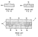
- One of the prior art fuel cells is diagrammatically illustrated in Fig. 11 and designated as 14, whereas respective fuel cells incorporating features of the various embodiments of the present invention are diagrammatically illustrated in Figs. 27, 28 and 39 and identified by reference numerals to be designated later in the description of those embodiments.
- the fuel cell stack module 10 also includes an electrolyte reservoir 16, a distribution block 18, and a pump 20 for supplying electrolyte from the reservoir 16 via a primary supply line 22 to the distribution block 18.
- the fuel cell stacks 12 are connected individually in flow communication with the electrolyte distribution block 18 and reservoir 16 by respective stack supply lines 24 and return or drain lines 26.
- the distribution block 18 includes an electrolyte chamber (not shown) for each stack 12 in the module 10 and a single overflow chamber (not shown).
- the stack supply lines 24 interconnect electrolyte fill holes (not shown in Fig.
- a predetermined electrolyte volume is forced by the pump 20 through the primary supply line 22 to the distribution block 18.
- an equal amount of electrolyte is delivered to each electrolyte chamber.
- Excess electrolyte flows into the overflow chamber and is returned to the reservoir 16 through the overflow return line 28.
- Electrolyte from the chambers is delivered through the stack supply lines 24 to the fill holes in the tops of the respective stacks 12.
- electrolyte is delivered in predetermined periodic pulses of short duration by the pump 20 rather than by continuous flow.
- Gravitational force assists circulation of electrolyte through the fill holes and the internal supply system (both, the prior art embodiment in Fig. 2 and the various embodiments of the improved system of the present invention in Figs. 12 and 29 to be described below) of the fuel cell stacks.
- Any electrolyte not absorbed passes out of the stacks 12 through the drain holes (not shown in Fig. 1) and is returned to the reservoir 16 through the drain lines 26.
- each fuel stack 12 of the module 10 includes a multiplicity of repeating fuel cells, such as designated 14 in the case of the prior art illustrated in Fig. 11, being arranged such that each cell is electrically connected in series with one another in a conventional manner (not shown).
- Each fuel cell whether the prior art one 14 of Fig. 11 which will now be described or any of the fuel cells (whose reference numerals will be identified later) of Figs. 27, 28 and 39 associated with the various embodiments of the present invention, shares the same basic components.
- each fuel cell for example cell 14 in Fig. 11, includes top and bottom bipolar plates 30 between which are sandwiched a lower anode electrode 32, an electrolyte-containing porous matrix 34 and an upper cathode electrode 36.
- shims or gaskets 38 are ordinarily provided for sealing about the peripheries of the electrodes.
- each bipolar plate 30 is composed of a relatively thick rigid material such as a compression molded graphite resin composite while each electrode 32, 36 is a thin sheet of a porous graphite material provided with a porous graphite fiber backing for added structural integrity.
- the matrix 34 is composed of thin tissue-like sheets made of porous graphite saturatable with an electrolytic acid, such as concentrated phosphoric acid. Many other materials and structures can also be used to compose the components of the fuel cell 14.
- a full fuel cell stack typically includes end plates 40 in the form of half-bipolar plates, with a top half-bipolar plate 40 serving as the upper end plate and a bottom half-bipolar plate 40 serving as the lower end plate.
- the stack 12 is held together top and bottom compression plates 42 which contain the aforementioned electrolyte fill and drain holes, designated 44 and 46 in Fig. 2.
- the bipolar plates 30 are typically provided on opposite sides with a set of process channels (not seen) including fuel channels on one side and oxidant channels on the other side.
- a fuel such as hydrogen, organics or metals
- an oxidant such as a halogen, air or other oxygen-containing material
- Fuel inlet and outlet manifolds (not shown) and oxidant inlet and outlet manifolds (not shown) are typically attached to respective inlet and outlet regions of the fuel cell stacks 12 in communication with the fuel and oxidant channels to provide fuel and oxidant flows to and from the stack.
- Electrical power and heat are generated by the interaction of the fuel and oxidant through the electrodes 32, 36 and electrolyte matrix 34.
- An exemplary fuel cell 14 utilizes hydrogen fuel, air as the oxidant and phosphoric acid as the electrolyte.
- each of the stacks 12 ordinarily includes cooling modules composed of a pair of plates 48, as seen in Fig. 2.
- the cooling modules are placed between the fuel cells 14 at selected positions within the stack 12.
- a cooling module may, for example, be placed at approximately seventy evenly spaced locations in the stack 12.
- Each module is preferably comprised of a material similar to that of the bipolar plates 30 and has air cooling passages (not shown) therethrough.
- typical bipolar plates 30A and 30B (being identical but one rotated 180 degrees about a vertical axis with respect to the other when assembled in the stack) separate the fuel cells 14 (one cell being shown in Fig. 11) and are arranged in alternating fashion throughout the stack 12.
- Each plate 30 has single electrolyte flow grooves 50 (see also Fig. 9) defined on its upper anode-supporting side along opposite longitudinal edges thereof.
- electrolyte flow passages 52 extend through the plates 30 in communicative relation with corresponding ones of a pair of opposite ends of the grooves.
- each upper cooling plate 48A of the stack 12 has similar grooves 54 and passages 56 aligned with the passages 56 of the next upper plate 30 as shown in Fig. 2.
- Each lower cooling plate 48B only has the passages 56, as shown in Figs. 2, 7 and 8, aligned with the passages 56 of the upper cooling plate 48A and with the grooves 50 of the next lower plate 30.
- electrolyte flows through the cells 14 of the stack 12 along the serpentine path defined by the flow grooves 50, 54 and passages 52, 56 of the respective plates 30, 48.
- electrolyte since there is only the single path by which the electrolyte can pass through the stack 12 for supplying electrolyte to all of the cells therein, it will be readily appreciated that if an obstruction should develop in one of the grooves, for instance due to the matrix 34 (Fig. 11) sagging into one of the grooves over time, the electrolyte will not reach those cells beyond or below the location of the blockage. Further, those cells above the blockage will become flooded once the head pressure of the electrolyte rises sufficiently. It is such problems that the embodiments of the improved internal electrolyte supply system of the present invention, which will now be described, are particularly suited to alleviate.
- the stack 164 is composed of a multiplicity of repeating fuel cells 166, two of which are partially seen in Figs. 27 and 28.
- the fuel cell 166 includes top and bottom bipolar plates 168 between which are sandwiched a lower anode electrode 170, an electrolyte containing porous matrix 172 and an upper cathode electrode 174.
- a gasket 176 is ordinarily provided for sealing about the peripheries of the electrodes.
- the internal electrolyte supply system in the stack 164 interconnects the pairs of fill holes 178 in opposite end portions of the top compression plate 180 and the pairs of drain holes 182 in the opposite end portions of the bottom compression plate 180 of the stack.
- the first embodiment of the supply system routes electrolyte through the fuel cell stack 164 along a series of first paths each extending horizontally and directly through one of the fuel cells between the bipolar plates 168 thereof so as to expose electrolyte to the matrix 172 and along a series of second paths extending vertically through the stack 164 adjacent to opposite ends of the first horizontal paths.
- the second paths are in communicative flow relation to the first paths and adapted to supply electrolyte directly to the respective first paths.
- the bipolar plates 168A, 168B of the stack 164 of Fig. 12 include two pairs of dual electrolyte flow grooves 184, 186 the auxiliary grooves being located outboard in Figs. 13 and 14.
- the auxiliary grooves 186 extend generally parallel to and are interconnected with the primary grooves 184 by a series of spaced apart cross flow channels 188 (see also Figs. 15-17 and 22-24) defined in the plates 168A, 168B by intermittent walls 190 so as to provide the communicative flow relation therebetween.
- primary grooves 184 are covered by the gasket 176, as seen in Figs. 27 and 28.
- an electrolyte transport wick 192 is disposed in the auxiliary grooves 186 of each cell (although only one wick is depicted in Fig. 13) and is engaged with and supports the matrix 172 thereof for facilitating transfer of electrolyte to the matrix 172.
- the bipolar plates 168A, 168B of the stack 164 include means defined therein which supply electrolyte downwardly through the stack in a by-pass fashion and to the primary grooves 184 so as to produce a cascading electrolyte flow.
- Such means include electrolyte flow passages 194 longitudinally aligned and spaced outwardly from the opposite ends of the auxiliary grooves 186 and extending through the plates 168A, 168B of the cells in spaced communicative flow relation with the opposite ends of the primary grooves 184, and a dam or step 196 defined in the plates between the respective electrolyte flow passage 194 and primary groove 184.
- the steps 196 (see also Figs. 18-19 and 25-26) establish the communicative flow relation and produces the cascading electrolyte flow between the passages 194 and primary grooves 184.
- upper cooling plates 195 have the passages 194 in their left end portions and the groove 184, passages 194 and steps 196 in their right end portions, whereas lower cooling plates 197 have only passages 194 in their left and right end portions.
- the offset or displacement of the passages 194 from primary grooves 184 via the steps 196 provides a by-pass type arrangement and causes small pools of electrolyte to form in the grooves 184, 186 at every bipolar plate 168 which overflow to the next lower plate. In this arrangement, no head pressure exists in the flow of electrolyte.
- a fuel cell stack 198 is composed of a multiplicity of repeating fuel cells 200, one of which is partially seen in Fig. 39.
- the fuel cell 200 includes top and bottom bipolar plates 202 between which are sandwiched a lower anode electrode 204, an electrolyte-containing porous matrix 206 and an upper cathode electrode 208.
- a gasket 210 is ordinarily provided for sealing about the peripheries of the electrodes.
- the internal electrolyte supply system in the stack 198 interconnects the pairs of fill holes 212 in opposite end portions of the top compression plate 214 and the pairs of drain holes 216 in the opposite end portions of the bottom compression plate 214 of the stack.
- the second embodiment of the supply system being similar to the first embodiment, routes electrolyte through the fuel cell stack 198 along a series of first paths each extending horizontally and directly through one of the fuel cells between the bipolar plates 202 thereof so as to expose electrolyte to the matrix 206 and along a series of second paths extending vertically through the stack 198 adjacent to opposite ends of the first horizontal paths.
- the second paths are in communicative flow relation to the first paths and adapted to supply electrolyte directly to the respective first paths.
- the supply system also incorporates some modifications of the features found in the first embodiment as will become clearer below.
- the bipolar plates 202A, 202B of the stack 198 of Fig. 29 are identical, with one plate merely being rotated about a longitudinal horizontal axis 180 degrees with respect to the other plate.
- the plates 202A, 202B include single electrolyte flow grooves 218, 220, one (218) being straight and the other (220) offset and aligned with one of the pairs of electrolyte flow passages 222 defined through opposite ends of the plates adjacent opposite ends of the grooves 218, 220. It will be noted that there are no auxiliary grooves here, as in the first embodiment.
- an electrolyte transport wick 224 is disposed in the straight and offset grooves 218, 220 of each cell (although no wicks are shown in Figs. 30 to 33, they are shown in Figs. 34, 35, 38 and 39) and is engaged with and supports the matrix 206 thereof for facilitating transfer of electrolyte to the matrix.
- bipolar plates 202A, 202B of the second embodiment employ single grooves 218, 220, they still have means defined therein, as in the first embodiment, which supply electrolyte downwardly through the stack in a by-pass fashion and to the straight and offset grooves 218, 220 so as to produce a cascading electrolyte flow.
- Such means includes the above-mentioned electrolyte flow passages 222 transversely aligned and spaced laterally from the opposite ends of the grooves 218, 220, and a dam or step 226 defined in the plates between the respective electrolyte flow passage 194 and opposite ends of the grooves 218, 220.
- the steps 226 (see also Figs. 34-39) establish a communicative flow relation and produce the cascading electrolyte flow between the passages 222 and the grooves 218, 220.
- upper cooling plates 228 have one or the other of the grooves 218, 220 and have the passages 222 and steps 226 in their left and right end portions, whereas lower cooling plates 230 have only passages 222 in their left and right end portions.
Claims (11)
- Batterie (164; 198) de piles à combustible comportant des moyens d'amenée et d'évacuation d'électrolyte et une pluralité de piles à combustible (166; 200) empilées les unes sur les autres, chaque pile à combustible comprenant des plaques bipolaires (168; 202) qui la séparent des piles à combustibles adjacentes dans la batterie de celles-ci, une matrice (172; 206) contenant un électrolyte et disposée entre ces plaques, et un système interne d'alimentation en électrolyte reliant mutuellement les moyens d'amenée et d'évacuation précités, caractérisée en ce que le système susvisé comprend:(a) des premiers moyens formés de façon répétée dans toute la batterie de piles à combustible pour l'écoulement de l'électrolyte le long d'une série de premiers circuits (184; 186; 218; 220) s'étendant chacun horizontalement et directement à travers une des piles (166; 200) de la batterie (164; 198), entre les plaques (168; 202) de cette dernière, de manière à mettre l'électrolyte en contact avec la matrice (172; 206) de la pile;(b) des seconds moyens formés de façon répétée dans toute la batterie (164; 198) de piles à combustible pour l'écoulement de l'électrolyte le long d'une série de seconds circuits (194; 222) s'étendant à travers les plaques (168; 202) de la batterie (164; 198) de piles à combustible, aux extrémités opposées des premiers circuits horizontaux (184, 186; 218, 220), et formant des retenues d'électrolyte à l'aide de barrages ou ressauts (196; 226) et des circuits (184, 186; 218, 220), les seconds circuits (194; 226) étant en communication d'écoulement avec les premiers circuits (184, 186; 218, 220) et étant adaptés pour alimenter en électrolyte, à la façon d'une dérivation, directement les premiers circuits respectifs (184, 186; 218, 220); et(c) des troisièmes moyens (194, 196; 222, 226) formés dans les plaques (168; 202), entre les premiers moyens et seconds moyens qui établissent la communication d'écoulement en dérivation, et produisant entre ces moyens un écoulement en cascade.
- Batterie (164; 198) de piles à combustible selon la revendication 1, caractérisée en ce que les premiers moyens comprennent au moins une rainure (184, 186; 218, 220) d'écoulement d'électrolyte formée dans une des faces d'une des plaques (168A, 168B; 202A, 202B) de chaque pile pour l'écoulement de l'électrolyte le long du premier circuit à travers chaque pile (166;198).
- Batterie de piles à combustible selon la revendication 2, caractérisée en ce qu'une mèche (192; 224) de transport d'électrolyte est disposée dans une rainure (186; 218, 220) de chaque pile et est en contact avec la matrice (172; 206) de chaque pile (166; 198) pour faciliter le transfert de l'électrolyte jusqu'à la matrice (172; 206).
- Batterie de piles à combustible selon la revendication 2 ou 3, caractérisée en ce que les seconds moyens comprennent un passage (194; 226) d'écoulement d'électrolyte s'étendant à travers les plaques (168A, 168B; 202A, 202B) des piles (166; 200) en communication d'écoulement avec chaque extrémité opposée d'une des rainures (184, 186; 218, 220) d'écoulement d'électrolyte qui y sont formées.
- Batterie de piles à combustible selon la revendication 4, caractérisée en ce que les troisièmes moyens comprennent un ressaut (196; 226) formé dans chacune des plaques (168A, 168B; 202A, 202B), entre le passage (194; 226) d'écoulement d'électrolyte et la rainure (184, 186; 218, 220) qui établit la communication d'écoulement précitée, et produisent l'écoulement en cascade de l'électrolyte entre ce passage et cette rainure.
- Batterie de piles à combustible selon la revendication 1, caractérisée en ce que les premiers moyens comprennent au moins une paire de rainures (184, 186) d'écoulement d'électrolyte formées en communication mutuelle d'écoulement, côte à côte, dans une des faces d'une des plaques de chaque pile pour l'écoulement de l'électrolyte le long du premier circuit à travers la pile.
- Batterie de piles à combustible selon la revendication 6, caractérisée en ce qu'au moins un canal transversal (188) est formé dans la face précitée de la plaque précitée (168) de chaque pile (166), entre la paire de rainures (184, 186) d'écoulement d'électrolyte, et relie mutuellement ces rainures de manière à assurer entre elles la communication mutuelle d'écoulement.
- Batterie de piles à combustible selon la revendication 6, caractérisée en ce qu'une série de canaux transversaux (188) espacés l'un de l'autre sont formés dans la première face précitée de ladite première plaque (168) de chaque pile, entre la paire de rainures (18, 186) d'écoulement d'électrolyte, et relient mutuellement ces rainures de manière à assurer entre elles la communication mutuelle d'écoulement.
- Batterie de piles à combustible selon la revendication 6, caractérisée en ce qu'une mèche (192) de transport d'électrolyte est disposée dans une (186) des rainures de chaque pile (166) et est en contact avec la matrice (172) de la pile (166) pour faciliter le transport de l'électrolyte jusqu'à la matrice.
- Batterie de piles à combustible selon la revendication 9, caractérisée en ce que les seconds moyens comprennent un passage (188) d'écoulement d'électrolyte s'étendant à travers les plaques des piles en communication mutuelle d'écoulement avec chaque extrémité opposée de l'autre (186) des rainures (184, 186) d'écoulement d'électrolyte qui y est formée et qui ne contient pas la mèche (192).
- Batterie de piles à combustible selon la revendication 6, caractérisée en ce que les troisièmes moyens comprennent un ressaut (196) formé dans chacune des plaques (168A, 168B), entre le passage correspondant (194) d'écoulement d'électrolyte et l'autre (184) des rainures qui établit une communication d'écoulement, et produisent l'écoulement en cascade précité de l'électrolyte entre ce passage et cette rainure.
Applications Claiming Priority (2)
| Application Number | Priority Date | Filing Date | Title |
|---|---|---|---|
| US06/940,320 US4732822A (en) | 1986-12-10 | 1986-12-10 | Internal electrolyte supply system for reliable transport throughout fuel cell stacks |
| US940320 | 2001-08-27 |
Publications (3)
| Publication Number | Publication Date |
|---|---|
| EP0274003A2 EP0274003A2 (fr) | 1988-07-13 |
| EP0274003A3 EP0274003A3 (en) | 1989-03-08 |
| EP0274003B1 true EP0274003B1 (fr) | 1992-10-14 |
Family
ID=25474626
Family Applications (1)
| Application Number | Title | Priority Date | Filing Date |
|---|---|---|---|
| EP87111437A Expired - Lifetime EP0274003B1 (fr) | 1986-12-10 | 1987-08-07 | Système d'admission interne d'électrolyte pour le transport fiable à travers une batterie de cellules à combustible |
Country Status (6)
| Country | Link |
|---|---|
| US (1) | US4732822A (fr) |
| EP (1) | EP0274003B1 (fr) |
| JP (1) | JPS63155562A (fr) |
| CA (1) | CA1285316C (fr) |
| DE (1) | DE3782234T2 (fr) |
| ZA (1) | ZA875933B (fr) |
Families Citing this family (34)
| Publication number | Priority date | Publication date | Assignee | Title |
|---|---|---|---|---|
| IT1237140B (it) * | 1988-11-28 | 1993-05-24 | Toshiba Kk | Cella a combustibile |
| JP2501169B2 (ja) * | 1993-03-18 | 1996-05-29 | 株式会社日立製作所 | 燃料電池及び電解質補給容器及び電解質補給方法 |
| US5376472A (en) * | 1993-10-06 | 1994-12-27 | Ceramatec, Inc. | Semi-internally manifolded interconnect |
| US5480738A (en) * | 1994-02-04 | 1996-01-02 | Ceramatec, Inc. | Fuel cell module |
| US5763114A (en) * | 1994-09-01 | 1998-06-09 | Gas Research Institute | Integrated reformer/CPN SOFC stack module design |
| US5612149A (en) * | 1996-01-02 | 1997-03-18 | Ceramatec, Inc. | Fuel cell column heat exchanger mated module |
| JP3580455B2 (ja) * | 1996-03-25 | 2004-10-20 | 石川島播磨重工業株式会社 | 溶融炭酸塩型燃料電池とこれを用いた発電装置 |
| US7682714B2 (en) * | 2001-05-25 | 2010-03-23 | Toyota Jidosha Kabushiki Kaisha | Connecting structure of a cell monitor connector to a fuel cell stack |
| US20040001991A1 (en) * | 2002-07-01 | 2004-01-01 | Kinkelaar Mark R. | Capillarity structures for water and/or fuel management in fuel cells |
| DE60304894T2 (de) * | 2002-11-18 | 2007-01-18 | GenCell Corp., Southbury | Bipolarplatte mit zwei-durchgängen-anode |
| WO2005082024A2 (fr) * | 2004-02-24 | 2005-09-09 | Ini Power Systems, Inc. | Pile a combustible et procede de fabrication correspondant |
| US7531264B2 (en) * | 2004-06-07 | 2009-05-12 | Hyteon Inc. | Fuel cell stack with even distributing gas manifolds |
| US7524575B2 (en) * | 2004-06-07 | 2009-04-28 | Hyteon Inc. | Flow field plate for use in fuel cells |
| US20060008695A1 (en) * | 2004-07-09 | 2006-01-12 | Dingrong Bai | Fuel cell with in-cell humidification |
| JP2008513962A (ja) * | 2004-09-15 | 2008-05-01 | アイエヌアイ パワー システムズ インコーポレイテッド | 電気化学電池 |
| US7314680B2 (en) * | 2004-09-24 | 2008-01-01 | Hyteon Inc | Integrated fuel cell power module |
| US7479333B2 (en) * | 2004-12-13 | 2009-01-20 | Hyteon, Inc. | Fuel cell stack with multiple groups of cells and flow passes |
| US20060188763A1 (en) * | 2005-02-22 | 2006-08-24 | Dingrong Bai | Fuel cell system comprising modular design features |
| US8158300B2 (en) * | 2006-09-19 | 2012-04-17 | Ini Power Systems, Inc. | Permselective composite membrane for electrochemical cells |
| US7985505B2 (en) * | 2006-12-15 | 2011-07-26 | General Electric Company | Fuel cell apparatus and associated method |
| US20080145723A1 (en) * | 2006-12-15 | 2008-06-19 | General Electric Company | Rechargeable fuel cell and method |
| US8343687B2 (en) * | 2006-12-19 | 2013-01-01 | General Electric Company | Rechargeable fuel cell system |
| WO2008122042A1 (fr) * | 2007-04-02 | 2008-10-09 | Ini Power Systems, Inc. | Piles à combustible microfluidiques |
| US8551667B2 (en) * | 2007-04-17 | 2013-10-08 | Ini Power Systems, Inc. | Hydrogel barrier for fuel cells |
| US20090035644A1 (en) * | 2007-07-31 | 2009-02-05 | Markoski Larry J | Microfluidic Fuel Cell Electrode System |
| WO2009017150A1 (fr) * | 2007-08-02 | 2009-02-05 | Sony Corporation | Système d'empilement de piles à combustible, structure de canal, pile à combustible, électrode et dispositif électronique |
| US8163429B2 (en) * | 2009-02-05 | 2012-04-24 | Ini Power Systems, Inc. | High efficiency fuel cell system |
| JP4916536B2 (ja) * | 2009-08-06 | 2012-04-11 | 日立オムロンターミナルソリューションズ株式会社 | Icカード処理装置 |
| US8783304B2 (en) | 2010-12-03 | 2014-07-22 | Ini Power Systems, Inc. | Liquid containers and apparatus for use with power producing devices |
| US9065095B2 (en) | 2011-01-05 | 2015-06-23 | Ini Power Systems, Inc. | Method and apparatus for enhancing power density of direct liquid fuel cells |
| GB2515994A (en) * | 2013-04-08 | 2015-01-14 | Acal Energy Ltd | Fuel cells |
| JP2018073715A (ja) * | 2016-11-02 | 2018-05-10 | マグネクス株式会社 | 燃料電池エンドプレート |
| KR102602415B1 (ko) * | 2018-09-04 | 2023-11-14 | 현대자동차주식회사 | 전극막접합체 |
| US11444298B2 (en) | 2019-07-18 | 2022-09-13 | Hyaxiom, Inc. | Electrolyte shunt migration management in a fuel cell stack |
Family Cites Families (30)
| Publication number | Priority date | Publication date | Assignee | Title |
|---|---|---|---|---|
| US3239384A (en) * | 1963-01-23 | 1966-03-08 | Corson G & W H | Liquid ammonia deferred action electric-current producing cell |
| DE1496330C3 (de) * | 1965-06-16 | 1975-10-02 | Varta Batterie Ag, 3000 Hannover | Druckgasbetätigte, belastungsabhängige Pumpe zur Umwälzung von Gasen und Flüssigkeiten in Brennstoffelementen |
| FR2287784A1 (fr) * | 1974-10-09 | 1976-05-07 | Inst Francais Du Petrole | Pile a combustible perfectionnee |
| FR2302600A1 (fr) * | 1975-02-25 | 1976-09-24 | Inst Francais Du Petrole | Nouveau perfectionnement aux piles a combustible |
| BE868387A (nl) * | 1977-06-29 | 1978-12-27 | Electrochem Energieconversie | Batterij-eenheid, bevattende een of meer brandstofcellenblokken |
| US4168349A (en) * | 1978-04-27 | 1979-09-18 | Westinghouse Electric Corp. | Iron/air battery system having circulating electrolyte and a horizontal cell configuration |
| FR2442517A1 (fr) * | 1978-11-24 | 1980-06-20 | Inst Francais Du Petrole | Methode et dispositif pour alimenter une pile a combustible en produits reactifs |
| US4324844A (en) * | 1980-04-28 | 1982-04-13 | Westinghouse Electric Corp. | Variable area fuel cell cooling |
| US4276355A (en) * | 1980-04-28 | 1981-06-30 | Westinghouse Electric Corp. | Fuel cell system configurations |
| US4292379A (en) * | 1980-04-28 | 1981-09-29 | Westinghouse Electric Corp. | Variable area fuel cell process channels |
| JPS5755071A (en) * | 1980-09-20 | 1982-04-01 | Hitachi Ltd | Fuel cell laminate |
| US4414291A (en) * | 1980-12-24 | 1983-11-08 | United Technologies Corporation | Method for reducing electrolyte loss from an electrochemical cell |
| US4342816A (en) * | 1981-04-22 | 1982-08-03 | The United States Of America As Represented By The United States Department Of Energy | Fuel cell stack arrangements |
| JPS5823166A (ja) * | 1981-08-04 | 1983-02-10 | Mitsubishi Electric Corp | 燃料電池 |
| JPS5842179A (ja) * | 1981-09-08 | 1983-03-11 | Hitachi Ltd | 燃料電池 |
| US4366211A (en) * | 1981-09-21 | 1982-12-28 | Westinghouse Electric Corp. | Control of electrolyte fill to fuel cell stack |
| US4383009A (en) * | 1981-09-21 | 1983-05-10 | The United States Of America As Represented By The United States Department Of Energy | Low hydrostatic head electrolyte addition to fuel cell stacks |
| JPS58103784A (ja) * | 1981-12-16 | 1983-06-20 | Hitachi Ltd | 燃料電池 |
| JPS58164151A (ja) * | 1982-03-25 | 1983-09-29 | Kansai Electric Power Co Inc:The | マトリツクス型燃料電池の電解質補給装置 |
| US4467019A (en) * | 1982-09-30 | 1984-08-21 | Engelhard Corporation | Fuel cell with electrolyte feed system |
| US4463067A (en) * | 1982-09-30 | 1984-07-31 | Engelhard Corporation | Fuel cell and system for supplying electrolyte thereto utilizing cascade feed |
| US4463066A (en) * | 1982-09-30 | 1984-07-31 | Engelhard Corporation | Fuel cell and system for supplying electrolyte thereto |
| US4463068A (en) * | 1982-09-30 | 1984-07-31 | Engelhard Corporation | Fuel cell and system for supplying electrolyte thereto with wick feed |
| JPS59151771A (ja) * | 1983-02-16 | 1984-08-30 | Sanyo Electric Co Ltd | 燃料電池の電解液補給装置 |
| US4481266A (en) * | 1983-03-25 | 1984-11-06 | Littauer Ernest L | Reactive metal battery having continuous supply of cathode reactant |
| JPS59217958A (ja) * | 1983-05-25 | 1984-12-08 | Fuji Electric Corp Res & Dev Ltd | マトリツクス型燃料電池の電解質補給装置 |
| JPS60150560A (ja) * | 1984-01-18 | 1985-08-08 | Fuji Electric Corp Res & Dev Ltd | マトリツクス形燃料電池の電解質補給装置 |
| JPS60198059A (ja) * | 1984-03-21 | 1985-10-07 | Fuji Electric Corp Res & Dev Ltd | マトリツクス形燃料電池の電解質補給構造 |
| JPH0630253B2 (ja) * | 1985-03-22 | 1994-04-20 | 株式会社日立製作所 | 燃料電池 |
| US4572876A (en) * | 1985-04-01 | 1986-02-25 | Westinghouse Electric Corp. | Apparatus for supplying electrolyte to fuel cell stacks |
-
1986
- 1986-12-10 US US06/940,320 patent/US4732822A/en not_active Expired - Lifetime
-
1987
- 1987-08-07 EP EP87111437A patent/EP0274003B1/fr not_active Expired - Lifetime
- 1987-08-07 DE DE8787111437T patent/DE3782234T2/de not_active Expired - Fee Related
- 1987-08-11 ZA ZA875933A patent/ZA875933B/xx unknown
- 1987-09-08 JP JP62225107A patent/JPS63155562A/ja active Pending
- 1987-12-08 CA CA000553834A patent/CA1285316C/fr not_active Expired - Lifetime
Also Published As
| Publication number | Publication date |
|---|---|
| US4732822A (en) | 1988-03-22 |
| JPS63155562A (ja) | 1988-06-28 |
| DE3782234T2 (de) | 1993-04-15 |
| ZA875933B (en) | 1988-02-22 |
| DE3782234D1 (de) | 1992-11-19 |
| EP0274003A2 (fr) | 1988-07-13 |
| EP0274003A3 (en) | 1989-03-08 |
| CA1285316C (fr) | 1991-06-25 |
Similar Documents
| Publication | Publication Date | Title |
|---|---|---|
| EP0274003B1 (fr) | Système d'admission interne d'électrolyte pour le transport fiable à travers une batterie de cellules à combustible | |
| US6582844B2 (en) | Method of cooling a fuel cell | |
| EP0521830B1 (fr) | Empilement de piles à combustible entièrement pourvu de canaux intérieurs | |
| US6383347B1 (en) | Electrochemical cell utilizing rigid support members | |
| US5750281A (en) | Edge manifold assembly for an electrochemical fuel cell stack | |
| US6558832B1 (en) | Fuel cell module | |
| US4853301A (en) | Fuel cell plates with skewed process channels for uniform distribution of stack compression load | |
| US4631239A (en) | Fuel cell plates with improved arrangement of process channels for enhanced pressure drop across the plates | |
| JP4081428B2 (ja) | 燃料電池 | |
| JP5227543B2 (ja) | 燃料電池 | |
| JP3553245B2 (ja) | 直接メタノール型燃料電池 | |
| JP2008536258A (ja) | 流れ場極板の配列 | |
| US10680255B2 (en) | Flow-guiding plate for a fuel cell | |
| JP2007134206A (ja) | 燃料電池スタック | |
| JP2001143724A (ja) | 燃料電池 | |
| CA2330946A1 (fr) | Empilage de piles a combustible | |
| KR101119479B1 (ko) | 연료 전지 스택용 양극성 분리기 | |
| US7354674B2 (en) | Electrode structure for stacked alkaline fuel cells | |
| GB2336937A (en) | Stack assembly primarily for an electrochemical cell | |
| JP4109569B2 (ja) | 燃料電池 | |
| EP1646099B1 (fr) | Dispositif électrochimique | |
| CA2435571A1 (fr) | Dispositif electrolytique | |
| US20030170528A1 (en) | Moldable separator plate for electrochemical devices and cells | |
| JP2007234405A (ja) | 燃料電池スタック | |
| CN216958101U (zh) | 一种并联燃料电池电堆 |
Legal Events
| Date | Code | Title | Description |
|---|---|---|---|
| PUAI | Public reference made under article 153(3) epc to a published international application that has entered the european phase |
Free format text: ORIGINAL CODE: 0009012 |
|
| AK | Designated contracting states |
Kind code of ref document: A2 Designated state(s): DE FR GB NL SE |
|
| PUAL | Search report despatched |
Free format text: ORIGINAL CODE: 0009013 |
|
| AK | Designated contracting states |
Kind code of ref document: A3 Designated state(s): DE FR GB NL SE |
|
| 17P | Request for examination filed |
Effective date: 19890321 |
|
| 17Q | First examination report despatched |
Effective date: 19901112 |
|
| GRAA | (expected) grant |
Free format text: ORIGINAL CODE: 0009210 |
|
| AK | Designated contracting states |
Kind code of ref document: B1 Designated state(s): DE FR GB NL SE |
|
| ET | Fr: translation filed | ||
| REF | Corresponds to: |
Ref document number: 3782234 Country of ref document: DE Date of ref document: 19921119 |
|
| PLBE | No opposition filed within time limit |
Free format text: ORIGINAL CODE: 0009261 |
|
| STAA | Information on the status of an ep patent application or granted ep patent |
Free format text: STATUS: NO OPPOSITION FILED WITHIN TIME LIMIT |
|
| REG | Reference to a national code |
Ref country code: FR Ref legal event code: TP |
|
| 26N | No opposition filed | ||
| NLS | Nl: assignments of ep-patents |
Owner name: ENVIRONMENTAL ENERGY SYSTEMS, INC. TE LARGE, PENNS |
|
| EAL | Se: european patent in force in sweden |
Ref document number: 87111437.7 |
|
| PGFP | Annual fee paid to national office [announced via postgrant information from national office to epo] |
Ref country code: FR Payment date: 19980619 Year of fee payment: 12 |
|
| PGFP | Annual fee paid to national office [announced via postgrant information from national office to epo] |
Ref country code: SE Payment date: 19980624 Year of fee payment: 12 Ref country code: GB Payment date: 19980624 Year of fee payment: 12 |
|
| PGFP | Annual fee paid to national office [announced via postgrant information from national office to epo] |
Ref country code: NL Payment date: 19980730 Year of fee payment: 12 |
|
| PGFP | Annual fee paid to national office [announced via postgrant information from national office to epo] |
Ref country code: DE Payment date: 19980930 Year of fee payment: 12 |
|
| PG25 | Lapsed in a contracting state [announced via postgrant information from national office to epo] |
Ref country code: GB Free format text: LAPSE BECAUSE OF NON-PAYMENT OF DUE FEES Effective date: 19990807 |
|
| PG25 | Lapsed in a contracting state [announced via postgrant information from national office to epo] |
Ref country code: SE Free format text: THE PATENT HAS BEEN ANNULLED BY A DECISION OF A NATIONAL AUTHORITY Effective date: 19990830 |
|
| PG25 | Lapsed in a contracting state [announced via postgrant information from national office to epo] |
Ref country code: NL Free format text: LAPSE BECAUSE OF NON-PAYMENT OF DUE FEES Effective date: 20000301 |
|
| GBPC | Gb: european patent ceased through non-payment of renewal fee |
Effective date: 19990807 |
|
| PG25 | Lapsed in a contracting state [announced via postgrant information from national office to epo] |
Ref country code: FR Free format text: LAPSE BECAUSE OF NON-PAYMENT OF DUE FEES Effective date: 20000428 |
|
| EUG | Se: european patent has lapsed |
Ref document number: 87111437.7 |
|
| NLV4 | Nl: lapsed or anulled due to non-payment of the annual fee |
Effective date: 20000301 |
|
| PG25 | Lapsed in a contracting state [announced via postgrant information from national office to epo] |
Ref country code: DE Free format text: LAPSE BECAUSE OF NON-PAYMENT OF DUE FEES Effective date: 20000601 |
|
| REG | Reference to a national code |
Ref country code: FR Ref legal event code: ST |