EP0274003B1 - Improved internal electrolyte supply system for reliable transport throughout fuel cell stack - Google Patents
Improved internal electrolyte supply system for reliable transport throughout fuel cell stack Download PDFInfo
- Publication number
- EP0274003B1 EP0274003B1 EP87111437A EP87111437A EP0274003B1 EP 0274003 B1 EP0274003 B1 EP 0274003B1 EP 87111437 A EP87111437 A EP 87111437A EP 87111437 A EP87111437 A EP 87111437A EP 0274003 B1 EP0274003 B1 EP 0274003B1
- Authority
- EP
- European Patent Office
- Prior art keywords
- electrolyte
- fuel cell
- flow
- plates
- cell stack
- Prior art date
- Legal status (The legal status is an assumption and is not a legal conclusion. Google has not performed a legal analysis and makes no representation as to the accuracy of the status listed.)
- Expired - Lifetime
Links
Images


Classifications
-
- H—ELECTRICITY
- H01—ELECTRIC ELEMENTS
- H01M—PROCESSES OR MEANS, e.g. BATTERIES, FOR THE DIRECT CONVERSION OF CHEMICAL ENERGY INTO ELECTRICAL ENERGY
- H01M8/00—Fuel cells; Manufacture thereof
- H01M8/04—Auxiliary arrangements, e.g. for control of pressure or for circulation of fluids
- H01M8/04276—Arrangements for managing the electrolyte stream, e.g. heat exchange
- H01M8/04283—Supply means of electrolyte to or in matrix-fuel cells
-
- H—ELECTRICITY
- H01—ELECTRIC ELEMENTS
- H01M—PROCESSES OR MEANS, e.g. BATTERIES, FOR THE DIRECT CONVERSION OF CHEMICAL ENERGY INTO ELECTRICAL ENERGY
- H01M8/00—Fuel cells; Manufacture thereof
- H01M8/24—Grouping of fuel cells, e.g. stacking of fuel cells
- H01M8/241—Grouping of fuel cells, e.g. stacking of fuel cells with solid or matrix-supported electrolytes
-
- H—ELECTRICITY
- H01—ELECTRIC ELEMENTS
- H01M—PROCESSES OR MEANS, e.g. BATTERIES, FOR THE DIRECT CONVERSION OF CHEMICAL ENERGY INTO ELECTRICAL ENERGY
- H01M8/00—Fuel cells; Manufacture thereof
- H01M8/24—Grouping of fuel cells, e.g. stacking of fuel cells
- H01M8/2465—Details of groupings of fuel cells
- H01M8/2483—Details of groupings of fuel cells characterised by internal manifolds
-
- H—ELECTRICITY
- H01—ELECTRIC ELEMENTS
- H01M—PROCESSES OR MEANS, e.g. BATTERIES, FOR THE DIRECT CONVERSION OF CHEMICAL ENERGY INTO ELECTRICAL ENERGY
- H01M8/00—Fuel cells; Manufacture thereof
- H01M8/24—Grouping of fuel cells, e.g. stacking of fuel cells
- H01M8/2465—Details of groupings of fuel cells
- H01M8/2484—Details of groupings of fuel cells characterised by external manifolds
-
- Y—GENERAL TAGGING OF NEW TECHNOLOGICAL DEVELOPMENTS; GENERAL TAGGING OF CROSS-SECTIONAL TECHNOLOGIES SPANNING OVER SEVERAL SECTIONS OF THE IPC; TECHNICAL SUBJECTS COVERED BY FORMER USPC CROSS-REFERENCE ART COLLECTIONS [XRACs] AND DIGESTS
- Y02—TECHNOLOGIES OR APPLICATIONS FOR MITIGATION OR ADAPTATION AGAINST CLIMATE CHANGE
- Y02E—REDUCTION OF GREENHOUSE GAS [GHG] EMISSIONS, RELATED TO ENERGY GENERATION, TRANSMISSION OR DISTRIBUTION
- Y02E60/00—Enabling technologies; Technologies with a potential or indirect contribution to GHG emissions mitigation
- Y02E60/30—Hydrogen technology
- Y02E60/50—Fuel cells
Definitions
- This invention relates generally to a stack of fuel cells which convert the latent chemical energy of a fuel into electricity directly and, more particularly, is concerned with an internal electrolyte supply system for reliable transport of electrolyte throughout the fuel cell stack.
- One common fuel cell system includes a plurality of sub-assemblies which except for the top and bottom sub-assemblies, each include two bipolar plates between which is supported two gas electrodes, one an anode and the other a cathode, and a matrix with an ion-conductive electrolyte, such as phosphoric acid, between the anode and cathode electrodes.
- the sub-assemblies herein referred to as fuel cells, are oriented one atop another and electrically connected in series (alternate electron and ion paths) to form a fuel cell stack.
- the top end plate of the top sub-assembly and the bottom end plate of the bottom sub-assembly are each half-bipolar plates.
- Process gases such as a fuel and an oxidant are supplied respectively to the anode and cathode electrodes via manifolds attached to the stack and channels defined in the bipolar plates.
- the fuel in the form of hydrogen atoms when supplied to the anode electrode dissociates into hydrogen ions and electrons.
- the electrons are transmitted from the anode electrode of a given cell across one bipolar plate to the cathode electrode of an adjacent cell, while the hydrogen ions migrate directly through the acidic electrolyte to the cathode electrode of the given cell, where they react with electrons transmitted to the cathode electrode across the other bipolar plate from the anode electrode of the other adjacent cell and with oxygen to form water. This is repeated at and between the cells throughout the stack with electrons then transferring from the last cathode electrode at one end of the stack to the last anode electrode at the other end of the stack in the form of an electrical current through an external circuit where useful work is produced.
- the above-described phosphoric acid fuel cell stack for generating electric power is made up of hundreds of stacked plates, a majority being bipolar plates and a minority being cooling plates, which form a column approximately eight feet in height.
- Each anode electrode is located on the top side of a bipolar plate facing upward, whereas each cathode electrode is located on the bottom side thereof facing downward.
- Electrolyte is supplied to the fuel cells in the stack through fill holes at the top of the stack.
- Most of the plates have electrolyte flow grooves defined on the top surface along a pair of the opposite edges of the plate. These grooves are located below the matrix which is positioned between the electrodes of the cell and distribute the electrolyte across the cell.
- the plates have vertical holes defined therethrough at selected ends of the grooves such that the grooves and holes form a pair of internal independent serpentine feed paths of electrolyte flow from the top fill holes downward through the fuel cell stack.
- Similar internal electrolyte supply systems with single serpentine feed path configurations are disclosed in above-cited U.S. Patent 4,383,009 and first application cross-referenced above, although in these systems the grooves are located such that the electrolyte flow path is above the matrix.
- the present invention resides in a fuel cell stack having electrolyte feed and drain means and a plurality of stacked fuel cells, each fuel cell including bipolar plates separating said fuel cell from adjacent fuel cells in said stack thereof and an electrolyte-containing matrix disposed between said plates, and an internal electrolyte supply system interconnecting said feed and drain means, characterized in that said system comprises: (a) first means defined repeatedly throughout the fuel cell stack for flowing electrolyte along a series of first paths each extending horizontally and directly through at least one of the cells in the stack between the plates thereof so as to expose the electrolyte to the matrix of the cell; (b) second means defined repeatedly throughout the fuel cell stack for flowing electrolyte along a series of second paths extending through the plates of the cell stack at opposite ends of the first horizontal paths and forming pools of electrolyte by means of dams or steps and the paths, the second paths being in communicative flow relation to the first paths and adapted to supply electrolyte in by-pass fashion directly to the respective first paths; and
- the first means includes at least one electrolyte flow groove defined in one side of one of the plates of each cell of the stack.
- an electrolyte transport wick is disposed in the groove and engaged with the matrix of the respective cell for facilitating transfer of electrolyte to the matrix.
- the second means includes an electrolyte flow passage extending through each plate of the respective cells in spaced relation to the electrolyte flow groove defined therein.
- the electrolyte flow passage is in communicative flow relation to the electrolyte flow groove.
- a step is defined in the plate between the electrolyte flow passage and groove which establishes the by-pass communicative flow relation and produces said cascading electrolyte flow therebetween.
- the first means includes at least a pair of electrolyte flow grooves defined in side-by-side communicative flow relation in one side of one of the plates of each cell of the stack. At least one and preferably a series of spaced apart cross channels are defined in the one side of the one cell plate between and interconnecting the pair of electrolyte flow grooves so as to provide the communicative flow relation therebetween. Also, the electrolyte transport wick is disposed in one of the grooves and the electrolyte flow passage of the second means extends through the respective cell plate in spaced relation to the electrolyte flow grooves defined therein.
- the internal electrolyte supply system used in the present invention is much less complex and costly than an external system and more reliable than the prior internal single pass system. All of the embodiments of the electrolyte supply system of the present invention satisfy the basic requirements that: (1) electrolyte be fed internally to the fuel cells in the stack; (2) multiple accesses be provided to the electrolyte grooves along the stack height; and (3) head pressure developed in the electrolyte be limited. While all of the embodiments are adapted for working together to facilitate reliable transport of electrolyte through a common fuel cell stack, some of the embodiments can be provided separately from others in different fuel cell stacks.
- an electrochemical fuel cell stack module which includes a plurality of fuel cell stacks 12.
- Each fuel cell stack 12 contains a multiplicity of repeating fuel cells.
- One of the prior art fuel cells is diagrammatically illustrated in Fig. 11 and designated as 14, whereas respective fuel cells incorporating features of the various embodiments of the present invention are diagrammatically illustrated in Figs. 27, 28 and 39 and identified by reference numerals to be designated later in the description of those embodiments.
- the fuel cell stack module 10 also includes an electrolyte reservoir 16, a distribution block 18, and a pump 20 for supplying electrolyte from the reservoir 16 via a primary supply line 22 to the distribution block 18.
- the fuel cell stacks 12 are connected individually in flow communication with the electrolyte distribution block 18 and reservoir 16 by respective stack supply lines 24 and return or drain lines 26.
- the distribution block 18 includes an electrolyte chamber (not shown) for each stack 12 in the module 10 and a single overflow chamber (not shown).
- the stack supply lines 24 interconnect electrolyte fill holes (not shown in Fig.
- a predetermined electrolyte volume is forced by the pump 20 through the primary supply line 22 to the distribution block 18.
- an equal amount of electrolyte is delivered to each electrolyte chamber.
- Excess electrolyte flows into the overflow chamber and is returned to the reservoir 16 through the overflow return line 28.
- Electrolyte from the chambers is delivered through the stack supply lines 24 to the fill holes in the tops of the respective stacks 12.
- electrolyte is delivered in predetermined periodic pulses of short duration by the pump 20 rather than by continuous flow.
- Gravitational force assists circulation of electrolyte through the fill holes and the internal supply system (both, the prior art embodiment in Fig. 2 and the various embodiments of the improved system of the present invention in Figs. 12 and 29 to be described below) of the fuel cell stacks.
- Any electrolyte not absorbed passes out of the stacks 12 through the drain holes (not shown in Fig. 1) and is returned to the reservoir 16 through the drain lines 26.
- each fuel stack 12 of the module 10 includes a multiplicity of repeating fuel cells, such as designated 14 in the case of the prior art illustrated in Fig. 11, being arranged such that each cell is electrically connected in series with one another in a conventional manner (not shown).
- Each fuel cell whether the prior art one 14 of Fig. 11 which will now be described or any of the fuel cells (whose reference numerals will be identified later) of Figs. 27, 28 and 39 associated with the various embodiments of the present invention, shares the same basic components.
- each fuel cell for example cell 14 in Fig. 11, includes top and bottom bipolar plates 30 between which are sandwiched a lower anode electrode 32, an electrolyte-containing porous matrix 34 and an upper cathode electrode 36.
- shims or gaskets 38 are ordinarily provided for sealing about the peripheries of the electrodes.
- each bipolar plate 30 is composed of a relatively thick rigid material such as a compression molded graphite resin composite while each electrode 32, 36 is a thin sheet of a porous graphite material provided with a porous graphite fiber backing for added structural integrity.
- the matrix 34 is composed of thin tissue-like sheets made of porous graphite saturatable with an electrolytic acid, such as concentrated phosphoric acid. Many other materials and structures can also be used to compose the components of the fuel cell 14.
- a full fuel cell stack typically includes end plates 40 in the form of half-bipolar plates, with a top half-bipolar plate 40 serving as the upper end plate and a bottom half-bipolar plate 40 serving as the lower end plate.
- the stack 12 is held together top and bottom compression plates 42 which contain the aforementioned electrolyte fill and drain holes, designated 44 and 46 in Fig. 2.
- the bipolar plates 30 are typically provided on opposite sides with a set of process channels (not seen) including fuel channels on one side and oxidant channels on the other side.
- a fuel such as hydrogen, organics or metals
- an oxidant such as a halogen, air or other oxygen-containing material
- Fuel inlet and outlet manifolds (not shown) and oxidant inlet and outlet manifolds (not shown) are typically attached to respective inlet and outlet regions of the fuel cell stacks 12 in communication with the fuel and oxidant channels to provide fuel and oxidant flows to and from the stack.
- Electrical power and heat are generated by the interaction of the fuel and oxidant through the electrodes 32, 36 and electrolyte matrix 34.
- An exemplary fuel cell 14 utilizes hydrogen fuel, air as the oxidant and phosphoric acid as the electrolyte.
- each of the stacks 12 ordinarily includes cooling modules composed of a pair of plates 48, as seen in Fig. 2.
- the cooling modules are placed between the fuel cells 14 at selected positions within the stack 12.
- a cooling module may, for example, be placed at approximately seventy evenly spaced locations in the stack 12.
- Each module is preferably comprised of a material similar to that of the bipolar plates 30 and has air cooling passages (not shown) therethrough.
- typical bipolar plates 30A and 30B (being identical but one rotated 180 degrees about a vertical axis with respect to the other when assembled in the stack) separate the fuel cells 14 (one cell being shown in Fig. 11) and are arranged in alternating fashion throughout the stack 12.
- Each plate 30 has single electrolyte flow grooves 50 (see also Fig. 9) defined on its upper anode-supporting side along opposite longitudinal edges thereof.
- electrolyte flow passages 52 extend through the plates 30 in communicative relation with corresponding ones of a pair of opposite ends of the grooves.
- each upper cooling plate 48A of the stack 12 has similar grooves 54 and passages 56 aligned with the passages 56 of the next upper plate 30 as shown in Fig. 2.
- Each lower cooling plate 48B only has the passages 56, as shown in Figs. 2, 7 and 8, aligned with the passages 56 of the upper cooling plate 48A and with the grooves 50 of the next lower plate 30.
- electrolyte flows through the cells 14 of the stack 12 along the serpentine path defined by the flow grooves 50, 54 and passages 52, 56 of the respective plates 30, 48.
- electrolyte since there is only the single path by which the electrolyte can pass through the stack 12 for supplying electrolyte to all of the cells therein, it will be readily appreciated that if an obstruction should develop in one of the grooves, for instance due to the matrix 34 (Fig. 11) sagging into one of the grooves over time, the electrolyte will not reach those cells beyond or below the location of the blockage. Further, those cells above the blockage will become flooded once the head pressure of the electrolyte rises sufficiently. It is such problems that the embodiments of the improved internal electrolyte supply system of the present invention, which will now be described, are particularly suited to alleviate.
- the stack 164 is composed of a multiplicity of repeating fuel cells 166, two of which are partially seen in Figs. 27 and 28.
- the fuel cell 166 includes top and bottom bipolar plates 168 between which are sandwiched a lower anode electrode 170, an electrolyte containing porous matrix 172 and an upper cathode electrode 174.
- a gasket 176 is ordinarily provided for sealing about the peripheries of the electrodes.
- the internal electrolyte supply system in the stack 164 interconnects the pairs of fill holes 178 in opposite end portions of the top compression plate 180 and the pairs of drain holes 182 in the opposite end portions of the bottom compression plate 180 of the stack.
- the first embodiment of the supply system routes electrolyte through the fuel cell stack 164 along a series of first paths each extending horizontally and directly through one of the fuel cells between the bipolar plates 168 thereof so as to expose electrolyte to the matrix 172 and along a series of second paths extending vertically through the stack 164 adjacent to opposite ends of the first horizontal paths.
- the second paths are in communicative flow relation to the first paths and adapted to supply electrolyte directly to the respective first paths.
- the bipolar plates 168A, 168B of the stack 164 of Fig. 12 include two pairs of dual electrolyte flow grooves 184, 186 the auxiliary grooves being located outboard in Figs. 13 and 14.
- the auxiliary grooves 186 extend generally parallel to and are interconnected with the primary grooves 184 by a series of spaced apart cross flow channels 188 (see also Figs. 15-17 and 22-24) defined in the plates 168A, 168B by intermittent walls 190 so as to provide the communicative flow relation therebetween.
- primary grooves 184 are covered by the gasket 176, as seen in Figs. 27 and 28.
- an electrolyte transport wick 192 is disposed in the auxiliary grooves 186 of each cell (although only one wick is depicted in Fig. 13) and is engaged with and supports the matrix 172 thereof for facilitating transfer of electrolyte to the matrix 172.
- the bipolar plates 168A, 168B of the stack 164 include means defined therein which supply electrolyte downwardly through the stack in a by-pass fashion and to the primary grooves 184 so as to produce a cascading electrolyte flow.
- Such means include electrolyte flow passages 194 longitudinally aligned and spaced outwardly from the opposite ends of the auxiliary grooves 186 and extending through the plates 168A, 168B of the cells in spaced communicative flow relation with the opposite ends of the primary grooves 184, and a dam or step 196 defined in the plates between the respective electrolyte flow passage 194 and primary groove 184.
- the steps 196 (see also Figs. 18-19 and 25-26) establish the communicative flow relation and produces the cascading electrolyte flow between the passages 194 and primary grooves 184.
- upper cooling plates 195 have the passages 194 in their left end portions and the groove 184, passages 194 and steps 196 in their right end portions, whereas lower cooling plates 197 have only passages 194 in their left and right end portions.
- the offset or displacement of the passages 194 from primary grooves 184 via the steps 196 provides a by-pass type arrangement and causes small pools of electrolyte to form in the grooves 184, 186 at every bipolar plate 168 which overflow to the next lower plate. In this arrangement, no head pressure exists in the flow of electrolyte.
- a fuel cell stack 198 is composed of a multiplicity of repeating fuel cells 200, one of which is partially seen in Fig. 39.
- the fuel cell 200 includes top and bottom bipolar plates 202 between which are sandwiched a lower anode electrode 204, an electrolyte-containing porous matrix 206 and an upper cathode electrode 208.
- a gasket 210 is ordinarily provided for sealing about the peripheries of the electrodes.
- the internal electrolyte supply system in the stack 198 interconnects the pairs of fill holes 212 in opposite end portions of the top compression plate 214 and the pairs of drain holes 216 in the opposite end portions of the bottom compression plate 214 of the stack.
- the second embodiment of the supply system being similar to the first embodiment, routes electrolyte through the fuel cell stack 198 along a series of first paths each extending horizontally and directly through one of the fuel cells between the bipolar plates 202 thereof so as to expose electrolyte to the matrix 206 and along a series of second paths extending vertically through the stack 198 adjacent to opposite ends of the first horizontal paths.
- the second paths are in communicative flow relation to the first paths and adapted to supply electrolyte directly to the respective first paths.
- the supply system also incorporates some modifications of the features found in the first embodiment as will become clearer below.
- the bipolar plates 202A, 202B of the stack 198 of Fig. 29 are identical, with one plate merely being rotated about a longitudinal horizontal axis 180 degrees with respect to the other plate.
- the plates 202A, 202B include single electrolyte flow grooves 218, 220, one (218) being straight and the other (220) offset and aligned with one of the pairs of electrolyte flow passages 222 defined through opposite ends of the plates adjacent opposite ends of the grooves 218, 220. It will be noted that there are no auxiliary grooves here, as in the first embodiment.
- an electrolyte transport wick 224 is disposed in the straight and offset grooves 218, 220 of each cell (although no wicks are shown in Figs. 30 to 33, they are shown in Figs. 34, 35, 38 and 39) and is engaged with and supports the matrix 206 thereof for facilitating transfer of electrolyte to the matrix.
- bipolar plates 202A, 202B of the second embodiment employ single grooves 218, 220, they still have means defined therein, as in the first embodiment, which supply electrolyte downwardly through the stack in a by-pass fashion and to the straight and offset grooves 218, 220 so as to produce a cascading electrolyte flow.
- Such means includes the above-mentioned electrolyte flow passages 222 transversely aligned and spaced laterally from the opposite ends of the grooves 218, 220, and a dam or step 226 defined in the plates between the respective electrolyte flow passage 194 and opposite ends of the grooves 218, 220.
- the steps 226 (see also Figs. 34-39) establish a communicative flow relation and produce the cascading electrolyte flow between the passages 222 and the grooves 218, 220.
- upper cooling plates 228 have one or the other of the grooves 218, 220 and have the passages 222 and steps 226 in their left and right end portions, whereas lower cooling plates 230 have only passages 222 in their left and right end portions.
Description
- This invention relates generally to a stack of fuel cells which convert the latent chemical energy of a fuel into electricity directly and, more particularly, is concerned with an internal electrolyte supply system for reliable transport of electrolyte throughout the fuel cell stack.
- One common fuel cell system includes a plurality of sub-assemblies which except for the top and bottom sub-assemblies, each include two bipolar plates between which is supported two gas electrodes, one an anode and the other a cathode, and a matrix with an ion-conductive electrolyte, such as phosphoric acid, between the anode and cathode electrodes. The sub-assemblies, herein referred to as fuel cells, are oriented one atop another and electrically connected in series (alternate electron and ion paths) to form a fuel cell stack. The top end plate of the top sub-assembly and the bottom end plate of the bottom sub-assembly are each half-bipolar plates. Representative examples of such fuel cell system are disclosed in U.S. Patent Specification Nos. 4,276,355 and 4,342,816 (Kothmann et al), 4,292,379, 4,324,844 and 4,383,009 (Kothmann) and 4,366,211 (Pollack).
- Process gases, such as a fuel and an oxidant are supplied respectively to the anode and cathode electrodes via manifolds attached to the stack and channels defined in the bipolar plates. The fuel in the form of hydrogen atoms when supplied to the anode electrode dissociates into hydrogen ions and electrons. The electrons are transmitted from the anode electrode of a given cell across one bipolar plate to the cathode electrode of an adjacent cell, while the hydrogen ions migrate directly through the acidic electrolyte to the cathode electrode of the given cell, where they react with electrons transmitted to the cathode electrode across the other bipolar plate from the anode electrode of the other adjacent cell and with oxygen to form water. This is repeated at and between the cells throughout the stack with electrons then transferring from the last cathode electrode at one end of the stack to the last anode electrode at the other end of the stack in the form of an electrical current through an external circuit where useful work is produced.
- The above-described phosphoric acid fuel cell stack for generating electric power is made up of hundreds of stacked plates, a majority being bipolar plates and a minority being cooling plates, which form a column approximately eight feet in height. Each anode electrode is located on the top side of a bipolar plate facing upward, whereas each cathode electrode is located on the bottom side thereof facing downward. Electrolyte is supplied to the fuel cells in the stack through fill holes at the top of the stack. Most of the plates have electrolyte flow grooves defined on the top surface along a pair of the opposite edges of the plate. These grooves are located below the matrix which is positioned between the electrodes of the cell and distribute the electrolyte across the cell. Also, the plates have vertical holes defined therethrough at selected ends of the grooves such that the grooves and holes form a pair of internal independent serpentine feed paths of electrolyte flow from the top fill holes downward through the fuel cell stack. Similar internal electrolyte supply systems with single serpentine feed path configurations are disclosed in above-cited U.S. Patent 4,383,009 and first application cross-referenced above, although in these systems the grooves are located such that the electrolyte flow path is above the matrix.
- Problems have been encountered in fuel cell stacks having the above-described construction and electrolyte supply system, the latter being characterized as an internal electrolyte single pass supply system. For reasons not yet fully understood, electrolyte frequently does not feed very far down into the stack before it is stopped. This condition causes the fuel cells at the lower portion of the stack to be dry; without electrolyte the cells do not function as intended. Apparently the electrolyte fails to move through a groove due to a blockage which results in hydrostatic pressure that damages some fuel cells by flooding and starves the balance of the cells lower down in the stack. Thus, because of the potential for blockage, the internal electrolyte single pass serpentine flow system although relatively simple in construction is unreliable in operation.
- One proposed solution to the aforementioned problems is to feed electrolyte to the stack at many elevations from an external system of manifolds. However, this approach presents further problems of attaching the feed and drain lines to the plates and finding the space to put the supply tubes and manifolds.
- Consequently, a need exists for an improved internal electrolyte supply system for the fuel cell stack which will ensure reliable flow of electrolyte to all fuel cells of the stack regardless of their particular elevation therein without creating a hydrostatic head in any cell which would cause flooding and electrolyte loss into the process grooves.
- Accordingly, the present invention resides in a fuel cell stack having electrolyte feed and drain means and a plurality of stacked fuel cells, each fuel cell including bipolar plates separating said fuel cell from adjacent fuel cells in said stack thereof and an electrolyte-containing matrix disposed between said plates, and an internal electrolyte supply system interconnecting said feed and drain means, characterized in that said system comprises: (a) first means defined repeatedly throughout the fuel cell stack for flowing electrolyte along a series of first paths each extending horizontally and directly through at least one of the cells in the stack between the plates thereof so as to expose the electrolyte to the matrix of the cell; (b) second means defined repeatedly throughout the fuel cell stack for flowing electrolyte along a series of second paths extending through the plates of the cell stack at opposite ends of the first horizontal paths and forming pools of electrolyte by means of dams or steps and the paths, the second paths being in communicative flow relation to the first paths and adapted to supply electrolyte in by-pass fashion directly to the respective first paths; and (c) third means defined in the plates between the first and second means which establish the communicative flow relation and produce a cascading electrolyte flow therebetween.
- More particularly, the first means includes at least one electrolyte flow groove defined in one side of one of the plates of each cell of the stack. Also, an electrolyte transport wick is disposed in the groove and engaged with the matrix of the respective cell for facilitating transfer of electrolyte to the matrix. The second means includes an electrolyte flow passage extending through each plate of the respective cells in spaced relation to the electrolyte flow groove defined therein. In some embodiments of the invention, the electrolyte flow passage is in communicative flow relation to the electrolyte flow groove. In certain of the latter embodiments, a step is defined in the plate between the electrolyte flow passage and groove which establishes the by-pass communicative flow relation and produces said cascading electrolyte flow therebetween.
- Still further, in several embodiments, the first means includes at least a pair of electrolyte flow grooves defined in side-by-side communicative flow relation in one side of one of the plates of each cell of the stack. At least one and preferably a series of spaced apart cross channels are defined in the one side of the one cell plate between and interconnecting the pair of electrolyte flow grooves so as to provide the communicative flow relation therebetween. Also, the electrolyte transport wick is disposed in one of the grooves and the electrolyte flow passage of the second means extends through the respective cell plate in spaced relation to the electrolyte flow grooves defined therein.
- The internal electrolyte supply system used in the present invention is much less complex and costly than an external system and more reliable than the prior internal single pass system. All of the embodiments of the electrolyte supply system of the present invention satisfy the basic requirements that: (1) electrolyte be fed internally to the fuel cells in the stack; (2) multiple accesses be provided to the electrolyte grooves along the stack height; and (3) head pressure developed in the electrolyte be limited. While all of the embodiments are adapted for working together to facilitate reliable transport of electrolyte through a common fuel cell stack, some of the embodiments can be provided separately from others in different fuel cell stacks.
- In order that the invention can be more clearly understood, convenient embodiments thereof will now be described, by way of example, with reference to the accompanying drawings in which:
- Fig. 1 is an elevational view, partly in section, of a fuel cell stack module, with portions omitted for purposes of clarity, which can incorporate the single pass internal electrolyte supply system of the prior art or any internal electrolyte supply system utilized in the present invention.
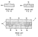
- Fig. 2 is a diagrammatic side elevational view, in vertically foreshortened form, of a fuel cell stack employing the prior art single pass internal electrolyte supply system having single electrolyte flow holes at alternating opposite ends of single electrolyte flow grooves on the anode side of one bipolar plate of the cell stack which together define a back and forth serpentine electrolyte flow path through the stack.
- Figs. 3 and 4 are plan views of respective top anode and bottom cathode sides of one bipolar plate of the stack of Fig. 2, the plate being reversible and having electrolyte flow holes at the left ends of the respective electrolyte flow grooves.
- Figs. 5 and 6 are plan views of respective top anode and bottom cathode sides of the bipolar plate of Figs. 3 and 4 after being reversed by rotating it 180 degrees about a vertical axis.
- Figs. 7 and 8 are plan views of respective top and bottom sides of a typical one of the cooling plates of the stack of Fig. 2, the plate being reversible and having a pair of electrolyte flow holes being alignable with either the left or right ends of the respective electrolyte flow grooves and with the electrolyte flow holes of either of the bipolar plates of Figs. 3-6.
- Fig. 9 is a cross-sectional view of the bipolar plate of the stack of Fig. 2 taken along line 9-9 of Fig. 3 across the electrolyte flow holes of the plate.
- Fig. 10 is another cross-sectional view of the same bipolar plate taken along line 10-10 of Fig. 3 across the electrolyte flow grooves of the plate.
- Fig. 11 is an enlarged cross-sectional view of a typical fuel cell of the stack of Fig. 2.
- Fig. 12 is a diagrammatic end elevational view, in vertically foreshortened form, of a fuel cell stack of an embodiment employing an internal electrolyte supply system having by-pass electrolyte flow passages at opposite ends of a pair of dual electrolyte flow grooves on the anode side of one bipolar plate of the cell stack, the electrolyte transport wicks located in the grooves are not shown in the sake of clarity.
- Figs. 13 and 14 are plan views of respective top anode and bottom cathode sides of one bipolar plate of the stack of Fig. 12, the plate having electrolyte flow passages adjacent to the opposite ends of the respective dual electrolyte flow grooves and with an electrolyte transport wick being shown in only one of the outboard ones of the dual grooves.
- Fig. 15 is an enlarged fragmentary view of the lower left corner of the bipolar plate of Fig. 13, showing the channels interconnecting the dual electrolyte flow grooves and the electrolyte cascade flow step interconnecting the passage and inboard ones of the dual grooves of the plate.
- Fig. 16 is a fragmentary cross-sectional view of the bipolar plate taken along line 16-16 of Fig. 14 through the dual electrolyte flow grooves.
- Fig. 17 is another fragmentary cross-sectional view of the same bipolar plate taken along line 17-17 of Fig. 15 through the dual electrolyte flow grooves and the channel interconnecting them.
- Fig. 18 is yet another fragmentary cross-sectional view of the same bipolar plate taken along line 18-18 of Fig. 15 across the electrolyte cascade flow step interconnecting the passage and inboard ones of the dual grooves of the plate.
- Fig. 19 is still another fragmentary longitudinal sectional view of the same bipolar plate taken along line 19-19 of Fig. 15 through the electrolyte cascade flow step of the plate.
- Figs. 20 and 21 are plan views of respective top anode and bottom cathode sides of another bipolar plate of the stack of Fig. 12, the plate having electrolyte flow passages adjacent to the opposite ends of the respective dual electrolyte flow grooves and with an electrolyte transport wick being shown in only one of the inboard ones of the dual grooves.
- Fig. 22 is an enlarged fragmentary view of the lower left corner of the bipolar plate of Fig. 20, showing the channels interconnecting the dual electrolyte flow grooves and the electrolyte cascade flow step interconnecting the passage and outboard ones of the dual grooves of the plate.
- Fig. 23 is a fragmentary cross-sectional view of the bipolar plate taken along line 23-23 of Fig. 22 through the dual electrolyte flow grooves.
- Fig. 24 is another fragmentary cross-sectional view of the same bipolar plate taken along line 24-24 of Fig. 22 through the dual electrolyte flow grooves and the channel interconnecting them.
- Fig. 25 is yet another fragmentary cross-sectional view of the same bipolar plate taken along line 25-25 of Fig. 22 across the electrolyte cascade flow step interconnecting the passage and outboard ones of the dual grooves of the plate.
- Fig. 26 is still another fragmentary longitudinal sectional view of the same bipolar plate taken along line 26-26 of Fig. 22 through the electrolyte cascade flow step of the plate.
- Fig. 27 is an enlarged fragmentary cross-sectional view of a typical fuel cell of the stack of Fig. 12 employing the bipolar plate of Fig. 13.
- Fig. 28 is an enlarged fragmentary cross-sectional view of a typical fuel cell of the stack of Fig. 12 employing the bipolar plate of Fig. 20.
- Fig. 29 is a diagrammatic end elevational view, in vertically foreshortened form, of a fuel cell stack of a second embodiment employing an internal electrolyte supply system having by-pass electrolyte flow passages at opposite ends of single electrolyte flow grooves on the anode side of one bipolar plate of the cell stack, the electrolyte transport wicks located in the grooves are not shown in the sake of clarity.
- Figs. 30 and 31 are plan views of respective top anode and bottom cathode sides of one bipolar plate of the stack of Fig. 29, the plate having electrolyte flow passages adjacent to the opposite ends of the respective electrolyte flow grooves and electrolyte transport wicks in the grooves.
- Figs. 32 and 33 are plan views of respective top anode and bottom cathode sides of the bipolar plate of Figs. 30 and 31 after being reversed by rotating it 180 degrees about a vertical axis.
- Figs. 34 and 35 are enlarged fragmentary views of the upper and lower left corners of the bipolar plate of Fig. 30, showing the electrolyte flow grooves and the electrolyte cascade flow steps interconnecting the passages and grooves of the plate.
- Fig. 36 is a fragmentary cross-sectional view of the bipolar plate taken along line 36-36 of Fig. 34 across the electrolyte cascade flow step interconnecting the passage and groove of the plate.
- Fig. 37 is another fragmentary longitudinal sectional view of the same bipolar plate taken along line 37-37 of Fig. 34 through the electrolyte flow step of the plate.
- Fig. 38 is yet another fragmentary cross-sectional view of the same bipolar plate taken along line 38-38 of Fig. 34 across the electrolyte flow groove of the plate, and
- Fig. 39 is an enlarged fragmentary cross-sectional view of a typical fuel cell of the stack of Fig. 29 employing the bipolar plate of Fig. 13.
- In the following description, like reference characters designate like or corresponding parts throughout the several views. Also, in the following description, it is to be understood that such terms as "forward", "rearward", "left", "right", "upwardly", "downwardly", and the like, are words of convenience and are not to be construed as limiting terms.
- Referring now to the drawings, and particularly to Fig. 1, there is shown an electrochemical fuel cell stack module, generally designated by the numeral 10, which includes a plurality of fuel cell stacks 12. Each
fuel cell stack 12 contains a multiplicity of repeating fuel cells. One of the prior art fuel cells is diagrammatically illustrated in Fig. 11 and designated as 14, whereas respective fuel cells incorporating features of the various embodiments of the present invention are diagrammatically illustrated in Figs. 27, 28 and 39 and identified by reference numerals to be designated later in the description of those embodiments. - For maintaining the fuel cell stacks 12 supplied with electrolyte, the fuel
cell stack module 10 also includes anelectrolyte reservoir 16, adistribution block 18, and apump 20 for supplying electrolyte from thereservoir 16 via aprimary supply line 22 to thedistribution block 18. The fuel cell stacks 12 are connected individually in flow communication with theelectrolyte distribution block 18 andreservoir 16 by respectivestack supply lines 24 and return or drain lines 26. Specifically, thedistribution block 18 includes an electrolyte chamber (not shown) for eachstack 12 in themodule 10 and a single overflow chamber (not shown). Thestack supply lines 24 interconnect electrolyte fill holes (not shown in Fig. 1) in the top of therespective stacks 12 with the distribution block electrolyte chambers, whereas anoverflow return line 28 connects the electrolyte overflow chamber of thedistribution block 18 with thereservoir 16. For a more detailed description of this electrolyte supply system associated with themodule 10, attention is directed to the first application cross-referenced above, the disclosure of which is incorporated herein by reference. - In operation, a predetermined electrolyte volume is forced by the
pump 20 through theprimary supply line 22 to thedistribution block 18. Within theblock 18, an equal amount of electrolyte is delivered to each electrolyte chamber. Excess electrolyte flows into the overflow chamber and is returned to thereservoir 16 through theoverflow return line 28. Electrolyte from the chambers is delivered through thestack supply lines 24 to the fill holes in the tops of the respective stacks 12. - In order to avoid creation of a short circuit through the electrically-conductive electrolyte, and damage to the fuel cell stacks 12, electrolyte is delivered in predetermined periodic pulses of short duration by the
pump 20 rather than by continuous flow. Gravitational force assists circulation of electrolyte through the fill holes and the internal supply system (both, the prior art embodiment in Fig. 2 and the various embodiments of the improved system of the present invention in Figs. 12 and 29 to be described below) of the fuel cell stacks. Any electrolyte not absorbed passes out of thestacks 12 through the drain holes (not shown in Fig. 1) and is returned to thereservoir 16 through the drain lines 26. - As mentioned, each
fuel stack 12 of themodule 10 includes a multiplicity of repeating fuel cells, such as designated 14 in the case of the prior art illustrated in Fig. 11, being arranged such that each cell is electrically connected in series with one another in a conventional manner (not shown). Each fuel cell, whether the prior art one 14 of Fig. 11 which will now be described or any of the fuel cells (whose reference numerals will be identified later) of Figs. 27, 28 and 39 associated with the various embodiments of the present invention, shares the same basic components. Typically, each fuel cell, forexample cell 14 in Fig. 11, includes top and bottombipolar plates 30 between which are sandwiched alower anode electrode 32, an electrolyte-containingporous matrix 34 and anupper cathode electrode 36. Also, shims orgaskets 38 are ordinarily provided for sealing about the peripheries of the electrodes. - In an exemplary embodiment, each
bipolar plate 30 is composed of a relatively thick rigid material such as a compression molded graphite resin composite while eachelectrode matrix 34 is composed of thin tissue-like sheets made of porous graphite saturatable with an electrolytic acid, such as concentrated phosphoric acid. Many other materials and structures can also be used to compose the components of thefuel cell 14. - Preferably, hundreds of the repeating fuel cells 14 (again, only one is shown in Fig. 11) are united to form the
fuel cell stack 12. Thus, the topbipolar plate 30 of each fuel cell also acts as the bottombipolar plate 30 for the fuel cell immediately above it and the bottombipolar plate 30 of each fuel cell also acts as the top bipolar plate for the fuel cell immediately below it. Also, a full fuel cell stack typically includesend plates 40 in the form of half-bipolar plates, with a top half-bipolar plate 40 serving as the upper end plate and a bottom half-bipolar plate 40 serving as the lower end plate. Thestack 12 is held together top andbottom compression plates 42 which contain the aforementioned electrolyte fill and drain holes, designated 44 and 46 in Fig. 2. - The
bipolar plates 30 are typically provided on opposite sides with a set of process channels (not seen) including fuel channels on one side and oxidant channels on the other side. A fuel, such as hydrogen, organics or metals, flows through the fuel process channels, whereas an oxidant, such as a halogen, air or other oxygen-containing material, flows through the oxidant process channels. Fuel inlet and outlet manifolds (not shown) and oxidant inlet and outlet manifolds (not shown) are typically attached to respective inlet and outlet regions of the fuel cell stacks 12 in communication with the fuel and oxidant channels to provide fuel and oxidant flows to and from the stack. Electrical power and heat are generated by the interaction of the fuel and oxidant through theelectrodes electrolyte matrix 34. Anexemplary fuel cell 14 utilizes hydrogen fuel, air as the oxidant and phosphoric acid as the electrolyte. - A substantial amount of heat is generated by the electrochemical reaction and, accordingly, each of the
stacks 12 ordinarily includes cooling modules composed of a pair of plates 48, as seen in Fig. 2. Dependent upon the operating temperatures desired, the cooling modules are placed between thefuel cells 14 at selected positions within thestack 12. A cooling module may, for example, be placed at approximately seventy evenly spaced locations in thestack 12. Each module is preferably comprised of a material similar to that of thebipolar plates 30 and has air cooling passages (not shown) therethrough. - The prior art internal electrolyte supply system in the
fuel cell stack 12, as best seen overall in Fig. 2, interconnects thefill hole 44 in thetop compression plate 42 and thedrain hole 46 in the bottom compression plate and routes electrolyte through thestack 12 in a back and forth serpentine fashion. As also depicted in Figs. 3 to 6, typicalbipolar plates stack 12. Eachplate 30 has single electrolyte flow grooves 50 (see also Fig. 9) defined on its upper anode-supporting side along opposite longitudinal edges thereof. Also, electrolyte flow passages 52 (see also Fig. 10) extend through theplates 30 in communicative relation with corresponding ones of a pair of opposite ends of the grooves. - Additionally, each
upper cooling plate 48A of thestack 12 hassimilar grooves 54 andpassages 56 aligned with thepassages 56 of the nextupper plate 30 as shown in Fig. 2. Eachlower cooling plate 48B only has thepassages 56, as shown in Figs. 2, 7 and 8, aligned with thepassages 56 of theupper cooling plate 48A and with thegrooves 50 of the nextlower plate 30. - Only with the assistance of gravity, electrolyte flows through the
cells 14 of thestack 12 along the serpentine path defined by theflow grooves passages respective plates 30, 48. However, since there is only the single path by which the electrolyte can pass through thestack 12 for supplying electrolyte to all of the cells therein, it will be readily appreciated that if an obstruction should develop in one of the grooves, for instance due to the matrix 34 (Fig. 11) sagging into one of the grooves over time, the electrolyte will not reach those cells beyond or below the location of the blockage. Further, those cells above the blockage will become flooded once the head pressure of the electrolyte rises sufficiently. It is such problems that the embodiments of the improved internal electrolyte supply system of the present invention, which will now be described, are particularly suited to alleviate. - Referring now to Figs. 12 to 28, there is shown a
fuel cell stack 164, and the respective details thereof. Thestack 164 is composed of a multiplicity of repeatingfuel cells 166, two of which are partially seen in Figs. 27 and 28. Thefuel cell 166 includes top and bottombipolar plates 168 between which are sandwiched alower anode electrode 170, an electrolyte containingporous matrix 172 and anupper cathode electrode 174. Also, agasket 176 is ordinarily provided for sealing about the peripheries of the electrodes. - In this first embodiment, the internal electrolyte supply system in the
stack 164, as best seen overall in Fig. 12, interconnects the pairs offill holes 178 in opposite end portions of thetop compression plate 180 and the pairs of drain holes 182 in the opposite end portions of thebottom compression plate 180 of the stack. The first embodiment of the supply system routes electrolyte through thefuel cell stack 164 along a series of first paths each extending horizontally and directly through one of the fuel cells between thebipolar plates 168 thereof so as to expose electrolyte to thematrix 172 and along a series of second paths extending vertically through thestack 164 adjacent to opposite ends of the first horizontal paths. The second paths are in communicative flow relation to the first paths and adapted to supply electrolyte directly to the respective first paths. - More particularly, as shown in Figs. 13-14 and 20-21, the
bipolar plates stack 164 of Fig. 12 include two pairs of dualelectrolyte flow grooves auxiliary grooves 186 extend generally parallel to and are interconnected with theprimary grooves 184 by a series of spaced apart cross flow channels 188 (see also Figs. 15-17 and 22-24) defined in theplates intermittent walls 190 so as to provide the communicative flow relation therebetween. Also,primary grooves 184 are covered by thegasket 176, as seen in Figs. 27 and 28. Further, anelectrolyte transport wick 192 is disposed in theauxiliary grooves 186 of each cell (although only one wick is depicted in Fig. 13) and is engaged with and supports thematrix 172 thereof for facilitating transfer of electrolyte to thematrix 172. - However, the
bipolar plates stack 164 include means defined therein which supply electrolyte downwardly through the stack in a by-pass fashion and to theprimary grooves 184 so as to produce a cascading electrolyte flow. Such means includeelectrolyte flow passages 194 longitudinally aligned and spaced outwardly from the opposite ends of theauxiliary grooves 186 and extending through theplates primary grooves 184, and a dam or step 196 defined in the plates between the respectiveelectrolyte flow passage 194 andprimary groove 184. The steps 196 (see also Figs. 18-19 and 25-26) establish the communicative flow relation and produces the cascading electrolyte flow between thepassages 194 andprimary grooves 184. - Finally,
upper cooling plates 195 have thepassages 194 in their left end portions and thegroove 184,passages 194 andsteps 196 in their right end portions, whereaslower cooling plates 197 have onlypassages 194 in their left and right end portions. - The offset or displacement of the
passages 194 fromprimary grooves 184 via thesteps 196 provides a by-pass type arrangement and causes small pools of electrolyte to form in thegrooves bipolar plate 168 which overflow to the next lower plate. In this arrangement, no head pressure exists in the flow of electrolyte. - Turning now to Figs. 29 to 39, there is shown a
fuel cell stack 198, and the respective details thereof, incorporating an internal electrolyte supply system similar to that of the first embodiment just described. As before, thestack 198 is composed of a multiplicity of repeatingfuel cells 200, one of which is partially seen in Fig. 39. Thefuel cell 200 includes top and bottombipolar plates 202 between which are sandwiched alower anode electrode 204, an electrolyte-containingporous matrix 206 and anupper cathode electrode 208. Also, agasket 210 is ordinarily provided for sealing about the peripheries of the electrodes. - In this second embodiment, the internal electrolyte supply system in the
stack 198, as best seen overall Fig. 29, interconnects the pairs offill holes 212 in opposite end portions of thetop compression plate 214 and the pairs of drain holes 216 in the opposite end portions of thebottom compression plate 214 of the stack. The second embodiment of the supply system, being similar to the first embodiment, routes electrolyte through thefuel cell stack 198 along a series of first paths each extending horizontally and directly through one of the fuel cells between thebipolar plates 202 thereof so as to expose electrolyte to thematrix 206 and along a series of second paths extending vertically through thestack 198 adjacent to opposite ends of the first horizontal paths. The second paths are in communicative flow relation to the first paths and adapted to supply electrolyte directly to the respective first paths. However, the supply system also incorporates some modifications of the features found in the first embodiment as will become clearer below. - More particularly, as shown in Figs. 30-31 and 32-33, the
bipolar plates stack 198 of Fig. 29 are identical, with one plate merely being rotated about a longitudinalhorizontal axis 180 degrees with respect to the other plate. Theplates electrolyte flow grooves electrolyte flow passages 222 defined through opposite ends of the plates adjacent opposite ends of thegrooves electrolyte transport wick 224 is disposed in the straight and offsetgrooves matrix 206 thereof for facilitating transfer of electrolyte to the matrix. - Even though the
bipolar plates single grooves grooves electrolyte flow passages 222 transversely aligned and spaced laterally from the opposite ends of thegrooves electrolyte flow passage 194 and opposite ends of thegrooves passages 222 and thegrooves - Finally,
upper cooling plates 228 have one or the other of thegrooves passages 222 andsteps 226 in their left and right end portions, whereaslower cooling plates 230 have onlypassages 222 in their left and right end portions. - It, will be readily understood that an advantage of the second embodiment over the first embodiment is that the former requires only one bipolar plate design, whereas the latter requires two designs.
- It will be further understood by those having ordinary skill in the art that the respective gaskets associated with the fuel cells of the various embodiments of the present invention described above are provided with holes or openings therein which register with the by-pass openings in the bipolar plates for flow communication of the electrolyte through the fuel cell stacks.
Claims (11)
- A fuel cell stack (164; 198) having electrolyte feed and drain means and a plurality of stacked fuel cells (166; 200), each fuel cell including bipolar plates (168; 202) separating said fuel cell from adjacent fuel cells in said stack thereof, with an electrolyte-containing matrix (172; 206) disposed between said plates, and an internal electrolyte supply system interconnecting said feed ans drain means,
characterized
in that said system comprises(a) a first means defined repeatedly throughout the said fuel cell stack for flowing electrolyte along a series of first paths (184, 186; 218, 220) each extending horizontally and directly through one of said cells (166; 200) in said stack (164; 198) between said plates (168; 202) thereof so as to expose electrolyte to said matrix (172; 206) of said cell;(b) second means defined repeatedly throughout said fuel cell stack (164; 198) for flowing electrolyte along a series of second paths (194; 222) extending through said plates (168; 202) of said cell stack (164; 198) at opposite ends of said first horizontal paths (184, 186; 218, 220) and forming pools of electrolyte by means of dams or steps (196; 226) and the paths (184, 186; 218, 220), said second paths (194; 226) being in communication flow relation to said first paths (184, 186; 218, 220) and adapted to supply electrolyte in by-pass fashion directly to said respective first paths (184, 186; 218, 220); and(c) third means (194, 196; 222, 226) defined in said plates (168; 202) between said first and second means which establish said by-pass communication flow relation and produce a cascading flow therebetween. - A fuel cell stack (164, 198) according to claim 1, characterized in that the first means includes at least one electrolyte flow groove (184, 186; 218, 220) defined in one side of one of the plates (168A, 168B; 202A, 202B) of each cell for flowing electrolyte along the first path through each cell (166; 198).
- A fuel cell stack according to claim 2, characterized in that an electrolyte transport wick (192; 224) is disposed in one groove (186; 218, 220) of each cell and engaged with said matrix (172; 206) of said each cell (166; 198) for facilitating transfer of electrolyte to said matrix (172; 206).
- A fuel cell stack according to claim 2 or 3, characterized in that the second means includes an electrolyte flow passage (194; 226) extending through the plates (168A, 168B; 202A, 202B) of the cells (166; 200) in communicative flow relation with each opposite end of one of the electrolyte flow grooves (184, 186; 218, 220) defined therein.
- A fuel cell stack according to claim 4, characterized in that third means includes a step (196; 226) defined in each of the plates (168A, 168B; 202A, 202B) between the respective electrolyte flow passage (194; 226) and groove (184, 186; 218, 220) which establishes said communicative flow relation and produces said cascading electrolyte flow therebetween.
- A fuel cell stack according to claim 1, characterized in that the first means includes at least a pair of electrolyte flow grooves (184, 186) defined in side-by-side communicative flow relation in one side of one of the plates of each cell for flowing electrolyte along the first path through said cell.
- A fuel cell stack according to claim 6, characterized in that at least one cross channel (188) is defined in the one side of the plate (168) of each cell (166) between and interconnecting said pair of electrolyte flow grooves (184, 186) so as to provide the communicative flow relation therebetween.
- A fuel cell stack according to claim 6, characterized in that a series of spaced apart cross channels (188) defined in the one side of the one plate (168) of each cell between and interconnecting the pair of electrolyte flow grooves (184, 186) so as to provide the communicative flow relation therebetween.
- A fuel cell stack according to claim 6 characterized in that an electrolyte transport wick (192) is disposed in one (186) of the grooves of each cell (166) and engaged with said matrix (172) of said cell (166) for facilitating transfer of electrolyte to said matrix.
- A fuel cell stack according to claim 9, characterized in that the second means includes an electrolyte flow passage (188) extending through the plates of the cells in communicative flow relation with each opposite end of the other (186) of the electrolyte flow grooves (184, 186) defined therein which do not contain said wick (192).
- A fuel cell stack according to claim 6, characterized in that the third means includes a step (196) defined in each of the plates (168A, 168B) between the respective electrolyte flow passage (194) and the other (184) of the grooves which establishes said communicative flow relation and produces said cascading electrolyte flow therebetween.
Applications Claiming Priority (2)
| Application Number | Priority Date | Filing Date | Title |
|---|---|---|---|
| US06/940,320 US4732822A (en) | 1986-12-10 | 1986-12-10 | Internal electrolyte supply system for reliable transport throughout fuel cell stacks |
| US940320 | 1997-09-30 |
Publications (3)
| Publication Number | Publication Date |
|---|---|
| EP0274003A2 EP0274003A2 (en) | 1988-07-13 |
| EP0274003A3 EP0274003A3 (en) | 1989-03-08 |
| EP0274003B1 true EP0274003B1 (en) | 1992-10-14 |
Family
ID=25474626
Family Applications (1)
| Application Number | Title | Priority Date | Filing Date |
|---|---|---|---|
| EP87111437A Expired - Lifetime EP0274003B1 (en) | 1986-12-10 | 1987-08-07 | Improved internal electrolyte supply system for reliable transport throughout fuel cell stack |
Country Status (6)
| Country | Link |
|---|---|
| US (1) | US4732822A (en) |
| EP (1) | EP0274003B1 (en) |
| JP (1) | JPS63155562A (en) |
| CA (1) | CA1285316C (en) |
| DE (1) | DE3782234T2 (en) |
| ZA (1) | ZA875933B (en) |
Families Citing this family (34)
| Publication number | Priority date | Publication date | Assignee | Title |
|---|---|---|---|---|
| US4942099A (en) * | 1988-11-28 | 1990-07-17 | Kabushiki Kaisha Toshiba | Fuel cell |
| JP2501169B2 (en) * | 1993-03-18 | 1996-05-29 | 株式会社日立製作所 | Fuel cell, electrolyte supply container, and electrolyte supply method |
| US5376472A (en) * | 1993-10-06 | 1994-12-27 | Ceramatec, Inc. | Semi-internally manifolded interconnect |
| US5480738A (en) * | 1994-02-04 | 1996-01-02 | Ceramatec, Inc. | Fuel cell module |
| US5763114A (en) * | 1994-09-01 | 1998-06-09 | Gas Research Institute | Integrated reformer/CPN SOFC stack module design |
| US5612149A (en) * | 1996-01-02 | 1997-03-18 | Ceramatec, Inc. | Fuel cell column heat exchanger mated module |
| JP3580455B2 (en) * | 1996-03-25 | 2004-10-20 | 石川島播磨重工業株式会社 | Molten carbonate fuel cell and power generator using the same |
| US7682714B2 (en) * | 2001-05-25 | 2010-03-23 | Toyota Jidosha Kabushiki Kaisha | Connecting structure of a cell monitor connector to a fuel cell stack |
| US20040001991A1 (en) * | 2002-07-01 | 2004-01-01 | Kinkelaar Mark R. | Capillarity structures for water and/or fuel management in fuel cells |
| ATE324673T1 (en) * | 2002-11-18 | 2006-05-15 | Gencell Corp | BIPOLAR PLATE WITH TWO PASS ANODE |
| US20050202305A1 (en) * | 2004-02-24 | 2005-09-15 | Markoski Larry J. | Fuel cell apparatus and method of fabrication |
| US7524575B2 (en) * | 2004-06-07 | 2009-04-28 | Hyteon Inc. | Flow field plate for use in fuel cells |
| US7531264B2 (en) * | 2004-06-07 | 2009-05-12 | Hyteon Inc. | Fuel cell stack with even distributing gas manifolds |
| US20060008695A1 (en) * | 2004-07-09 | 2006-01-12 | Dingrong Bai | Fuel cell with in-cell humidification |
| US20060088744A1 (en) * | 2004-09-15 | 2006-04-27 | Markoski Larry J | Electrochemical cells |
| US7314680B2 (en) * | 2004-09-24 | 2008-01-01 | Hyteon Inc | Integrated fuel cell power module |
| US7479333B2 (en) * | 2004-12-13 | 2009-01-20 | Hyteon, Inc. | Fuel cell stack with multiple groups of cells and flow passes |
| US20060188763A1 (en) * | 2005-02-22 | 2006-08-24 | Dingrong Bai | Fuel cell system comprising modular design features |
| US8158300B2 (en) * | 2006-09-19 | 2012-04-17 | Ini Power Systems, Inc. | Permselective composite membrane for electrochemical cells |
| US20080145723A1 (en) * | 2006-12-15 | 2008-06-19 | General Electric Company | Rechargeable fuel cell and method |
| US7985505B2 (en) * | 2006-12-15 | 2011-07-26 | General Electric Company | Fuel cell apparatus and associated method |
| US8343687B2 (en) * | 2006-12-19 | 2013-01-01 | General Electric Company | Rechargeable fuel cell system |
| US20080248343A1 (en) * | 2007-04-02 | 2008-10-09 | Markoski Larry J | Microfluidic fuel cells |
| US8551667B2 (en) * | 2007-04-17 | 2013-10-08 | Ini Power Systems, Inc. | Hydrogel barrier for fuel cells |
| US20090035644A1 (en) * | 2007-07-31 | 2009-02-05 | Markoski Larry J | Microfluidic Fuel Cell Electrode System |
| WO2009017150A1 (en) * | 2007-08-02 | 2009-02-05 | Sony Corporation | Fuel cell stack system, channel structure, fuel cell, electrode, and electronic device |
| US8163429B2 (en) * | 2009-02-05 | 2012-04-24 | Ini Power Systems, Inc. | High efficiency fuel cell system |
| JP4916536B2 (en) * | 2009-08-06 | 2012-04-11 | 日立オムロンターミナルソリューションズ株式会社 | IC card processing device |
| US8783304B2 (en) | 2010-12-03 | 2014-07-22 | Ini Power Systems, Inc. | Liquid containers and apparatus for use with power producing devices |
| US9065095B2 (en) | 2011-01-05 | 2015-06-23 | Ini Power Systems, Inc. | Method and apparatus for enhancing power density of direct liquid fuel cells |
| GB2515994A (en) * | 2013-04-08 | 2015-01-14 | Acal Energy Ltd | Fuel cells |
| JP2018073715A (en) * | 2016-11-02 | 2018-05-10 | マグネクス株式会社 | Fuel cell end plate |
| KR102602415B1 (en) * | 2018-09-04 | 2023-11-14 | 현대자동차주식회사 | Membrane Electrode Assembly |
| US11444298B2 (en) | 2019-07-18 | 2022-09-13 | Hyaxiom, Inc. | Electrolyte shunt migration management in a fuel cell stack |
Family Cites Families (30)
| Publication number | Priority date | Publication date | Assignee | Title |
|---|---|---|---|---|
| US3239384A (en) * | 1963-01-23 | 1966-03-08 | Corson G & W H | Liquid ammonia deferred action electric-current producing cell |
| DE1496330C3 (en) * | 1965-06-16 | 1975-10-02 | Varta Batterie Ag, 3000 Hannover | Pressurized gas-operated, load-dependent pump for circulating gases and liquids in fuel elements |
| FR2287784A1 (en) * | 1974-10-09 | 1976-05-07 | Inst Francais Du Petrole | ADVANCED FUEL CELL |
| FR2302600A1 (en) * | 1975-02-25 | 1976-09-24 | Inst Francais Du Petrole | NEW IMPROVEMENT IN FUEL CELLS |
| BE868387A (en) * | 1977-06-29 | 1978-12-27 | Electrochem Energieconversie | BATTERY UNIT CONTAINING ONE OR MORE FUEL CELL BLOCKS |
| US4168349A (en) * | 1978-04-27 | 1979-09-18 | Westinghouse Electric Corp. | Iron/air battery system having circulating electrolyte and a horizontal cell configuration |
| FR2442517A1 (en) * | 1978-11-24 | 1980-06-20 | Inst Francais Du Petrole | METHOD AND DEVICE FOR FEEDING A FUEL CELL WITH REACTIVE PRODUCTS |
| US4324844A (en) * | 1980-04-28 | 1982-04-13 | Westinghouse Electric Corp. | Variable area fuel cell cooling |
| US4292379A (en) * | 1980-04-28 | 1981-09-29 | Westinghouse Electric Corp. | Variable area fuel cell process channels |
| US4276355A (en) * | 1980-04-28 | 1981-06-30 | Westinghouse Electric Corp. | Fuel cell system configurations |
| JPS5755071A (en) * | 1980-09-20 | 1982-04-01 | Hitachi Ltd | Fuel cell laminate |
| US4414291A (en) * | 1980-12-24 | 1983-11-08 | United Technologies Corporation | Method for reducing electrolyte loss from an electrochemical cell |
| US4342816A (en) * | 1981-04-22 | 1982-08-03 | The United States Of America As Represented By The United States Department Of Energy | Fuel cell stack arrangements |
| JPS5823166A (en) * | 1981-08-04 | 1983-02-10 | Mitsubishi Electric Corp | Fuel cell |
| JPS5842179A (en) * | 1981-09-08 | 1983-03-11 | Hitachi Ltd | Fuel battery |
| US4366211A (en) * | 1981-09-21 | 1982-12-28 | Westinghouse Electric Corp. | Control of electrolyte fill to fuel cell stack |
| US4383009A (en) * | 1981-09-21 | 1983-05-10 | The United States Of America As Represented By The United States Department Of Energy | Low hydrostatic head electrolyte addition to fuel cell stacks |
| JPS58103784A (en) * | 1981-12-16 | 1983-06-20 | Hitachi Ltd | Fuel cell |
| JPS58164151A (en) * | 1982-03-25 | 1983-09-29 | Kansai Electric Power Co Inc:The | Electrolyte feeding device of matrix type fuel cell |
| US4463068A (en) * | 1982-09-30 | 1984-07-31 | Engelhard Corporation | Fuel cell and system for supplying electrolyte thereto with wick feed |
| US4463066A (en) * | 1982-09-30 | 1984-07-31 | Engelhard Corporation | Fuel cell and system for supplying electrolyte thereto |
| US4463067A (en) * | 1982-09-30 | 1984-07-31 | Engelhard Corporation | Fuel cell and system for supplying electrolyte thereto utilizing cascade feed |
| US4467019A (en) * | 1982-09-30 | 1984-08-21 | Engelhard Corporation | Fuel cell with electrolyte feed system |
| JPS59151771A (en) * | 1983-02-16 | 1984-08-30 | Sanyo Electric Co Ltd | Electrolyte supply device of fuel cell |
| US4481266A (en) * | 1983-03-25 | 1984-11-06 | Littauer Ernest L | Reactive metal battery having continuous supply of cathode reactant |
| JPS59217958A (en) * | 1983-05-25 | 1984-12-08 | Fuji Electric Corp Res & Dev Ltd | Device for supplying electrolyte for matrix-type fuel cell |
| JPS60150560A (en) * | 1984-01-18 | 1985-08-08 | Fuji Electric Corp Res & Dev Ltd | Electrolyte supply apparatus of matrix type fuel battery |
| JPS60198059A (en) * | 1984-03-21 | 1985-10-07 | Fuji Electric Corp Res & Dev Ltd | Electrolyte supply structure of matrix type fuel cell |
| JPH0630253B2 (en) * | 1985-03-22 | 1994-04-20 | 株式会社日立製作所 | Fuel cell |
| US4572876A (en) * | 1985-04-01 | 1986-02-25 | Westinghouse Electric Corp. | Apparatus for supplying electrolyte to fuel cell stacks |
-
1986
- 1986-12-10 US US06/940,320 patent/US4732822A/en not_active Expired - Lifetime
-
1987
- 1987-08-07 EP EP87111437A patent/EP0274003B1/en not_active Expired - Lifetime
- 1987-08-07 DE DE8787111437T patent/DE3782234T2/en not_active Expired - Fee Related
- 1987-08-11 ZA ZA875933A patent/ZA875933B/en unknown
- 1987-09-08 JP JP62225107A patent/JPS63155562A/en active Pending
- 1987-12-08 CA CA000553834A patent/CA1285316C/en not_active Expired - Lifetime
Also Published As
| Publication number | Publication date |
|---|---|
| US4732822A (en) | 1988-03-22 |
| CA1285316C (en) | 1991-06-25 |
| DE3782234D1 (en) | 1992-11-19 |
| JPS63155562A (en) | 1988-06-28 |
| EP0274003A3 (en) | 1989-03-08 |
| ZA875933B (en) | 1988-02-22 |
| DE3782234T2 (en) | 1993-04-15 |
| EP0274003A2 (en) | 1988-07-13 |
Similar Documents
| Publication | Publication Date | Title |
|---|---|---|
| EP0274003B1 (en) | Improved internal electrolyte supply system for reliable transport throughout fuel cell stack | |
| US6582844B2 (en) | Method of cooling a fuel cell | |
| EP0521830B1 (en) | Fully internal manifolded fuel cell stack | |
| US6383347B1 (en) | Electrochemical cell utilizing rigid support members | |
| US5750281A (en) | Edge manifold assembly for an electrochemical fuel cell stack | |
| US6558832B1 (en) | Fuel cell module | |
| US4853301A (en) | Fuel cell plates with skewed process channels for uniform distribution of stack compression load | |
| US4631239A (en) | Fuel cell plates with improved arrangement of process channels for enhanced pressure drop across the plates | |
| JP4081428B2 (en) | Fuel cell | |
| JP2008536258A (en) | Arrangement of flow field plate | |
| JP3553245B2 (en) | Direct methanol fuel cell | |
| US10680255B2 (en) | Flow-guiding plate for a fuel cell | |
| JP2007134206A (en) | Fuel cell stack | |
| JP2009009837A (en) | Fuel cell | |
| JP2001143724A (en) | Fuel cell | |
| CA2330946A1 (en) | Fuel cell stack assembly | |
| KR101119479B1 (en) | Bipolar separator for fuel cell stack | |
| US7354674B2 (en) | Electrode structure for stacked alkaline fuel cells | |
| GB2336937A (en) | Stack assembly primarily for an electrochemical cell | |
| JP4109569B2 (en) | Fuel cell | |
| EP1646099B1 (en) | Electrochemical device | |
| CA2435571A1 (en) | Electrolysis device | |
| US20030170528A1 (en) | Moldable separator plate for electrochemical devices and cells | |
| JP2007234405A (en) | Fuel cell stack | |
| CN216958101U (en) | Parallel fuel cell stack |
Legal Events
| Date | Code | Title | Description |
|---|---|---|---|
| PUAI | Public reference made under article 153(3) epc to a published international application that has entered the european phase |
Free format text: ORIGINAL CODE: 0009012 |
|
| AK | Designated contracting states |
Kind code of ref document: A2 Designated state(s): DE FR GB NL SE |
|
| PUAL | Search report despatched |
Free format text: ORIGINAL CODE: 0009013 |
|
| AK | Designated contracting states |
Kind code of ref document: A3 Designated state(s): DE FR GB NL SE |
|
| 17P | Request for examination filed |
Effective date: 19890321 |
|
| 17Q | First examination report despatched |
Effective date: 19901112 |
|
| GRAA | (expected) grant |
Free format text: ORIGINAL CODE: 0009210 |
|
| AK | Designated contracting states |
Kind code of ref document: B1 Designated state(s): DE FR GB NL SE |
|
| ET | Fr: translation filed | ||
| REF | Corresponds to: |
Ref document number: 3782234 Country of ref document: DE Date of ref document: 19921119 |
|
| PLBE | No opposition filed within time limit |
Free format text: ORIGINAL CODE: 0009261 |
|
| STAA | Information on the status of an ep patent application or granted ep patent |
Free format text: STATUS: NO OPPOSITION FILED WITHIN TIME LIMIT |
|
| REG | Reference to a national code |
Ref country code: FR Ref legal event code: TP |
|
| 26N | No opposition filed | ||
| NLS | Nl: assignments of ep-patents |
Owner name: ENVIRONMENTAL ENERGY SYSTEMS, INC. TE LARGE, PENNS |
|
| EAL | Se: european patent in force in sweden |
Ref document number: 87111437.7 |
|
| PGFP | Annual fee paid to national office [announced via postgrant information from national office to epo] |
Ref country code: FR Payment date: 19980619 Year of fee payment: 12 |
|
| PGFP | Annual fee paid to national office [announced via postgrant information from national office to epo] |
Ref country code: SE Payment date: 19980624 Year of fee payment: 12 Ref country code: GB Payment date: 19980624 Year of fee payment: 12 |
|
| PGFP | Annual fee paid to national office [announced via postgrant information from national office to epo] |
Ref country code: NL Payment date: 19980730 Year of fee payment: 12 |
|
| PGFP | Annual fee paid to national office [announced via postgrant information from national office to epo] |
Ref country code: DE Payment date: 19980930 Year of fee payment: 12 |
|
| PG25 | Lapsed in a contracting state [announced via postgrant information from national office to epo] |
Ref country code: GB Free format text: LAPSE BECAUSE OF NON-PAYMENT OF DUE FEES Effective date: 19990807 |
|
| PG25 | Lapsed in a contracting state [announced via postgrant information from national office to epo] |
Ref country code: SE Free format text: THE PATENT HAS BEEN ANNULLED BY A DECISION OF A NATIONAL AUTHORITY Effective date: 19990830 |
|
| PG25 | Lapsed in a contracting state [announced via postgrant information from national office to epo] |
Ref country code: NL Free format text: LAPSE BECAUSE OF NON-PAYMENT OF DUE FEES Effective date: 20000301 |
|
| GBPC | Gb: european patent ceased through non-payment of renewal fee |
Effective date: 19990807 |
|
| PG25 | Lapsed in a contracting state [announced via postgrant information from national office to epo] |
Ref country code: FR Free format text: LAPSE BECAUSE OF NON-PAYMENT OF DUE FEES Effective date: 20000428 |
|
| EUG | Se: european patent has lapsed |
Ref document number: 87111437.7 |
|
| NLV4 | Nl: lapsed or anulled due to non-payment of the annual fee |
Effective date: 20000301 |
|
| PG25 | Lapsed in a contracting state [announced via postgrant information from national office to epo] |
Ref country code: DE Free format text: LAPSE BECAUSE OF NON-PAYMENT OF DUE FEES Effective date: 20000601 |
|
| REG | Reference to a national code |
Ref country code: FR Ref legal event code: ST |