EP0273757A2 - Bildlesegerät - Google Patents
Bildlesegerät Download PDFInfo
- Publication number
- EP0273757A2 EP0273757A2 EP87311491A EP87311491A EP0273757A2 EP 0273757 A2 EP0273757 A2 EP 0273757A2 EP 87311491 A EP87311491 A EP 87311491A EP 87311491 A EP87311491 A EP 87311491A EP 0273757 A2 EP0273757 A2 EP 0273757A2
- Authority
- EP
- European Patent Office
- Prior art keywords
- film
- light source
- light
- adjusting board
- reading apparatus
- Prior art date
- Legal status (The legal status is an assumption and is not a legal conclusion. Google has not performed a legal analysis and makes no representation as to the accuracy of the status listed.)
- Granted
Links
Images
Classifications
-
- H—ELECTRICITY
- H04—ELECTRIC COMMUNICATION TECHNIQUE
- H04N—PICTORIAL COMMUNICATION, e.g. TELEVISION
- H04N1/00—Scanning, transmission or reproduction of documents or the like, e.g. facsimile transmission; Details thereof
- H04N1/40—Picture signal circuits
- H04N1/40056—Circuits for driving or energising particular reading heads or original illumination means
Definitions
- the present invention relates to an image reading apparatus and more particularly, to an image reading apparatus such as a color copier and a color scanner used to read a transparent film.
- an image reading apparatus for reading a transparent film comprises a light source, an exchangeable adjusting board corresponding to the transmission factor of the film, imaging means for receiving and imaging the light passing through the adjusting board and the film, comparison means for detecting the output of the imaging means and comparing the output of the imaging means with a predetermined output level, control means for outputting power source control signals according to the output of the comparison means, a power source for energizing the light source according to the power source control signals, wherein the adjusting board is imaged before the film is imaged by the imaging means, and, in case the light amount of the light source is not adequate to the film, the extent of energizing the light source is adjusted so as to be adequate to image the film.
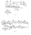
- FIG. 1 is a block diagram showing a constitution of an image reading apparatus as a preferred embodiment of the present invention.
- a film 11 to be read and imaged is set on the second adjusting board 12b mounted on a transparent board 13.
- the first adjusting board 12a is set.
- the first adjusting board 12a is made preferablly of milk-white resin.
- the first adjusting board 12a and the second adjusting board 12b (when 12a and 12b are generically referred, hereinafter shown as 12) are provided for the purpose of diffusing and homogenizing light from a light source 14.
- the board 13 moves horizontally in the direction of arrows c or d in FIG. 1.
- Power sources 14R, 14G, and 14B which individually emit red, green and blue light respectively (when 14R, 14G, anf 14B are generically referred, shown as 14) are provided below the board 13. Light from the light source 14 irradiates the film 11 through the board 13.
- the light source 14 has a length corresponding to the width of the board 13 and is a linear light source, preferably a fluorescent lamp.
- a first red light source 14R is switched on and the red light passing through the board 13 is diffused and uniformly radiated within the first adjusting board 12a to pass through the left side C of the first adjusting board 12a.
- the board 13 moves in the direction of arrow c (to the left) in FIG. 1 from the point C as a base point.
- the red light from the red light source 14R scans the first adjusting board to its right side D, and after that, scans the film 11 from its left side E to its right side F. After the red light source 14 R reaches the right side F, it is switched off. At the same time, the board 13 moves in the direction of arrow d (to the right) in FIG. 1 back to the base point C.
- the green light source 14 G is switched on and scans in the same way as the red light source, and at last the blue light source 14B is switched on and scans in the same way, to finalize the scan of the film 11 by all of the light sources 14R, 14G, and 14B.
- the light from the light source 14 first passes through the first adjusting board 12a and as shown by line m1, reaches a reflection mirror 16. As shown by line m2, it is reflected and passes through the lens 17 to be introduced to an imaging means 18, preferably charge-coupled device (CCD). Then, successively and sequentially, the light passing through the film 11 on the second adjusting board 12b is introduced in the same way as shown by lines m1 and m2. In this way, first, information regarding the white balance from the first adjusting board 12a is introduced to line n1 after converted to corresponding electrical signals, and then, information regarding the color and tone of the film 11 on the second adjusting board 12b is introduced to the line n1 after converted to the corresponding electrical signal. According to the abovementioned electrical signals, controlling is made as described below, and then, the image is processed by an image processing apparatus(not shown in the figures).
- an image processing apparatus not shown in the figures.
- the light from the light source 14 is reflected only once by the reflection mirror 16, but the reflection may not be restricted to be only once, and it may be possible to use several reflection mirrors to lead the light in a desired direction. Also, a lens 17 provided on the optical path may not be restricted to be only at one place.
- light source is a linear light source, but surface light source and imaging means for surface-reading may be used to avoid moving the above board 13.
- FIG. 2 is a block diagram showing an electrical constitution of an image reading apparatus as a preferred embodiment of the present invention.
- the board 13 and the lens 17 are omitted and light reflection is made only once by the reflection mirror 16.
- the output of the imaging means 18 is amplified by an amplifier 19 and is inputted to a comparator 20 as a comparison means used to detect and compare the output of the imaging means 18 with a predetermined level.
- the controlling portion 21 as a controlling means which outputs power controlling signals sequentially inputs pulse controlling signals to the power source 22 which energizes the light source by power source controlling signals so that the light amount of the light source 14 is adjusted.
- the controlling signals are determined by the abovementioned output level of the comparator 20 '0' or '1'.
- the controlling portion 21 gives the controlling signal Pw to the power source 22.
- the light emitted from the light source 14R passes through the first adjusting board 12a and reaches the reflection mirror 16 as shown by line m1, and then is reflected and introduced to the imaging means 18 as shown by line m2.
- the imaging means 18 corresponds to the 'white' portion of the film, which means the condition of white balance. If, in this condition, the output level of the comparator 20 is logic '0,' the output level is too low, so the controlling portion 21 increases the level of the controlling signal Pw to the power source 22 so that the following relation is satisfied.
- the first adjusting board have a good transmission factor and, for example, the output level of the comparator 20 is logic '1' at the level (1/2)
- a quantity between 1/2 and 1/16 is sequentially subtracted until the output level of the comparator 20 becomes logic '0.
- the controlling signal Pw corresponding to 3/16 of the rated largest light amount is given to the power source 22. The extent of energizing the light source 14 is thus determined and white balance adjustment is completed.
- the red light source 14R then scans the film 11 on the second adjusting board 12b from its left side E. After reading the red part of the film 11 to the right side F, the red light source 14R is switched off and at the same time, the board not shown in the figures goes in the direction of arrow d (to the right in FIG. 2) back to the base point C, the left side of the first adjusting board 12a. Then, the green light source 14G is switched on. The green light source 14G executes white balance adjustment and scanning of film 11 in the same way as the red light source 14R does. Then, the blue light source 14B is switched on and executes the same action. The reading of the film 11 by the three primary color lights 14R, 14G, and 14B is thus completed.
- the film to be read is a color positive film, but the present invention can also be applied to a negative film.
- white balance adjustment may be done regarding only the first color (for example, red) light.
- any control for example, manual keyboard or switch means may be provided for presenting information of the light transmission factor of the film into the control means.
Landscapes
- Engineering & Computer Science (AREA)
- Multimedia (AREA)
- Signal Processing (AREA)
- Facsimiles In General (AREA)
- Facsimile Scanning Arrangements (AREA)
- Facsimile Image Signal Circuits (AREA)
- Optical Systems Of Projection Type Copiers (AREA)
- Control Of Exposure In Printing And Copying (AREA)
- Image Input (AREA)
Applications Claiming Priority (2)
| Application Number | Priority Date | Filing Date | Title |
|---|---|---|---|
| JP61311207A JPS63166355A (ja) | 1986-12-27 | 1986-12-27 | 読取り装置 |
| JP311207/86 | 1986-12-27 |
Publications (3)
| Publication Number | Publication Date |
|---|---|
| EP0273757A2 true EP0273757A2 (de) | 1988-07-06 |
| EP0273757A3 EP0273757A3 (en) | 1988-10-05 |
| EP0273757B1 EP0273757B1 (de) | 1990-12-12 |
Family
ID=18014391
Family Applications (1)
| Application Number | Title | Priority Date | Filing Date |
|---|---|---|---|
| EP87311491A Expired EP0273757B1 (de) | 1986-12-27 | 1987-12-29 | Bildlesegerät |
Country Status (5)
| Country | Link |
|---|---|
| US (1) | US4845531A (de) |
| EP (1) | EP0273757B1 (de) |
| JP (1) | JPS63166355A (de) |
| CA (1) | CA1328011C (de) |
| DE (1) | DE3766697D1 (de) |
Families Citing this family (4)
| Publication number | Priority date | Publication date | Assignee | Title |
|---|---|---|---|---|
| US5218402A (en) * | 1991-09-17 | 1993-06-08 | Eastman Kodak Company | Color image reproduction with compensating light source |
| US5269871A (en) * | 1991-10-28 | 1993-12-14 | Minnesota Mining And Manufacturing Company | Tape applying device |
| JPH0641478U (ja) * | 1992-11-20 | 1994-06-03 | ダイワ精工株式会社 | 魚釣用両軸受型リ−ルの制動装置 |
| DE19731531B4 (de) * | 1997-07-23 | 2006-02-16 | Bts Holding International Bv | Infrarotabtastung von Perforationslöchern |
Family Cites Families (8)
| Publication number | Priority date | Publication date | Assignee | Title |
|---|---|---|---|---|
| DE2816325A1 (de) * | 1978-04-14 | 1979-10-18 | Computer Ges Konstanz | Einrichtung zum abtasten von mustern mit einer geregelten lichtquelle |
| JPS60216667A (ja) * | 1984-04-11 | 1985-10-30 | Sharp Corp | 画像読取装置のccdセンサ出力回路 |
| JPH0618418B2 (ja) * | 1984-04-11 | 1994-03-09 | シャープ株式会社 | 読取装置 |
| JPS613133A (ja) * | 1984-06-15 | 1986-01-09 | Fuji Photo Film Co Ltd | 写真焼付機及びその焼付露光量決定方法 |
| US4647961A (en) * | 1984-07-23 | 1987-03-03 | Ricoh Company Ltd. | Apparatus for reading the image information of a colored original |
| US4647981A (en) * | 1984-10-25 | 1987-03-03 | Xerox Corporation | Automatic white level control for a RIS |
| US4731661A (en) * | 1984-11-16 | 1988-03-15 | Sharp Kabushiki Kaisha | Color document reader with white balance adjuster for determining light emission periods for a plurality of different-colored light sources and corresponding integration times for a light sensor by reading a white reference area |
| JPS62232255A (ja) * | 1986-04-01 | 1987-10-12 | Canon Inc | 画像読み取り装置 |
-
1986
- 1986-12-27 JP JP61311207A patent/JPS63166355A/ja active Granted
-
1987
- 1987-12-24 US US07/137,610 patent/US4845531A/en not_active Expired - Lifetime
- 1987-12-24 CA CA000555402A patent/CA1328011C/en not_active Expired - Lifetime
- 1987-12-29 DE DE8787311491T patent/DE3766697D1/de not_active Expired - Lifetime
- 1987-12-29 EP EP87311491A patent/EP0273757B1/de not_active Expired
Also Published As
| Publication number | Publication date |
|---|---|
| EP0273757A3 (en) | 1988-10-05 |
| US4845531A (en) | 1989-07-04 |
| JPS63166355A (ja) | 1988-07-09 |
| DE3766697D1 (de) | 1991-01-24 |
| CA1328011C (en) | 1994-03-22 |
| JPH054872B2 (de) | 1993-01-21 |
| EP0273757B1 (de) | 1990-12-12 |
Similar Documents
| Publication | Publication Date | Title |
|---|---|---|
| US5414535A (en) | Apparatus for reading image from original image on translucent film with automatic adjustment of the quantity of light from a light source | |
| US7643746B2 (en) | Light intensity adjusting system | |
| US4547813A (en) | Apparatus for controlling light distribution in line scan optical imaging systems | |
| EP0158962A2 (de) | CCD-Messwertgeberausgangsschaltung für Bildlesegerät | |
| US5014332A (en) | Image reader | |
| EP0273757A2 (de) | Bildlesegerät | |
| CN102238310B (zh) | 图像读取装置 | |
| KR100722223B1 (ko) | 백라이트 유닛 검사 장치 | |
| JP2003152970A (ja) | 画像読取装置 | |
| US6927882B2 (en) | Method of producing a light source compensating element | |
| JP2002359776A (ja) | 画像読取装置 | |
| JP2001111795A (ja) | 画像読取装置 | |
| US4970585A (en) | Method and apparatus for reading multicolor manuscripts | |
| TW478277B (en) | Image scanning method to set the photosensitive module at different positions for scanning images | |
| JP2000182403A (ja) | 照明装置及びその制御方法 | |
| US20040004744A1 (en) | Apparatus and method for obtaining image information from an image original | |
| JP2741760B2 (ja) | 光学的続取装置 | |
| JP2006033474A (ja) | フイルムスキャナ用情報検出装置。 | |
| JP2604354B2 (ja) | 走査方式 | |
| JPS63214075A (ja) | 画像読取装置 | |
| JPH118738A (ja) | 画像読取装置 | |
| JPH06152867A (ja) | 原稿照明装置 | |
| JPH0210968A (ja) | 自動レベル調整装置 | |
| JPH03198468A (ja) | 画像読取装置 | |
| JPH09307703A (ja) | カラー画像読取装置 |
Legal Events
| Date | Code | Title | Description |
|---|---|---|---|
| PUAI | Public reference made under article 153(3) epc to a published international application that has entered the european phase |
Free format text: ORIGINAL CODE: 0009012 |
|
| AK | Designated contracting states |
Kind code of ref document: A2 Designated state(s): DE GB |
|
| PUAL | Search report despatched |
Free format text: ORIGINAL CODE: 0009013 |
|
| AK | Designated contracting states |
Kind code of ref document: A3 Designated state(s): DE GB |
|
| 17P | Request for examination filed |
Effective date: 19881223 |
|
| 17Q | First examination report despatched |
Effective date: 19890522 |
|
| GRAA | (expected) grant |
Free format text: ORIGINAL CODE: 0009210 |
|
| AK | Designated contracting states |
Kind code of ref document: B1 Designated state(s): DE GB |
|
| REF | Corresponds to: |
Ref document number: 3766697 Country of ref document: DE Date of ref document: 19910124 |
|
| PLBE | No opposition filed within time limit |
Free format text: ORIGINAL CODE: 0009261 |
|
| STAA | Information on the status of an ep patent application or granted ep patent |
Free format text: STATUS: NO OPPOSITION FILED WITHIN TIME LIMIT |
|
| 26N | No opposition filed | ||
| REG | Reference to a national code |
Ref country code: GB Ref legal event code: IF02 |
|
| PGFP | Annual fee paid to national office [announced via postgrant information from national office to epo] |
Ref country code: DE Payment date: 20061221 Year of fee payment: 20 |
|
| PGFP | Annual fee paid to national office [announced via postgrant information from national office to epo] |
Ref country code: GB Payment date: 20061227 Year of fee payment: 20 |
|
| REG | Reference to a national code |
Ref country code: GB Ref legal event code: PE20 |
|
| PG25 | Lapsed in a contracting state [announced via postgrant information from national office to epo] |
Ref country code: GB Free format text: LAPSE BECAUSE OF EXPIRATION OF PROTECTION Effective date: 20071228 |