EP0272873B1 - Spurfolgesysteme für optische Plattenspieler - Google Patents
Spurfolgesysteme für optische Plattenspieler Download PDFInfo
- Publication number
- EP0272873B1 EP0272873B1 EP87311056A EP87311056A EP0272873B1 EP 0272873 B1 EP0272873 B1 EP 0272873B1 EP 87311056 A EP87311056 A EP 87311056A EP 87311056 A EP87311056 A EP 87311056A EP 0272873 B1 EP0272873 B1 EP 0272873B1
- Authority
- EP
- European Patent Office
- Prior art keywords
- laser beam
- signal
- servo
- light intensity
- tracking error
- Prior art date
- Legal status (The legal status is an assumption and is not a legal conclusion. Google has not performed a legal analysis and makes no representation as to the accuracy of the status listed.)
- Expired - Lifetime
Links
Images


Classifications
-
- G—PHYSICS
- G11—INFORMATION STORAGE
- G11B—INFORMATION STORAGE BASED ON RELATIVE MOVEMENT BETWEEN RECORD CARRIER AND TRANSDUCER
- G11B7/00—Recording or reproducing by optical means, e.g. recording using a thermal beam of optical radiation by modifying optical properties or the physical structure, reproducing using an optical beam at lower power by sensing optical properties; Record carriers therefor
- G11B7/08—Disposition or mounting of heads or light sources relatively to record carriers
- G11B7/09—Disposition or mounting of heads or light sources relatively to record carriers with provision for moving the light beam or focus plane for the purpose of maintaining alignment of the light beam relative to the record carrier during transducing operation, e.g. to compensate for surface irregularities of the latter or for track following
- G11B7/0938—Disposition or mounting of heads or light sources relatively to record carriers with provision for moving the light beam or focus plane for the purpose of maintaining alignment of the light beam relative to the record carrier during transducing operation, e.g. to compensate for surface irregularities of the latter or for track following servo format, e.g. guide tracks, pilot signals
-
- G—PHYSICS
- G11—INFORMATION STORAGE
- G11B—INFORMATION STORAGE BASED ON RELATIVE MOVEMENT BETWEEN RECORD CARRIER AND TRANSDUCER
- G11B7/00—Recording or reproducing by optical means, e.g. recording using a thermal beam of optical radiation by modifying optical properties or the physical structure, reproducing using an optical beam at lower power by sensing optical properties; Record carriers therefor
- G11B7/08—Disposition or mounting of heads or light sources relatively to record carriers
- G11B7/085—Disposition or mounting of heads or light sources relatively to record carriers with provision for moving the light beam into, or out of, its operative position or across tracks, otherwise than during the transducing operation, e.g. for adjustment or preliminary positioning or track change or selection
- G11B7/08505—Methods for track change, selection or preliminary positioning by moving the head
- G11B7/08517—Methods for track change, selection or preliminary positioning by moving the head with tracking pull-in only
-
- G—PHYSICS
- G11—INFORMATION STORAGE
- G11B—INFORMATION STORAGE BASED ON RELATIVE MOVEMENT BETWEEN RECORD CARRIER AND TRANSDUCER
- G11B7/00—Recording or reproducing by optical means, e.g. recording using a thermal beam of optical radiation by modifying optical properties or the physical structure, reproducing using an optical beam at lower power by sensing optical properties; Record carriers therefor
- G11B7/08—Disposition or mounting of heads or light sources relatively to record carriers
- G11B7/09—Disposition or mounting of heads or light sources relatively to record carriers with provision for moving the light beam or focus plane for the purpose of maintaining alignment of the light beam relative to the record carrier during transducing operation, e.g. to compensate for surface irregularities of the latter or for track following
- G11B7/0901—Disposition or mounting of heads or light sources relatively to record carriers with provision for moving the light beam or focus plane for the purpose of maintaining alignment of the light beam relative to the record carrier during transducing operation, e.g. to compensate for surface irregularities of the latter or for track following for track following only
-
- G—PHYSICS
- G11—INFORMATION STORAGE
- G11B—INFORMATION STORAGE BASED ON RELATIVE MOVEMENT BETWEEN RECORD CARRIER AND TRANSDUCER
- G11B7/00—Recording or reproducing by optical means, e.g. recording using a thermal beam of optical radiation by modifying optical properties or the physical structure, reproducing using an optical beam at lower power by sensing optical properties; Record carriers therefor
- G11B7/08—Disposition or mounting of heads or light sources relatively to record carriers
- G11B7/09—Disposition or mounting of heads or light sources relatively to record carriers with provision for moving the light beam or focus plane for the purpose of maintaining alignment of the light beam relative to the record carrier during transducing operation, e.g. to compensate for surface irregularities of the latter or for track following
- G11B7/094—Methods and circuits for servo offset compensation
Definitions
- This invention relates to tracking servo systems for optical disc players.
- Optical discs for high density digital recording of audio signals and/or video signals have data pits which have been formed by an energy beam, such as a laser beam, and are designed only for reproduction and not for recording.
- an energy beam such as a laser beam
- optical discs which allow both recording and reproduction of data are being developed, and such optical discs will be referred to herein as recordable optical discs.
- Figure 1 of the accompanying drawings is a plan view of a recordable optical disc 1 formed with a vertical magnetic layer which can be magnetized optomagnetically to form recording tracks as shown enlarged in Figure 2 of the accompanying drawings.
- servo areas for tracking are provided at regular intervals.
- Each servo area comprises three depressed pits 2A, 2B and 3 formed, for example, by embossing.
- the depth of each pit 2A, 2B and 3 substantially corresponds to 1/4 to 1/8 of the wavelength of a reading laser light.
- pits 2A and 2B are respectively offset from the track centre by 1/4 of the distance Q between adjacent tracks.
- the pits 2A and 2B will be referred to as servo pits.
- the pit 3 is formed on the track centre, and is a predetermined distance L from the servo pit 2B.
- the signal reproduced from the pit 3 serves as a reference clock for the data, and will therefore be referred to as a clock pit.
- the servo pits 2A and 2B and the clock pits 3 on respective tracks are in radial alignment.
- a data recording area 4 is formed between the servo area where the servo pits 2A and 2B and the clock pit 3 are formed, and the servo area where the servo pits 2A ⁇ and 2B ⁇ and the clock pit 3 ⁇ are formed.
- a laser beam is irradiated onto the servo pits 2A and 2B and the clock pits 3 to reproduce tracking error signals and reference clock signals based on the reflected light beam.
- a focus error signal is obtained on the basis of the reflected light beam from a mirror portion L between the pits 2B and 3, a focus error signal is obtained.
- the tracking error signal level varies depending upon the position of the laser beam spot 5 relative to the track as shown in Figure 3.
- the laser beam spot position tends to vary as shown at A, B and C in Figure 3
- the tracking error signal level tends to vary as shown at a, b and c in Figure 3 depending upon the relative position of the laser beam spot and the servo pits 2A and 2B.
- the laser beam spot 5 is precisely on-track. Therefore, the tracking error signal level drops to substantially the same magnitude at the positions of the servo pits 2A and 2B due to the substantially similar reflected light intensity, as shown at a in Figure 3.
- the signal level drop at the position of the servo pit 2A is much greater than that at the servo pit 2B due to the difference in the irradiated pit areas, as shown at b in Figure 3.
- the offset magnitude of the laser beam spot 5 relative to the track centre can be obtained.
- the signal indicating the difference between Sa and Sb serves as the tracking error signal.
- the laser beam spot position is controlled so as to reduce the indicated tracking error value (Sa - Sb) towards zero, so that the laser beam spot 5 can be located at the on-track position.
- Such tracking servo systems have been disclosed in US patent specifications US-A-4 553 228 (EP-A-0 089 263) and US-A 4 430 870.
- a tracking servo system for an optical disc player also performs seek or track-access action for locating the laser beam spot on a desired one of a plurality of tracks by jumping tracks in the radial direction. Namely, in the seek mode, the laser beam spot position is shifted radially to be located on the desired track.
- This seek action is effected by driving a laser head in a radial direction by acceleration pulses and subsequent deceleration pulses. By the acceleration pulses, the laser head is driven in the radial direction towards the desired track. Subsequently, the deceleration pulses are generated to stop the laser head at the desired.
- the tracking error signal value varies substantially along a sin curve as shown in Figure 4 of the accompanying drawings, in step-wise fashion with a stepping magnitude of k.
- the laser beam spot 5 irradiates the outer servo pit 2A of one track and the inner servo pit 2B of the next track.
- the irradiation area at the servo spots 2A and 2B is the same, and thus the tracking error signal value becomes zero.
- the tracking error signal level et in a range F of Figure 4 tends towards zero as the laser beam spot 5 approaches the track centre.
- the tracking error signal level et increases as the laser beam spot 5 approaches the track centre. This necessarily prolongs the period necessary for on-track adjustment.
- Japanese patent second (examined) publication (Tokko) Showa 59/8893, discloses the use of a radio frequency (RF) signal to be reproduced during reproduction for on-track adjustment.
- RF radio frequency
- This method is effective for shortening the on-track adjustment period, but only for playback-only optical discs, such as compact discs and video discs having the RF signal recorded. However, since a recordable optical disc has no recorded RF signal, this process is not applicable to a recordable optical disc.
- a tracking servo system for an optical disc player for reproducing and/or recording data on a plurality of coaxially formed recording tracks on an optical disc which has a pair of servo pits and a clock pit on each of said recording tracks, said pair of servo pits being circumferentially spaced by a known distance and radially offset by a known distance in respective opposite directions from the track centre, the system comprising: a laser beam generator means for irradiating a laser beam onto said disc for scanning the recording tracks; a laser beam driving means for causing shift of the irradiating point of said laser beam in the radial direction; a tracking servo circuit for controlling said laser beam driving means, said tracking servo circuit being operable for operating said laser beam driving means to cause radial shifting of said laser beam iradiating point and operable in feedback manner for adjusting said laser beam irradiating point relative to said track centre a light receiving means for receiving the light beam reflected from the laser beam irradiating
- a tracking servo system in a recordable optical disc player apparatus utilizes clock signals to be produced by irradiating laser beam on clock pits in servo areas as a reference signal for on-track adjustment. Based on the clock signal, the polarity of a tracking error signal is detected for selectively opening and closing a servo loop of the tracking servo system.
- CLOSED LOOP on-track adjustment will be performed while a laser beam spot is in a range where the tracking error indicating value is gradually reduced with decrease of the distance of the laser beam spot to the track centre.
- OPEN LOOP on-track adjustment will be performed while the laser beam spot is in a range where the tracking error indicating value is increased with decreasing distance between the laser beam spot and the track centre. Since the polarity of the tracking error signal indicates the range of the laser beam spot position, selection of the CLOSED LOOP and OPEN LOOP can be made without requiring the signal to be reproduced from the data area.
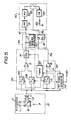
- an optical system 10 irradiates a laser beam P generated by a laser beam generator (not shown) onto the recording surface of an optical disc D which may be a recordable optical disc such as an optomagnetic disc, via a beam splitter B and an objective lens L1.
- the laser beam P is reflected and received by a light receiving element 11 via the beam splitter B and a convergence lens L2.
- the light receiving element 11 and the convergence lens L2 are arranged in alignment with each other along which the laser beam P is irradiated onto the disc D.
- the reflected light beam passing the beam splitter B is deflected through about a right angle to be directed towards the light receiving element 11 which produces an electrical signal representative of the data indicated by the reflected light received, which signal is fed to first and second signal processing circuits 20 and 30.
- the first signal processing circuit 20 has first and second sample/hold circuits 12A and 12B which are connected to a timing control circuit 60 which supplies timing control signals for controlling sample/hold timing.
- the timing control circuit 60 supplies a timing control signal at a timing T1 corresponding to the laser beam scanning timing of the servo pit 2A to trigger sampling and holding operation of the first sample hold circuit 12A.
- the timing control circuit 60 supplies a timing control signal at a timing T2 corresponding to the laser beam scanning timing of the servo pit 2B, to trigger sampling and holding operation of the second sample/hold circuit 12B. Therefore, the first and second sample/hold circuits 12a and 12B become active for sampling the signal from the light receiving element 11 at the respective timings T1 and T2.
- the sample/hold circuits 12A and 12B sample the signals representative of the reflected light intensity at the servo pits 2A and 2B, and supply held value indicating output signals.
- the first signal processing circuit 20 includes a subtractor circuit 13 which receives the output signals of both the sample/hold circuits 12A and 12B, and comprises a differential amplifier connected to the sample/hold circuit 12A as its non-inverting input terminal and to the sample/hold circuit 12B at its inverting input terminal.
- the subtractor circuit 13 derives the difference between the output signals of the sample/hold circuits 12A and 12B to supply a difference indicating signal.
- the first signal processing circuit 20 further includes a third sample/hold circuit 14 connected to the timing control circuit 60 to receive therefrom a timing control signal at a timing T3 corresponding to the laser beam scanning timing of the clock pit 3.
- the third sample/hold circuit 14 samples and holds the difference indicating signal in response to the timing control signal at the timing T3.
- the sample/hold circuit 14 supplies the held difference indicating signal as a tracking error signal.
- the second signal processing circuit 30 has a fourth sample/hold circuit 15 which is connected to the timing control circuit 60.
- the fourth sample/hold circuit 15 is also connected to the light receiving element 11 to receive the signal therefrom.
- the fourth sample/hold circuit 15 is responsive to the timing control signal at the timing T3 to be triggered to sample and hold the signal from the light receiving element 11.
- the fourth sample/hold circuit 15 is connected to a comparator circuit 16 which compares the held value indicating output of the sample/hold circuit 15 with zero level.
- the comparator 16 comprises a differential amplifier having a non-inverting input terminal connected to the fourth sample/hold circuit 15, and an inverting input terminal connected to earth.
- the third sample/hold circuit 14 is connected to a tracking servo circuit 50 which comprises a low-pass filter 51, a phase compensation circuit 52, a switching circuit 53, a drive circuit 54 and a tracking coil 55.
- the tracking coil 55 is incorporated in an actuator for driving the objective lens L1 for tracking adjustment.
- the switching circuit 53 is also connected to a D flip-flop 18.
- the third sample/hold circuit 14 is also connected to a zero-crossing detector circuit 17 which detects zero-crossing of the tracking error signal.
- the output of the zero-crossing detector circuit 17 is supplied to the flip-flop 18 which is further connected to the comparator circuit 16 to receive therefrom the comparator signal.
- An RF signal generator 70 receives the output of the light receiving element 11 and reproduces an RF signal.
- the outputs of the light receiving element 11 at the timings T1 and T2 correspond to the reduced reflected light intensity from the servo pits 2A and 2B.
- the output of the light receiving element 11 at the timing T3 is reduced due to irradiation of the clock pit 3.
- the value et of the tracking error signal is variable depending upon the offset of the irradiating position v of the laser beam P.
- the value et of the tracking error signal value varies with radial shifting as shown in Figure 4.
- the tracking error signal value et so derived is supplied from the third sample/hold circuit 14, and the waveform thereof is shown in Figure 6, the waveform being illustrated in analogue form for better understanding.
- the sample/hold value EP of the fourth sample/hold circuit 15 becomes a maximum.
- Extracting the AC component from the sample/hold value EP of the fourth sample/hold circuit 15 is illustrated in analogue waveform as shown in Figure 6.
- the comparator signal is phase-shifted relative to the tracking error signal by ⁇ /2.
- the comparator signal value Pd varies between HIGH level and LOW level. Namely, the comparator signal Pd is held at HIGH level while the sample/hold value EP is above zero level, and is held at LOW level while the sample/hold value EP is below zero level.
- the comparator signal Pd is supplied to the flip-flop 18 via its D-terminal, while the tracking error signal is supplied to the zero-crossing detector circuit 17.
- the zero-crossing detector circuit 17 detects the zero value of the tracking error signal to generate a trigger pulse Pt which is supplied to the flip-flop 18 to reverse the set/reset conditions thereof. Therefore, the output SG of the flip-flop, as shown in Figure 6, can be obtained.
- the polarity of the output signal SG of the flip-flop 18 varies depending upon the relative shift direction between the laser beam irradiating point v and the recording tracks on the disc D. Namely, the output signal SG is held at HIGH level only in a period between the timings t1 and t2, in which the laser beam irradiating point v shifts across the track centre, when the laser beam irradiating point shifts in a direction +v.
- the output signal SG is held at LOW level during a period between the timings t2 and t3, in which the irradiating point v of the laser beam shifts across the intermediate point between the adjacent tracks, when the laser beam irradiating point shifts in a direction +v.
- the output signal SG is held at HIGH level only in a period between the timing t3 and t2, in which the laser beam irradiating point v shifts across the track centre, and is held at LOW level during a period between the timings t2 and t1, in which the irradiating point v of the laser beam shifts across the intermediate point between the adjacent tracks.
- the output signal Sg of the flip-flop 18 is fed to the switching circuit 53 of the tracking servo circuit 50 to open and close it.
- the switching circuit 53 is responsive to the HIGH level output signal Sg of the flip-flop 18 to close, and is otherwise held open. Therefore, when the irradiating point of the laser beam shifts in the +v direction, the tracking error signal in a hatched range BR is applied to the tracking coil to perform CLOSED LOOP control to adjust the laser beam irradiating point at the track centre TO.
- the tracking error signal in a hatched range BF is applied to the tracking coil to perform CLOSED LOOP control for decelerating radial shift of the laser beam irradiating point.
Landscapes
- Optical Recording Or Reproduction (AREA)
- Manufacturing Optical Record Carriers (AREA)
- Moving Of The Head For Recording And Reproducing By Optical Means (AREA)
Claims (6)
- Spurfolgesystem für einen optischen Plattenspieler zur Datenwiedergabe und/oder -aufnahme auf einer Vielzahl von koaxial ausgebildeten Spuren auf einer optischen Platte (D), welche ein Paar von Servopits (2A, 2B) und ein Taktpit (3) auf jeder der genannten Aufnahmespuren aufweist, wobei das Paar von Servopits (2A, 2B) auf dem Umfang in einem bekannten Abstand voneinander angeordnet ist und radial um eine bekannte Distanz jeweils in entgegengesetzten Richtungen von der Spurmittellinie versetzt ist, wobei das System umfaßt:
einen Laserstrahlgenerator (10) zum Ausstrahlen eines Laserstrahls (P) auf die genannte Platte zum Abtasten der Aufnahmespuren,
Ansteuermittel (55) für den Laserstrahl zum Erzeugen einer Verschiebung des von dem genannten Laserstrahl (P) bestrahlten Punktes in radialer Richtung,
eine Spurfolgeschaltung (50) zum Steuern der genannten Ansteuermittel (55) für den Laserstrahl, wobei die genannte Spurfolgeschaltung geeignet ist, die genannten Ansteuermittel (55) für den Laserstrahl derart zu betreiben, eine radiale Verschiebung des von dem genannten Laserstrahl bestrahlten Punktes zu veranlassen, und weiterhin geeignet ist, in der Art einer Rückführung den durch den genannten Laserstrahl bestrahlten Punkt im Verhältnis zu der genannten Spurmittellinie einzurichten,
Lichtempfangsmittel (11) zum Empfang des von dem vom Laserstrahl bestrahlten Punkt reflektierten Lichtstrahls und zum Erzeugen eines die Lichtintensität anzeigendes Signal,
erste Mittel (20) zur Signalverarbeitung zum Empfang der genannten die Lichtintensität anzeigenden Signale, welche jeweils repräsentativ für die Lichtintensität des von den jeweiligen Servopits (2A, 2B) reflektierten Lichtstrahls sind, und zur Herleitung eines Spurfolgefehlersignals auf Grundlage der Werte der die Lichtintensität anzeigenden Signale, und
zweite Mittel (30) zur Signalverarbeitung zum Empfang des genannten die Lichtintensität anzeigenden Signals, welches jeweils repräsentativ für die Lichtintensität des von dem genannten Taktpit (3) reflektierten Lichtstrahls ist, zum Detektieren der Verschiebung des von dem Laserstrahl bestrahlten Punkts in radialer Richtung, und zum Erzeugen eines den Status anzeigenden Signals (Pd), welches die Verschiebung des genannten vom Laserstrahl beleuchteten Punktes in bezug auf die genannte Spurmittellinie anzeigt,
gekennzeichnet durch
dritte Mittel (40) zur Signalverarbeitung zum Empfang des genannten Spurfolgefehlersignals, um den Nulldurchgang des Wertes des Spurfolgefehlersignals zur Erzeugung eines einen Nulldurchgang anzeigenden Signals (Pt) festzustellen, und zum Herleiten eines Servosteuersignals (SG) zum Freigeben und Sperren der genannten im Rückkopplungsmodus arbeitenden Spurfolgesteuerung der genannten Spurfolgeschaltung (50) auf Grundlage des genannten den Status anzeigenden Signals und des genannten den Nulldurchgang anzeigenden Signals, wobei der genannte Rüchkopplungsmodus freigegeben wird, wenn ein Nulldurchgang angezeigt wird und der genannte Laserstrahl sich innerhalb eines vorgegebenen radialen Abstands von der genannten Spurmittellinie befindet, und gesperrt wird, wenn ein Nulldurchgang angezeigt wird und der Laserstrahl sich nicht innerhalb des genannten vorgegebenen radialen Abstands von der genannten Spurmittellinie befindet. - System nach Anspruch 1, bei dem die genannten dritten Mittel (40) zur Signalverarbeitung ein D-Flipflop enthalten, das einen D-Eingangsanschluß zum Empfang des genannten den Status anzeigenden Signals (Pd) und einen Lösch-Eingangsanschluß zum Empfang des genannten einen Nulldurchgang anzeigenden Signals (Pt) besitzt, sowie einen Ausgangsanschluß zur Abgabe des genannten Servosteuersignals (SG).
- System nach Anspruch 1, in welchem die genannte Spurfolgeschaltung (50) zum Steuern der genannte Ansteuerungsmittel (55) für den Laserstrahl im Modus "Geschlossener Regelkreis" und im Modus "Offener Regelkreis" betrieben werden kann, wobei die genannten Spurfolgeschaltungen (50) geeignet ist, die genannten Ansteurermittel (55) für den Laserstrahl derart zu betreiben, um eine radiale Verschiebung des genannten von dem Laserstrahl bestrahlten Punktes zu bewirken und um den genannten von dem Laserstrahl bestrahlten Punkt bezüglich der genannten Spurmittellinie in dem genannten Modus "Geschlossener Regelkreis" zu justieren, und in welchem die genannten dritten Mittel (40) zur Signalverarbeitung selektiv die genannten Spurfolgeschaltungen (50) im genannten Modus "Geschlossener Regelkreis" und im genannten Modus "Offener Regelkreis" auf Grundlage des genannten den Status anzeigenden Signals und des genannten einen Nulldurchgang anzeigenden Signals betreiben.
- System nach Anspruch 3, in welchem die genannten ersten Mittel (20) zur Signalverarbeitung erste Mittel (12A) zum Abtasten des genannten die Lichtintensität anzeigenden Signals zu einem ersten bekannten Zeitpunkt, an welchem der genannte Laserstrahl (P) auf ein erstes Servopit (2A) des genannten Paars ausgestrahlt wird, zweite Mittel (12B) zum Abtasten des genannten die Lichtintensität anzeigenden Signals zu einem zweiten bekannten Zeitpunkt, an welchem der genannte Laserstrahl (P) auf ein zweites Servopit (2B) des genannten Paars ausgestrahlt wird, und dritte Mittel (13, 14) zur Herleitung einer Differenz zwischen den genannten die Lichtintensität anzeigenden Signalen, die durch die genannten ertsten und zweiten Mittel (12A, 12B) abgetastet worden sind, zum Herleiten des genannten Spurfolge-Fehlersignals, enthalten.
- System nach Anspruch 4, in welchem die genannten zweiten Mittel (30) zur Signalverarbeitung vierte Mittel (15) zum Abtasten des genannten die Lichtintensivität anzeigenden Signals zu einem dritten bekannten Zeitpunkt, an welchem der genannte Laserstrahl auf das genannte Taktpit (3) ausgestrahlt wird, enthalten, um das genannte den Status anzeigende Signal zu erzeugen, das eine Phasenverschiebung von bekannter Größe hinsichtlich des genannten Spurfolgefehlersignals aufweist.
- System nach Anspruch 5, in welchem die genannte Phasenverschiebung π/2 beträgt.
Priority Applications (1)
| Application Number | Priority Date | Filing Date | Title |
|---|---|---|---|
| AT87311056T ATE86043T1 (de) | 1986-12-15 | 1987-12-15 | Spurfolgesysteme fuer optische plattenspieler. |
Applications Claiming Priority (2)
| Application Number | Priority Date | Filing Date | Title |
|---|---|---|---|
| JP296644/86 | 1986-12-15 | ||
| JP61296644A JPH0679378B2 (ja) | 1986-12-15 | 1986-12-15 | 光学式記録再生装置のトラツキングサ−ボ回路 |
Publications (3)
| Publication Number | Publication Date |
|---|---|
| EP0272873A2 EP0272873A2 (de) | 1988-06-29 |
| EP0272873A3 EP0272873A3 (en) | 1989-10-04 |
| EP0272873B1 true EP0272873B1 (de) | 1993-02-24 |
Family
ID=17836205
Family Applications (1)
| Application Number | Title | Priority Date | Filing Date |
|---|---|---|---|
| EP87311056A Expired - Lifetime EP0272873B1 (de) | 1986-12-15 | 1987-12-15 | Spurfolgesysteme für optische Plattenspieler |
Country Status (6)
| Country | Link |
|---|---|
| US (1) | US4843601A (de) |
| EP (1) | EP0272873B1 (de) |
| JP (1) | JPH0679378B2 (de) |
| KR (1) | KR950007290B1 (de) |
| AT (1) | ATE86043T1 (de) |
| DE (1) | DE3784326T2 (de) |
Cited By (1)
| Publication number | Priority date | Publication date | Assignee | Title |
|---|---|---|---|---|
| DE19900717C5 (de) * | 1998-01-13 | 2008-06-19 | Fujitsu Ltd., Kawasaki | Optisches Speichergerät |
Families Citing this family (22)
| Publication number | Priority date | Publication date | Assignee | Title |
|---|---|---|---|---|
| JPS6437773A (en) * | 1987-08-01 | 1989-02-08 | Sony Corp | Track jump device of disk device |
| US5184338A (en) * | 1987-06-25 | 1993-02-02 | Mitsubishi Denki Kabushiki Kaisha | Optical disc system with improved track jumping operation |
| DE3732899A1 (de) * | 1987-09-30 | 1989-04-20 | Thomson Brandt Gmbh | Spurregelkreis fuer eine optische abtastvorrichtung |
| JPH073692B2 (ja) * | 1987-12-02 | 1995-01-18 | 株式会社日立製作所 | 光ディスク装置におけるトラッキング制御回路 |
| US5321675A (en) * | 1988-03-03 | 1994-06-14 | Mitsubishi Denki Kabushiki Kaisha | Pit spacing in the servo field of an optical disk for speed and direction detection and data retrieval |
| JPH02149932A (ja) * | 1988-11-30 | 1990-06-08 | Victor Co Of Japan Ltd | 光ディスク読取装置 |
| JP2785290B2 (ja) * | 1988-12-19 | 1998-08-13 | ソニー株式会社 | 光ディスクのシーク及びトラッキング装置 |
| US5253239A (en) * | 1989-11-24 | 1993-10-12 | Matsushita Electric Industrial Co., Ltd. | Control apparatus for tracking a light beam on a track of an optical recording medium |
| US5214629A (en) * | 1990-02-27 | 1993-05-25 | Hitachi Maxell, Ltd. | Optical disc having a high-speed access capability and reading apparatus therefor |
| JP2836756B2 (ja) * | 1990-04-19 | 1998-12-14 | オリンパス光学工業株式会社 | 光学的情報記録・再生装置のトラックジャンプ制御装置 |
| US5268887A (en) * | 1990-05-15 | 1993-12-07 | Kabushiki Kaisha Toshiba | Optical recording medium having offset-compensating areas |
| JPH0478034A (ja) * | 1990-05-15 | 1992-03-12 | Toshiba Corp | 光情報記録媒体及び光情報記録再生装置 |
| JP2656371B2 (ja) * | 1990-06-26 | 1997-09-24 | 富士通株式会社 | 光ディスク装置 |
| JPH04236589A (ja) * | 1991-01-18 | 1992-08-25 | Fujitsu Ltd | データ処理装置 |
| JPH04259921A (ja) * | 1991-02-15 | 1992-09-16 | Ricoh Co Ltd | 光ディスク装置 |
| TW213519B (de) * | 1991-08-01 | 1993-09-21 | Philips Nv | |
| EP0562595A3 (en) * | 1992-03-26 | 1994-07-06 | Matsushita Electric Industrial Co Ltd | Apparatus for positioning optical head on a track of rotating disk |
| JPH0696524A (ja) * | 1992-09-11 | 1994-04-08 | Sony Corp | 記録媒体、記録方法、記録再生装置およびカッティング装置 |
| JPH08306054A (ja) * | 1995-04-28 | 1996-11-22 | Sony Corp | トラッキングサーボ回路 |
| US20060149369A1 (en) * | 1997-05-20 | 2006-07-06 | C&C Vision International Limited | Accommodating arching lens |
| DE10064050A1 (de) * | 2000-12-21 | 2002-07-04 | Thomson Brandt Gmbh | Verfahren zu Positionssteuerung bei optischen Datenträgern mit Adressinformationen |
| WO2006003544A1 (en) * | 2004-06-28 | 2006-01-12 | Koninklijke Philips Electronics N.V. | A method for improving robustness of optical disk readout |
Family Cites Families (15)
| Publication number | Priority date | Publication date | Assignee | Title |
|---|---|---|---|---|
| AU530869B2 (en) * | 1979-09-26 | 1983-08-04 | Discovision Associates | Video disc player |
| JPS5774837A (en) * | 1980-10-25 | 1982-05-11 | Olympus Optical Co Ltd | Signal detection system of optical information reproducing device |
| DE3111113C2 (de) * | 1981-03-20 | 1986-01-23 | Karl Mayer Textil-Maschinen-Fabrik Gmbh, 6053 Obertshausen | Regelvorrichtung für den Motor einer das Gewirk beeinflussenden Wickelvorrichtung, wie Teilkettbaum, bei einer Kettenwirkmaschine |
| US4494226A (en) * | 1981-10-15 | 1985-01-15 | Burroughs Corporation | Three beam optical memory system |
| JPS5877036A (ja) * | 1981-10-30 | 1983-05-10 | Olympus Optical Co Ltd | ピット中心検出方法 |
| US4564929A (en) * | 1981-11-25 | 1986-01-14 | Hitachi, Ltd. | Information recording and reproducing apparatus with tracking control by sampling |
| JPS58143472A (ja) * | 1982-02-22 | 1983-08-26 | Hitachi Ltd | 記録情報再生装置のトラツキングサ−ボ制御装置 |
| FR2523349A1 (fr) * | 1982-03-12 | 1983-09-16 | Thomson Csf | Procede et dispositif optique de generation de signaux d'asservissements de la position d'une tache d'exploration des pistes d'un support d'information |
| FR2523347B1 (fr) * | 1982-03-12 | 1988-11-04 | Thomson Csf | Support d'information mobile pregrave et dispositif optique de suivi de piste mettant en oeuvre un tel support |
| JPS592240A (ja) * | 1982-06-25 | 1984-01-07 | Pioneer Electronic Corp | トラツキングサ−ボ装置 |
| JPS59167861A (ja) * | 1983-03-14 | 1984-09-21 | Sony Corp | 光学式デイスク・プレ−ヤ−のトラツキング制御装置 |
| JPS61977A (ja) * | 1984-06-13 | 1986-01-06 | Pioneer Electronic Corp | トラツキングサ−ボ装置 |
| US4748609A (en) * | 1985-03-29 | 1988-05-31 | Hitachi, Ltd. | Method and apparatus for composite tracking servo system with track offset correction and rotary optical disc having at least one correction mark for correcting track offset |
| US4740939A (en) * | 1985-05-22 | 1988-04-26 | Hitachi Ltd. | Apparatus for reproducing information recorded on a disk |
| US4779251A (en) * | 1987-06-12 | 1988-10-18 | Optimem | Optical disk memory system with closed loop micro-jump between adjacent tracks |
-
1986
- 1986-12-15 JP JP61296644A patent/JPH0679378B2/ja not_active Expired - Fee Related
-
1987
- 1987-12-11 US US07/131,574 patent/US4843601A/en not_active Expired - Lifetime
- 1987-12-15 DE DE8787311056T patent/DE3784326T2/de not_active Expired - Fee Related
- 1987-12-15 AT AT87311056T patent/ATE86043T1/de not_active IP Right Cessation
- 1987-12-15 KR KR1019870014312A patent/KR950007290B1/ko not_active Expired - Fee Related
- 1987-12-15 EP EP87311056A patent/EP0272873B1/de not_active Expired - Lifetime
Cited By (1)
| Publication number | Priority date | Publication date | Assignee | Title |
|---|---|---|---|---|
| DE19900717C5 (de) * | 1998-01-13 | 2008-06-19 | Fujitsu Ltd., Kawasaki | Optisches Speichergerät |
Also Published As
| Publication number | Publication date |
|---|---|
| EP0272873A3 (en) | 1989-10-04 |
| EP0272873A2 (de) | 1988-06-29 |
| KR950007290B1 (ko) | 1995-07-07 |
| DE3784326D1 (de) | 1993-04-01 |
| JPH0679378B2 (ja) | 1994-10-05 |
| KR880008257A (ko) | 1988-08-30 |
| US4843601A (en) | 1989-06-27 |
| ATE86043T1 (de) | 1993-03-15 |
| DE3784326T2 (de) | 1993-07-29 |
| JPS63149835A (ja) | 1988-06-22 |
Similar Documents
| Publication | Publication Date | Title |
|---|---|---|
| EP0272873B1 (de) | Spurfolgesysteme für optische Plattenspieler | |
| KR100324848B1 (ko) | 광재생장치 | |
| US5084860A (en) | Apparatus for optical disc memory with correction pattern and master disc cutting apparatus | |
| US4751695A (en) | Method and apparatus for tracking servo system | |
| JPH0227734B2 (de) | ||
| KR100245544B1 (ko) | 방사 감응층을 갖는 기록 매체 상에 정보를 기록하기 위한 장치 | |
| US4803677A (en) | Rotary recording medium having a guide track and recording and reproducing apparatus therefor | |
| JPH06243496A (ja) | ディスク再生装置及びそのフォーカスバランス自動調整方法及び信号処理装置 | |
| JPH05242495A (ja) | 光ディスク装置のフォーカス制御機構 | |
| US5621709A (en) | Tracking servo apparatus | |
| US5142518A (en) | Gain control system for error signal amplifier in tracking servo apparatus | |
| EP0345352A1 (de) | Spursprunggerät für speicherplattengerät | |
| US5121375A (en) | Information-recorded disk carrying tracking pilot signal and playing apparatus therefor | |
| HK183296A (en) | Data reproduction device | |
| JP2528822B2 (ja) | 情報記録媒体およびその記録再生装置 | |
| JP2693608B2 (ja) | 情報記録ディスク演奏装置 | |
| JP2576217B2 (ja) | 光ディスク装置のトラッキング制御装置 | |
| JP2912981B2 (ja) | 光学情報記録再生装置 | |
| EP1079374A2 (de) | Gerät zur Aufzeichnung/Wiedergabe eines Signals auf/von einer optischen Platte | |
| JPH0721588A (ja) | 光記録媒体及び光記録媒体の再生装置 | |
| JP2001093172A (ja) | 光ディスク装置 | |
| JPH0684185A (ja) | 光ディスク装置 | |
| JP2570915B2 (ja) | 光スポット制御方法 | |
| JPH073701B2 (ja) | 光学式記録再生装置のトラツキングサ−ボ回路 | |
| JPH05234110A (ja) | フォーカスオフセット自動調整装置 |
Legal Events
| Date | Code | Title | Description |
|---|---|---|---|
| PUAI | Public reference made under article 153(3) epc to a published international application that has entered the european phase |
Free format text: ORIGINAL CODE: 0009012 |
|
| AK | Designated contracting states |
Kind code of ref document: A2 Designated state(s): AT DE FR GB IT NL |
|
| PUAL | Search report despatched |
Free format text: ORIGINAL CODE: 0009013 |
|
| AK | Designated contracting states |
Kind code of ref document: A3 Designated state(s): AT DE FR GB IT NL |
|
| RHK1 | Main classification (correction) |
Ipc: G11B 7/08 |
|
| 17P | Request for examination filed |
Effective date: 19900202 |
|
| 17Q | First examination report despatched |
Effective date: 19910614 |
|
| GRAA | (expected) grant |
Free format text: ORIGINAL CODE: 0009210 |
|
| AK | Designated contracting states |
Kind code of ref document: B1 Designated state(s): AT DE FR GB IT NL |
|
| REF | Corresponds to: |
Ref document number: 86043 Country of ref document: AT Date of ref document: 19930315 Kind code of ref document: T |
|
| REF | Corresponds to: |
Ref document number: 3784326 Country of ref document: DE Date of ref document: 19930401 |
|
| ITF | It: translation for a ep patent filed | ||
| ET | Fr: translation filed | ||
| PLBE | No opposition filed within time limit |
Free format text: ORIGINAL CODE: 0009261 |
|
| STAA | Information on the status of an ep patent application or granted ep patent |
Free format text: STATUS: NO OPPOSITION FILED WITHIN TIME LIMIT |
|
| 26N | No opposition filed | ||
| ITTA | It: last paid annual fee | ||
| PGFP | Annual fee paid to national office [announced via postgrant information from national office to epo] |
Ref country code: FR Payment date: 20011212 Year of fee payment: 15 Ref country code: AT Payment date: 20011212 Year of fee payment: 15 |
|
| PGFP | Annual fee paid to national office [announced via postgrant information from national office to epo] |
Ref country code: GB Payment date: 20011219 Year of fee payment: 15 |
|
| PGFP | Annual fee paid to national office [announced via postgrant information from national office to epo] |
Ref country code: NL Payment date: 20011228 Year of fee payment: 15 |
|
| REG | Reference to a national code |
Ref country code: GB Ref legal event code: IF02 |
|
| PGFP | Annual fee paid to national office [announced via postgrant information from national office to epo] |
Ref country code: DE Payment date: 20020109 Year of fee payment: 15 |
|
| PG25 | Lapsed in a contracting state [announced via postgrant information from national office to epo] |
Ref country code: GB Free format text: LAPSE BECAUSE OF NON-PAYMENT OF DUE FEES Effective date: 20021215 Ref country code: AT Free format text: LAPSE BECAUSE OF NON-PAYMENT OF DUE FEES Effective date: 20021215 |
|
| PG25 | Lapsed in a contracting state [announced via postgrant information from national office to epo] |
Ref country code: NL Free format text: LAPSE BECAUSE OF NON-PAYMENT OF DUE FEES Effective date: 20030701 Ref country code: DE Free format text: LAPSE BECAUSE OF NON-PAYMENT OF DUE FEES Effective date: 20030701 |
|
| GBPC | Gb: european patent ceased through non-payment of renewal fee |
Effective date: 20021215 |
|
| NLV4 | Nl: lapsed or anulled due to non-payment of the annual fee |
Effective date: 20030701 |
|
| PG25 | Lapsed in a contracting state [announced via postgrant information from national office to epo] |
Ref country code: FR Free format text: LAPSE BECAUSE OF NON-PAYMENT OF DUE FEES Effective date: 20030901 |
|
| REG | Reference to a national code |
Ref country code: FR Ref legal event code: ST |
|
| PG25 | Lapsed in a contracting state [announced via postgrant information from national office to epo] |
Ref country code: IT Free format text: LAPSE BECAUSE OF NON-PAYMENT OF DUE FEES;WARNING: LAPSES OF ITALIAN PATENTS WITH EFFECTIVE DATE BEFORE 2007 MAY HAVE OCCURRED AT ANY TIME BEFORE 2007. THE CORRECT EFFECTIVE DATE MAY BE DIFFERENT FROM THE ONE RECORDED. Effective date: 20051215 |