EP0272736A1 - Device for reducing the quantity of oxygen in the space above the filling in a container - Google Patents
Device for reducing the quantity of oxygen in the space above the filling in a container Download PDFInfo
- Publication number
- EP0272736A1 EP0272736A1 EP87202418A EP87202418A EP0272736A1 EP 0272736 A1 EP0272736 A1 EP 0272736A1 EP 87202418 A EP87202418 A EP 87202418A EP 87202418 A EP87202418 A EP 87202418A EP 0272736 A1 EP0272736 A1 EP 0272736A1
- Authority
- EP
- European Patent Office
- Prior art keywords
- container
- space
- chamber
- vacuum
- source
- Prior art date
- Legal status (The legal status is an assumption and is not a legal conclusion. Google has not performed a legal analysis and makes no representation as to the accuracy of the status listed.)
- Withdrawn
Links
Images
Classifications
-
- B—PERFORMING OPERATIONS; TRANSPORTING
- B65—CONVEYING; PACKING; STORING; HANDLING THIN OR FILAMENTARY MATERIAL
- B65B—MACHINES, APPARATUS OR DEVICES FOR, OR METHODS OF, PACKAGING ARTICLES OR MATERIALS; UNPACKING
- B65B31/00—Packaging articles or materials under special atmospheric or gaseous conditions; Adding propellants to aerosol containers
- B65B31/04—Evacuating, pressurising or gasifying filled containers or wrappers by means of nozzles through which air or other gas, e.g. an inert gas, is withdrawn or supplied
- B65B31/046—Evacuating, pressurising or gasifying filled containers or wrappers by means of nozzles through which air or other gas, e.g. an inert gas, is withdrawn or supplied the nozzles co-operating, or being combined, with a device for opening or closing the container or wrapper
-
- B—PERFORMING OPERATIONS; TRANSPORTING
- B67—OPENING, CLOSING OR CLEANING BOTTLES, JARS OR SIMILAR CONTAINERS; LIQUID HANDLING
- B67B—APPLYING CLOSURE MEMBERS TO BOTTLES JARS, OR SIMILAR CONTAINERS; OPENING CLOSED CONTAINERS
- B67B3/00—Closing bottles, jars or similar containers by applying caps
- B67B3/24—Special measures for applying and securing caps under vacuum
Definitions
- the invention relates to a process for reducing the quantity of oxygen in the space above the filling in a container before closing of the container, in which a vacuum is formed in said space, then a compressed gas which is inert for the contents of the container is blown into the container and again a vacuum is formed in said space, these steps being repeated if necessary.
- the invention also relates to a device for carrying out the process comprising a number of sealing heads mounted in the form of a caroussel on a vertical central column which is driven so that it rotates, each of said heads being able to engage in sealing fashion the top of a container provided with a filling opening, so that the filling opening comes to be situated in a space within the sealing head sealed off from the outside air, it being possible to place said space in connection with a source of vacuum and operable valve means for alternately putting into communication said space with a vacuum source and a source of a chemical inert gas.
- the valve means are formed by two valves by means of which said space can be put into communication with either a source of an inert gas or with only one vacuum source, said valves comprising each a valve disc connected to a valve rod which disc operates with an annular valve seat.
- a third valve of this type is provided by means of which said space can be put into communication with the outside air in order to be able to remove the container from said space after the container being closed.
- a device for the evacuation and sealing of containers in which a nozzle is inserted into the container and the sidewalls of the container are pressed against the nozzle to form a substantially air tight seal there between.
- the nozzle is connected through a conduit with a passageway bored in a ring which is adapted to rotate together with said nozzle, which passageway opens at a face of said ring which is in engagement with a face of a stationary plate in which a plurality of recesses are formed which during the rotational movement of the ring becomes aligned successively with the opening of said passageway, each recess in the stationary plate being into communication through said plate with a separate conduit which is connected with a source of an inert gas and a vacuum source respectively.
- the object of the invention is to provide an improved process and device by which the quantity of oxygen in the space above the filling of a container can be decreased to less than 0,5 %.
- a final vacuum is created in the space as a last step, during which step the quantity of oxygen in the container is, of course, again reduced, the final vacuum being of a depth which differs from that of the previous vacuums.
- the nozzle which can be placed in connection with a source of a chemically inert gas opens in the space inside the sealing head in such a way that it is possible to produce a jet of the said gas flowing out of said nozzle and directed towards the filling opening of a container in a direction extending obliquely to the vertical axis of the container, the device further comprising a fixed, essentially enclosed housing within which are formed, coaxially with the central column, an inner chamber and an outer, essentially cylindrical chamber enclosing it, one of these chambers being connected to the vacuum source and the other chamber to the source of a chemically inert gas, while in one head face of each chamber provision is made for a number of openings at specific angular distances from each other and disposed on an inner and an outer circle respectively, while fixed on the central rotating column is a disc which rests in sealing fashion against said head faces, and in which two series of openings with equal angular distances from each other are formed on an inner
- each container is subjected at the right moments to the successive steps of creation of a vacuum and blowing in of a chemically inert gas, whereas in that the connections between the respective sealing heads and the vacuum and gas sources respectively are separated from each other there is no risk that said sources are short-circuited.
- the device according to the invention is extremely well adopted to be cleaned in accordance with the required c.i.p.-s.i.p. principle (clean in place, sterilize in place).
- the openings in the said head faces of the chambers, at least the part facing the disc are in the shape of a circular arc-shaped groove, which means that the times during which the containers are subjected to the various steps can be adapted to in particular the volume of the space above the filling in the containers.
- the sealing heads are each provided with a suction head to be connected to a vacuum source for taking into the said space a closing cap or cover for the container whereas, once the vacuum is created in the said space within the sealing head the cap would fall from the suction head, provision is made for a catch mechanism in each sealing head to retain the closing cap, because this cap must not block the filling opening of a container before the final gas-inblowing step has been carried out.
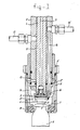
- the device comprises a number of sealing heads, one of which is shown in fig. 1, and which are mounted, standing upright, at equal angular intervals in a circle, in a manner not illustrated in greater detail, on the vertical central column 1 (see fig. 2).
- Each sealing head has a relatively thick-walled length of tubing 2, which at the top end, for an up and dowm movement, is guided in a curved track (not shown), and within which a rod 4 provided with a central channel 3 can slide up and down. Disposed on the rod 4 at the bottom end is a suction head 5, so that by connecting the channel 3, in a manner not further illustrated, to a vacuum source, a closing cap 6 for a container can be sucked fast on the suction cap 5, while the rod 4 is in the bottom position not shown, and if the rod 4 is then raised to the position shown, this cap 6 can be taken inside the space 7 of the sealing head.
- This space 7 is enclosed by a sealing sleeve 8 which is connected to a slide piece 8 ⁇ which is under a downward-directed spring pressure (not shown), and which can slide along the tube 2, permitting the sealing sleeve 8 to move up and down between a bottom position which is not shown and the top position which is shown.
- the sealing sleeve encloses the top of the container 9, while the sealing ring 10 disposed at the end of the sealing sleeve engages in sealing fashion with the container 9, so that the space 7 is sealed off relative to the environment.
- annular channel 11 Formed between the length of tubing 2 and the rod 3 is an annular channel 11, which is connected at one end to a connection piece 12 which can be connected to at least one vacuum source, and at the other end opens into a set of radial channels 13 which in the highest position of the sealing sleeve 8 are connected to the top part 14 of the space 7, so that when the connection 12 is open to the vacuum source a vacuum is created in the container 9.
- the sealing sleeve 8 belonging to it will remain in the lowest position, which means that the connection between the channels 13 and the part 14 is closed through the fact that the bottom inside edge of the slide piece 8 ⁇ has engaged with the sealing ring 8 ⁇ .
- connection piece 15 ⁇ which can be connected to a source for a pressurized chemically inert gas, for example nitrogen, and at the other end merges into a nozzle 16 which opens into the space 7, in such a way that when the said gas flows through the channel 15, a gas jet is blown into the container 9, being directed in the direction of the arrow A obliquely towards the container 9.
- a pressurized chemically inert gas for example nitrogen
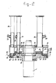
- the control mechanism of the device comprises an essentially closed housing which is formed by a sleeve 18 which is mounted by means of rolling bearings so that it rotates about the column 1, a top disc 19 fixed to this sleeve, a peripheral wall 20, and an inner 21 and an outer annular disc 22, which are separated from each other by a partition wall 23, by means of which the inside of the closed housing is also divided into two annular chambers 24 and 25.
- the outer annular chamber 25 is connected by means of the connecting piece 26 having the measuring point 27 to a source of a chemically inert compressed gas, for example nitrogen, while the inner annular chamber 24 is connected by means of the connecting piece 28 having the measuring point 29 to a first vacuum source.
- a length of tubing 30 Passed through the inner annular chamber 25 is a length of tubing 30, which at its top end is connected to the connecting piece 31 with measuring point 32, which is connected to a second vacuum source. At the bottom end the length of tubing 30 is accommodated in an opening in the inner annular disc 21.
- rings 21 and 22 are provided with rings 21 ⁇ and 22 ⁇ made of Teflon or a similar material.
- rings 21 ⁇ and 22 ⁇ made of Teflon or a similar material.
- rings 21, 21 ⁇ and 22, 22 ⁇ respectively by one single ring made of a plastic material e.g. Deldrin
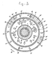
- openings 33, 34, 35 are provided in the inner disc 21 .
- openings 33, 34, 35 which at their bottom ends open into oblong openings 33 ⁇ , 34 ⁇ , and 35 ⁇ , which are provided in the Teflon layer 21 ⁇ .
- the bottom end of the length of tubing 30 is accommodated in the opening 35.
- Drilled in the outer disc 22 are a number of openings 36, 36 ⁇ ; 37, 37 ⁇ ; 38 of which the openings 36 and 36 ⁇ open into an oblong opening 36 ⁇ which is disposed in the Teflon layer 22 ⁇ , the openings 37 and 37 ⁇ open into an oblong opening 37 ⁇ disposed in the Teflon layer 22 ⁇ , and the opening 38 opens into the oblong opening 38 ⁇ disposed in the Teflon layer 22 ⁇ .
- a disc 39 is fixed to the column 1 in such a way that the top faces of this disc rest in sealing fashion against the annular Teflon layers 21 ⁇ and 22 ⁇ . Disposed in this disc 39 are a number of openings 40 Vietnamese distance from each other, and each being connected by means of pipes (not shown) to the connecting piece 15 ⁇ of a respective sealing head. Provision is also made in the disc 39 for a number of openings 50 etc59 laying on an inner circle at equal angular distances from each other, and each being connected by means of a pipe (not shown) to the connecting piece 12 of a respective sealing head, while the pairs of openings 40, 50; 41, 51; Vietnamese 49, 59 belong to one and the same sealing head.
- the opening 50 will first coincide with the opening 33, 33 ⁇ , as a result of which the connection 12 of the particular sealing head and thereby the space 7 thereof is connected to the first vacuum source, so that a vacuum will be created in the container 9.
- the opening 40 will subsequently coincide with the opening 36 ⁇ , as shown in fig.
- connection 15 ⁇ of the sealing head is connected to the source of a compressed gas, so that a gas jet A will be blown out of the nozzle 16 into the container 9 while, since the opening 50 has reached the position indicated by 51, the connection to the vacuum source is interrupted.
- the opening 50 will, however, be brought to coincide with the oblong opening 34 ⁇ , again creating a vacuum in the container 9, while the connection to the source of a compressed gas is broken, due to the fact that the opening 40 will have reached the position indicated by 42.
- This opening 40 will subsequently coincide with the oblong opening 37 ⁇ , again causing a gas jet to flow out of the nozzle 16, while the connection with the vacuum source is interrupted again, due to the fact that the relevant opening 50 has reached the position indicated by 54. Since thereafter this opening 50 will reach the position indicated by 55, a connection via the length of tubing 30 between the second vacuum source and the space 7 is formed, thereby creating a final vacuum in the container 9.
- the closing cap 6 is pressed into the filling opening of the container by means of the rod 4, following which the container 9 is ready.
- Fig. 3 also shows the openings 60 and 61, which serve to fix retaining rods for the housing 18, 19, 20, 21, 22.
Applications Claiming Priority (2)
| Application Number | Priority Date | Filing Date | Title |
|---|---|---|---|
| NL8603176 | 1986-12-12 | ||
| NL8603176A NL8603176A (nl) | 1986-12-12 | 1986-12-12 | Werkwijze en inrichting voor het verlagen van de hoeveelheid zuurstof in de ruimte boven de vulling binnen een houder. |
Publications (1)
| Publication Number | Publication Date |
|---|---|
| EP0272736A1 true EP0272736A1 (en) | 1988-06-29 |
Family
ID=19848996
Family Applications (1)
| Application Number | Title | Priority Date | Filing Date |
|---|---|---|---|
| EP87202418A Withdrawn EP0272736A1 (en) | 1986-12-12 | 1987-12-04 | Device for reducing the quantity of oxygen in the space above the filling in a container |
Country Status (3)
| Country | Link |
|---|---|
| US (1) | US4848419A (nl) |
| EP (1) | EP0272736A1 (nl) |
| NL (1) | NL8603176A (nl) |
Cited By (6)
| Publication number | Priority date | Publication date | Assignee | Title |
|---|---|---|---|---|
| EP0622301A1 (de) * | 1993-04-29 | 1994-11-02 | Rudolf Christoph Bilz | Evakuiervorrichtung |
| WO2008077446A1 (de) * | 2006-12-23 | 2008-07-03 | Khs Ag | VERFAHREN ZUM VERSCHLIEßEN VON BEHÄLTERN SOWIE VERSCHLIEßMASCHINE |
| ITBO20110260A1 (it) * | 2011-05-11 | 2012-11-12 | Pietro Dovesi | Dispositivo di tappatura e di aspirazione |
| WO2019194810A1 (en) * | 2018-04-05 | 2019-10-10 | Norik Kagramanyan | Apparatuses and methods for container content preservation |
| US10773872B2 (en) | 2016-10-06 | 2020-09-15 | Norik Kagramanyan | Apparatuses and methods for container content preservation |
| US10906791B2 (en) | 2016-10-06 | 2021-02-02 | Norik Kagramanyan | Apparatuses and methods for container content preservation |
Families Citing this family (27)
| Publication number | Priority date | Publication date | Assignee | Title |
|---|---|---|---|---|
| US4959960A (en) * | 1988-10-17 | 1990-10-02 | Automotive Products Plc | Method and apparatus for prefilling hydraulic control apparatus |
| US5201165A (en) * | 1990-10-05 | 1993-04-13 | International Paper Company | Gas displacement device for packaging food and non-food products |
| US5085035A (en) * | 1990-10-05 | 1992-02-04 | International Paper Company | Gas displacement device for packaging food and non-food products |
| US5303835A (en) * | 1992-06-24 | 1994-04-19 | Habley Medical Technology Corporation | Lyophilization cap and method |
| US5419096A (en) * | 1993-07-28 | 1995-05-30 | World Class Packaging Systems, Inc. | Packaging method and apparatus for packaging large meat products in a desired gaseous atmosphere |
| DE4429594A1 (de) * | 1994-08-20 | 1996-02-22 | Khs Masch & Anlagenbau Ag | Verfahren zum Abfüllen eines flüssigen Füllgutes in Flaschen oder dgl. Behälter |
| DE19708864A1 (de) * | 1997-03-05 | 1998-09-10 | Bosch Gmbh Robert | Evakuier- und Verschließeinrichtung für Verschlußstopfen aufweisende Kleinbehälter |
| DE19716846C1 (de) * | 1997-04-22 | 1998-11-19 | Bosch Gmbh Robert | Evakuier- und Verschließvorrichtung |
| NZ527608A (en) * | 1998-06-29 | 2004-09-24 | Astrapak Ltd | Plug and gland aseptic package system |
| US6079461A (en) * | 1998-08-17 | 2000-06-27 | The Heil Co. | Use of inert gas in transfer of comminuted product to tank |
| GB0102386D0 (en) * | 2001-01-31 | 2001-03-14 | Weston Medical Ltd | Method for filling needless injector capsules |
| US7040075B2 (en) * | 2001-08-08 | 2006-05-09 | The Clorox Company | Nitrogen cap chute end |
| ITTO20030229A1 (it) * | 2003-03-27 | 2004-09-28 | Arol Spa | Testa capsulatrice per l'applicazione sotto vuoto di capsule |
| US7219480B2 (en) * | 2003-08-06 | 2007-05-22 | Alcoa Closure Systems International, Inc. | Capping and nitrogen dosing apparatus |
| US20070062162A1 (en) * | 2005-09-19 | 2007-03-22 | Martin Lehmann | Method and apparatus for cleaning containers to be sealed and containing a filler from oxygen gas |
| DE102006061498A1 (de) * | 2006-12-23 | 2008-07-03 | Khs Ag | Verfahren zum Verschließen von Behältern sowie Verschließmaschine |
| DE102007041685A1 (de) * | 2007-09-01 | 2009-03-05 | Krones Ag | Vorrichtung zum Verteilen eines Mediums auf Behältnisse |
| TWI472459B (zh) | 2008-05-19 | 2015-02-11 | Melrose David | 移除真空壓力之頂部空間改性方法及其裝置 |
| FR2933380B1 (fr) * | 2008-07-01 | 2013-01-18 | Airlessystems | Procede de conditionnement de produit fluide dans un distributeur |
| US20110131933A1 (en) * | 2009-11-17 | 2011-06-09 | Livingston Darren D | Pressurized capping apparatus |
| US10266293B1 (en) * | 2014-09-15 | 2019-04-23 | Automated Systems of Tacoma LLC | Method and system for vacuum stoppering of fluid containers |
| RU2590995C1 (ru) * | 2015-04-24 | 2016-07-10 | Общество с ограниченной ответственностью "Эрмайнс" (ООО "Эрмайнс") | Устройство для вакуумирования и укупоривания вакуумных пробирок |
| WO2017218477A1 (en) * | 2016-06-16 | 2017-12-21 | Muffin Incorporated | Vial filling system with localized clean zone |
| MX2019015903A (es) * | 2017-07-11 | 2021-01-29 | Becton Dickinson France | Dispositivo para el sellado de tubo de aireación y de vacío de un contenedor medico. |
| WO2019011961A1 (en) * | 2017-07-11 | 2019-01-17 | Becton Dickinson France | DEVICE FOR VACUUM BLOCKING OF A MEDICAL CONTAINER |
| RU2705818C1 (ru) * | 2018-05-30 | 2019-11-12 | Акционерное общество "КВАРЦ" | Вакуумная камера |
| CN114538345B (zh) * | 2022-04-12 | 2022-09-27 | 河北橡一医药科技股份有限公司 | 一种能提高密封性的医用铝塑盖压合装置 |
Citations (6)
| Publication number | Priority date | Publication date | Assignee | Title |
|---|---|---|---|---|
| NL79806C (nl) * | 1900-01-01 | |||
| US2017766A (en) * | 1928-10-10 | 1935-10-15 | Anchor Cap & Closure Corp | Sealing machine and method |
| US2656963A (en) * | 1947-09-16 | 1953-10-27 | Fmc Corp | Filling machine |
| GB910584A (en) * | 1960-01-12 | 1962-11-14 | R W Barraclough Ltd | Improvements in or relating to apparatus for evacuating and sealing containers |
| FR1426235A (fr) * | 1964-12-03 | 1966-01-28 | Continental Can Co | Tête de capsulage à filtre |
| FR2104100A5 (nl) * | 1970-08-07 | 1972-04-14 | Unilever Nv |
Family Cites Families (9)
| Publication number | Priority date | Publication date | Assignee | Title |
|---|---|---|---|---|
| US1591932A (en) * | 1924-01-11 | 1926-07-06 | American Can Co | Method and apparatus for replacing air in filled containers with inert gas |
| US3350839A (en) * | 1963-07-24 | 1967-11-07 | Kenneth B Ray | Apparatus for packaging fruit juices and similar products |
| US3951186A (en) * | 1974-05-17 | 1976-04-20 | Fmc Corporation | Gas flushing system for beverage filler |
| JPS548078A (en) * | 1977-06-17 | 1979-01-22 | Takeda Chemical Industries Ltd | Device for fitting plug in vial to vacuum |
| US4407340A (en) * | 1980-12-18 | 1983-10-04 | Reynolds Metals Company | Container pressurization system |
| US4489767A (en) * | 1981-09-08 | 1984-12-25 | Toyo Seikan Kaisha, Ltd. | Apparatus for dropping liquefied gases |
| DE3431107A1 (de) * | 1984-08-24 | 1986-03-06 | Krones Ag Hermann Kronseder Maschinenfabrik, 8402 Neutraubling | Verfahren und vorrichtung zum fuellen von flaschen o.dgl. |
| US4662154A (en) * | 1984-10-12 | 1987-05-05 | Continental Can Company, Inc. | Liquid inert gas dispenser and control |
| DE3439736A1 (de) * | 1984-10-31 | 1986-04-30 | Krones Ag Hermann Kronseder Maschinenfabrik, 8402 Neutraubling | Verfahren und vorrichtung zum abfuellen einer fluessigkeit in flaschen o.dgl. |
-
1986
- 1986-12-12 NL NL8603176A patent/NL8603176A/nl not_active Application Discontinuation
-
1987
- 1987-12-04 EP EP87202418A patent/EP0272736A1/en not_active Withdrawn
- 1987-12-09 US US07/130,419 patent/US4848419A/en not_active Expired - Fee Related
Patent Citations (6)
| Publication number | Priority date | Publication date | Assignee | Title |
|---|---|---|---|---|
| NL79806C (nl) * | 1900-01-01 | |||
| US2017766A (en) * | 1928-10-10 | 1935-10-15 | Anchor Cap & Closure Corp | Sealing machine and method |
| US2656963A (en) * | 1947-09-16 | 1953-10-27 | Fmc Corp | Filling machine |
| GB910584A (en) * | 1960-01-12 | 1962-11-14 | R W Barraclough Ltd | Improvements in or relating to apparatus for evacuating and sealing containers |
| FR1426235A (fr) * | 1964-12-03 | 1966-01-28 | Continental Can Co | Tête de capsulage à filtre |
| FR2104100A5 (nl) * | 1970-08-07 | 1972-04-14 | Unilever Nv |
Cited By (7)
| Publication number | Priority date | Publication date | Assignee | Title |
|---|---|---|---|---|
| EP0622301A1 (de) * | 1993-04-29 | 1994-11-02 | Rudolf Christoph Bilz | Evakuiervorrichtung |
| WO2008077446A1 (de) * | 2006-12-23 | 2008-07-03 | Khs Ag | VERFAHREN ZUM VERSCHLIEßEN VON BEHÄLTERN SOWIE VERSCHLIEßMASCHINE |
| US9957144B2 (en) | 2006-12-23 | 2018-05-01 | Khs Gmbh | Method for capping or closing containers and capping or closing machine |
| ITBO20110260A1 (it) * | 2011-05-11 | 2012-11-12 | Pietro Dovesi | Dispositivo di tappatura e di aspirazione |
| US10773872B2 (en) | 2016-10-06 | 2020-09-15 | Norik Kagramanyan | Apparatuses and methods for container content preservation |
| US10906791B2 (en) | 2016-10-06 | 2021-02-02 | Norik Kagramanyan | Apparatuses and methods for container content preservation |
| WO2019194810A1 (en) * | 2018-04-05 | 2019-10-10 | Norik Kagramanyan | Apparatuses and methods for container content preservation |
Also Published As
| Publication number | Publication date |
|---|---|
| US4848419A (en) | 1989-07-18 |
| NL8603176A (nl) | 1988-07-01 |
Similar Documents
| Publication | Publication Date | Title |
|---|---|---|
| EP0272736A1 (en) | Device for reducing the quantity of oxygen in the space above the filling in a container | |
| US4059108A (en) | Process for pheresis procedure and disposable pheresis bowl therefor | |
| US4204537A (en) | Process for pheresis procedure and disposable plasma | |
| US3779292A (en) | Carbonated beverage filler | |
| JPH01124502A (ja) | 粉末充填装置 | |
| US3339595A (en) | Apparatus for transferring measured quantities of pulverulent material | |
| CA2398921C (en) | Process of bulk filling | |
| CA2040906A1 (en) | Apparatus for filling bottles with a liquid | |
| US3996725A (en) | Apparatus for filling and hermetically sealing thermoplastic containers under vacuum | |
| FI66252B (fi) | Anordning och foerfarande foer oeverfoering av mycket smao pulvermaengder | |
| US3624982A (en) | Vacuum packing apparatus | |
| US3321887A (en) | Method and apparatus for adding liquid fill to containers having solids therein | |
| US6453953B1 (en) | Flowback method in a filling machine and filling machine for carrying out said method | |
| US2600391A (en) | Machine for filling liquids in containers in vacuum | |
| ES2217758T3 (es) | Metodo, aparato y conjunto para llenado de recipientes. | |
| JPH0775672A (ja) | 薬品容器兼注射器における注射筒本体 | |
| US6705062B1 (en) | Machine for filling and sealing containers | |
| JPS5984790A (ja) | 液体充填ノズル装置 | |
| EP1484279B1 (en) | Carousel filling machine | |
| JPS6388405A (ja) | 液状製品の計量および分配装置 | |
| CN112373789B (zh) | 一种用于生产多层保护气体食品包装袋的生产设备 | |
| US5016690A (en) | Dosing device on a filling plant, in particular for liquid and pasty products, and process for its operation | |
| JP3351446B2 (ja) | 打栓システム | |
| US3977445A (en) | Asceptic filling apparatus and method | |
| CN209684043U (zh) | 一种吸入制剂灌装的自动压盖装置 |
Legal Events
| Date | Code | Title | Description |
|---|---|---|---|
| PUAI | Public reference made under article 153(3) epc to a published international application that has entered the european phase |
Free format text: ORIGINAL CODE: 0009012 |
|
| AK | Designated contracting states |
Kind code of ref document: A1 Designated state(s): DE FR GB IT NL |
|
| 17P | Request for examination filed |
Effective date: 19881011 |
|
| 17Q | First examination report despatched |
Effective date: 19900531 |
|
| STAA | Information on the status of an ep patent application or granted ep patent |
Free format text: STATUS: THE APPLICATION IS DEEMED TO BE WITHDRAWN |
|
| 18D | Application deemed to be withdrawn |
Effective date: 19910604 |
|
| RIN1 | Information on inventor provided before grant (corrected) |
Inventor name: DAMEN, FRANCISCUS ANTONIUS |