EP0269990A2 - Bausatz aus Leichtbauteilen für Wände, Stützen, Decken und sonstigen Bauteilen sowie Leichtbauplatte - Google Patents
Bausatz aus Leichtbauteilen für Wände, Stützen, Decken und sonstigen Bauteilen sowie Leichtbauplatte Download PDFInfo
- Publication number
- EP0269990A2 EP0269990A2 EP87117384A EP87117384A EP0269990A2 EP 0269990 A2 EP0269990 A2 EP 0269990A2 EP 87117384 A EP87117384 A EP 87117384A EP 87117384 A EP87117384 A EP 87117384A EP 0269990 A2 EP0269990 A2 EP 0269990A2
- Authority
- EP
- European Patent Office
- Prior art keywords
- lightweight
- kit
- component
- coated
- lightweight board
- Prior art date
- Legal status (The legal status is an assumption and is not a legal conclusion. Google has not performed a legal analysis and makes no representation as to the accuracy of the status listed.)
- Granted
Links
- 239000010902 straw Substances 0.000 claims abstract description 20
- 239000011230 binding agent Substances 0.000 claims abstract description 9
- 239000011248 coating agent Substances 0.000 claims description 4
- 239000000463 material Substances 0.000 claims description 4
- 238000000576 coating method Methods 0.000 claims description 3
- 230000003287 optical effect Effects 0.000 claims description 3
- RNFJDJUURJAICM-UHFFFAOYSA-N 2,2,4,4,6,6-hexaphenoxy-1,3,5-triaza-2$l^{5},4$l^{5},6$l^{5}-triphosphacyclohexa-1,3,5-triene Chemical compound N=1P(OC=2C=CC=CC=2)(OC=2C=CC=CC=2)=NP(OC=2C=CC=CC=2)(OC=2C=CC=CC=2)=NP=1(OC=1C=CC=CC=1)OC1=CC=CC=C1 RNFJDJUURJAICM-UHFFFAOYSA-N 0.000 claims description 2
- 239000011111 cardboard Substances 0.000 claims description 2
- 239000003795 chemical substances by application Substances 0.000 claims description 2
- 239000003063 flame retardant Substances 0.000 claims description 2
- 239000011888 foil Substances 0.000 claims description 2
- 239000003973 paint Substances 0.000 claims description 2
- 239000011120 plywood Substances 0.000 claims description 2
- 239000005871 repellent Substances 0.000 claims description 2
- 239000004566 building material Substances 0.000 description 11
- 238000009413 insulation Methods 0.000 description 6
- 238000005253 cladding Methods 0.000 description 3
- 238000010276 construction Methods 0.000 description 3
- 238000009415 formwork Methods 0.000 description 3
- 238000009434 installation Methods 0.000 description 3
- 230000003068 static effect Effects 0.000 description 3
- 238000000034 method Methods 0.000 description 2
- 239000002994 raw material Substances 0.000 description 2
- 229920001817 Agar Polymers 0.000 description 1
- 238000010521 absorption reaction Methods 0.000 description 1
- 238000007792 addition Methods 0.000 description 1
- 239000000853 adhesive Substances 0.000 description 1
- 230000001070 adhesive effect Effects 0.000 description 1
- 230000004071 biological effect Effects 0.000 description 1
- 238000001035 drying Methods 0.000 description 1
- 239000012774 insulation material Substances 0.000 description 1
- 238000010422 painting Methods 0.000 description 1
- 239000004033 plastic Substances 0.000 description 1
- 238000009416 shuttering Methods 0.000 description 1
- -1 veneer Substances 0.000 description 1
- 238000009423 ventilation Methods 0.000 description 1
- 230000000007 visual effect Effects 0.000 description 1
- 239000002699 waste material Substances 0.000 description 1
- XLYOFNOQVPJJNP-UHFFFAOYSA-N water Substances O XLYOFNOQVPJJNP-UHFFFAOYSA-N 0.000 description 1
- 239000002023 wood Substances 0.000 description 1
Images


Classifications
-
- B—PERFORMING OPERATIONS; TRANSPORTING
- B32—LAYERED PRODUCTS
- B32B—LAYERED PRODUCTS, i.e. PRODUCTS BUILT-UP OF STRATA OF FLAT OR NON-FLAT, e.g. CELLULAR OR HONEYCOMB, FORM
- B32B21/00—Layered products comprising a layer of wood, e.g. wood board, veneer, wood particle board
- B32B21/02—Layered products comprising a layer of wood, e.g. wood board, veneer, wood particle board the layer being formed of fibres, chips, or particles, e.g. MDF, HDF, OSB, chipboard, particle board, hardboard
-
- E—FIXED CONSTRUCTIONS
- E04—BUILDING
- E04C—STRUCTURAL ELEMENTS; BUILDING MATERIALS
- E04C2/00—Building elements of relatively thin form for the construction of parts of buildings, e.g. sheet materials, slabs, or panels
- E04C2/02—Building elements of relatively thin form for the construction of parts of buildings, e.g. sheet materials, slabs, or panels characterised by specified materials
- E04C2/10—Building elements of relatively thin form for the construction of parts of buildings, e.g. sheet materials, slabs, or panels characterised by specified materials of wood, fibres, chips, vegetable stems, or the like; of plastics; of foamed products
- E04C2/16—Building elements of relatively thin form for the construction of parts of buildings, e.g. sheet materials, slabs, or panels characterised by specified materials of wood, fibres, chips, vegetable stems, or the like; of plastics; of foamed products of fibres, chips, vegetable stems, or the like
-
- E—FIXED CONSTRUCTIONS
- E04—BUILDING
- E04C—STRUCTURAL ELEMENTS; BUILDING MATERIALS
- E04C2/00—Building elements of relatively thin form for the construction of parts of buildings, e.g. sheet materials, slabs, or panels
- E04C2/02—Building elements of relatively thin form for the construction of parts of buildings, e.g. sheet materials, slabs, or panels characterised by specified materials
- E04C2/10—Building elements of relatively thin form for the construction of parts of buildings, e.g. sheet materials, slabs, or panels characterised by specified materials of wood, fibres, chips, vegetable stems, or the like; of plastics; of foamed products
- E04C2/24—Building elements of relatively thin form for the construction of parts of buildings, e.g. sheet materials, slabs, or panels characterised by specified materials of wood, fibres, chips, vegetable stems, or the like; of plastics; of foamed products laminated and composed of materials covered by two or more of groups E04C2/12, E04C2/16, E04C2/20
-
- E—FIXED CONSTRUCTIONS
- E04—BUILDING
- E04C—STRUCTURAL ELEMENTS; BUILDING MATERIALS
- E04C2/00—Building elements of relatively thin form for the construction of parts of buildings, e.g. sheet materials, slabs, or panels
- E04C2/30—Building elements of relatively thin form for the construction of parts of buildings, e.g. sheet materials, slabs, or panels characterised by the shape or structure
- E04C2/34—Building elements of relatively thin form for the construction of parts of buildings, e.g. sheet materials, slabs, or panels characterised by the shape or structure composed of two or more spaced sheet-like parts
-
- E—FIXED CONSTRUCTIONS
- E04—BUILDING
- E04C—STRUCTURAL ELEMENTS; BUILDING MATERIALS
- E04C3/00—Structural elongated elements designed for load-supporting
- E04C3/02—Joists; Girders, trusses, or trusslike structures, e.g. prefabricated; Lintels; Transoms; Braces
- E04C3/28—Joists; Girders, trusses, or trusslike structures, e.g. prefabricated; Lintels; Transoms; Braces of materials not covered by groups E04C3/04 - E04C3/20
-
- E—FIXED CONSTRUCTIONS
- E04—BUILDING
- E04C—STRUCTURAL ELEMENTS; BUILDING MATERIALS
- E04C3/00—Structural elongated elements designed for load-supporting
- E04C3/30—Columns; Pillars; Struts
- E04C3/36—Columns; Pillars; Struts of materials not covered by groups E04C3/32 or E04C3/34; of a combination of two or more materials
Definitions
- the invention relates to a kit of lightweight components for erecting walls, supports, ceilings and other components.
- Building materials used today should have economic properties in terms of processing. It is therefore advantageous if these building materials have sound and heat insulating properties, but are also non-flammable and environmentally friendly basic material is used. With regard to economy, the problems that occur on the construction site, such as easy processing, mobility, etc., must not go unnoticed.
- the components used should meet the required static conditions.
- the components used today do not or only partially meet these requirements.
- the invention is therefore based on the object of providing a kit which is created from environmentally friendly, non-flammable building material, is heat-insulating and can be adapted to the static conditions in its shape.
- the kit consists of lightweight components made from pretreated straw and binders, that the component has the shape of a plate, the body of which is provided with air chambers, that the component has the shape of a plate with a fold running on three edges and a groove located on one edge, that the component has the shape of a plate, a mutually arranged fold and a groove on one edge.
- the component has the shape of a plate, the inside edge of the fold of which has a bevel, that the component has the shape of a rectangular tube, that the component has a U-shape, that the component is designed as a hollow trapezoid with a fold on both sides, that the component is designed as an angle, that the component is H-shaped.
- Another special embodiment is characterized in that the component can be coated at least on a front surface with optical or weather-resistant material.
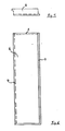
- Figure 1 shows a lightweight board 1 with double-sided fold 4 in a perspective view, in which the body is provided with air chambers 2.
- the arrangement of these air chambers 2 additionally reduces the weight of the lightweight building board 1.
- the board 1 becomes even more breathable without losing the sound and heat insulation properties.
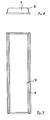
- FIG. 2 shows a lightweight board 3, in which the fold 4 runs around three edges and there is a groove 5 in the end face.
- Figure 3 shows the lightweight board 3 shown in Figure 2 in section.
- Figure 4 shows the side view of the lightweight board shown in Figure 2, in which the groove 5 can be clearly seen.
- Figure 5 shows a lightweight board 6 with mutually arranged fold 4, with a groove 5 is in turn arranged on one end face.
- Figure 6 shows the lightweight board shown in Figure 5 in section.
- Figure 7 shows a lightweight board 7, in which the fold inner edge has a bevel 8.
- the design is used to create truss walls or wooden beam ceilings.
- Figure 8 shows the lightweight board 7 shown in Figure 7 in section, in which the bevel 8 can be seen.
- FIG. 9 shows the components mentioned in FIGS. 1 to 8 in an assembly example.
- the components 3, 6 and 7 can be mounted not only next to one another but also opposite one another.
- a gap 15 is created between the components, which in turn can be filled with heat or sound insulation material.
- the wooden strips 16 used can take on constructive or optically aesthetic tasks.
- FIGS. 10-14 show further exemplary embodiments of the invention.
- So z. B. the rectangular or square tube profile 9 shown in FIG. 10 can be set up vertically as a support or used as wall formwork, assembly and / or ventilation shaft.
- the U-profile 10 shown in FIG. 11 is preferably suitable as formwork for concrete lintels and beams, and as cladding for installations, but also as an installation shaft.
- FIG. 12 shows an exemplary embodiment of the invention, in which the component takes the form of a hollow trapezoid 11. This profile is used for the construction of hollow ceilings.
- Figure 13 shows an angle profile 12 and is suitable for cladding installations, as shuttering of concrete ceilings and as cladding of components such as. B. flat roof edges.
- FIG. 14 shows an h-profile 13 suitable for roller shutter boxes with the ceiling formwork.
- the present invention represents an ideal kit with economic properties that make additional heat and sound insulation, possibly optical additions unnecessary.
- the invention further relates to a lightweight board consisting of pretreated straw and binder.
- the panel according to the invention can be designed as a sandwich panel, as panels and as an insulation panel.
- building materials including building boards
- these building materials should be made from so-called biological raw materials if possible in order to have environmentally friendly properties; they should also have sound-insulating and heat-insulating properties.
- these building materials, including building boards should be as flame-retardant as possible, water-repellent, waterproof and, if possible, non-flammable.
- the building materials should be as easy to process as possible, preferably in a dry process using simple hand tools.
- the building materials should also be finished as far as possible or the surface should allow or have a further coating using plywood, veneer, foil, cardboard or paints.
- the invention is therefore based on the object of creating a building material, namely a lightweight building board, which combines the above-mentioned requirements and properties.
- a lightweight building board which consists of pretreated straw and binder.
- This new lightweight board can be used to create components, sandwich panels and panels as well as insulation boards; the lightweight board according to the invention is particularly immune to moisture absorption. Its surface is coated or at least suitable for a final treatment such as covering wallpaper or painting.
- the lightweight board according to the invention is hard at the same time and can be processed with simple hand tools such as a saw and drill.
- the lightweight board according to the invention Due to its straw content, the lightweight board according to the invention has excellent heat and sound insulation and excellent tensile strength.
- the lightweight building board according to the invention represents a so-called biological building material and has excellent breathability.
- the lightweight board according to the invention Due to the relatively large occurrence of the raw material straw, which is a waste product, so to speak, the lightweight board according to the invention also has a major economic advantage over the previously known building materials.
- the lightweight board according to the invention is extremely environmentally friendly due to its biological properties.
- the straw is pretreated using means known per se which bring about the desired properties such as flame resistance, water repellency and the like. These agents are known in the art for cellulosic elements.
- connection of the pretreated straws or straw elements to the three-dimensional shape of the lightweight board is carried out using known adhesives or binders suitable for this purpose, optionally using heat and pressure according to known methods.
- the final coating of the lightweight board according to the invention is carried out using coating agents known per se for components made of wood or plastic.
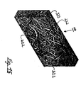
- FIG. 15 The subject of the present invention is shown in the accompanying FIG. 15.
- the subject of the invention namely the lightweight board in the form of a flat cuboid, is represented by reference number 111.
- the reference number 222 denotes the straw elements which are held together by the solidified binder 333 arranged in the spaces between the straw elements.
Landscapes
- Engineering & Computer Science (AREA)
- Architecture (AREA)
- Civil Engineering (AREA)
- Structural Engineering (AREA)
- Life Sciences & Earth Sciences (AREA)
- Wood Science & Technology (AREA)
- Building Environments (AREA)
- Finishing Walls (AREA)
- Panels For Use In Building Construction (AREA)
- Adhesives Or Adhesive Processes (AREA)
- Roof Covering Using Slabs Or Stiff Sheets (AREA)
Abstract
Description
- Die Erfindung betrifft einen Bausatz aus Leichtbauteilen zur Errichtung von Wänden, Stützen, Decken und sonstigen Bauteilen.sowie Leichtbauplatte. Heute verwendete Baustoffe sollen hinsichtlich der Verarbeitung wirtschaftliche Eigenschaften aufweisen. So ist es von Vorteil, wenn diese Baustoffe schall- und wärmedämmende Eigenschaften aufweisen , hierbei aber auch nicht brennbar sind und umweltfreundliches Grundmaterial verwendet wird.
Bezüglich der Wirtschaftlichkeit dürfen die auf der Baustelle auftretenden Probleme,wie leichte Verarbeitung, Beweglichkeit usw. nicht unbeachtet bleiben. - Nicht zuletzt sollten die verwendeten Bauteile den erforderlichen statischen Verhältnissen gerecht werden. Die heute verwendeten Bauteile entsprechen nicht oder nur teilweise diesen Anforderungen.
- Der Erfindung liegt daher die Aufgabe zugrunde, einen Bausatz bereitzustellen, der aus umweltfreundlichen nicht entflammbarem Baustoff geschaffen ist, wärmedämmend und den statischen Verhältnissen in seiner Form angepaßt werden kann.
- Diese Aufgabe wird erfindungsgemäß dadurch gelöst, daß der Bausatz aus Leichtbauteilen aus vorbehandeltem Stroh und Bindemittel geschaffenen Bauteilen besteht,
daß das Bauteil die Form einer Platte aufweist, deren Korpus mit Luftkammern versehen ist,
daß das Bauteil die Form einer Platte mit einer auf drei Kanten umlaufenden Falz und auf einer Kante befindlichen Nut aufweist,
daß das Bauteil die Form einer Platte, einen gegenseitig angeordneten Falz und an einer Kante eine Nut aufweist. - Weitere besonders bevorzugte Ausführungsformen sind dadurch gekennzeichnet,
daß das Bauteil die Form einer Platte aufweist, deren Falzinnenkante eine Abschrägung aufweist,
daß das Bauteil die Form eines Rechteckrohres aufweist,
daß das Bauteil eine U-Form aufweist,
daß das Bauteil als hohlförmiges Trapez mit beidseitigem Falz ausgebildet ist,
daß das Bauteil als Winkel ausgebildet ist,
daß das Bauteil h-förmig ausgebildet ist. - Eine weitere besondere Ausführungsform ist dadurch gekennzeichnet, daß das Bauteil mindestens an einer Frontfläche mit optischem oder witterungsbeständigem Material beschichtet sein kann.
- Anhand der beigefügten Zeichnungen, die besonders bevorzugte Ausführungsformen der Erfindung zeigen, wird diese nun näher erläutert.
Dabei zeigen: - Figur 1 eine Leichtbauplatte mit beidseitigem Falz und Luftkammern;
- Figur 2 eine Leichtbauplatte mit einem auf drei Kanten umlaufenden Falz und auf einer Kante befindlichen Nut;
- Figur 3 die Leichtbauplatte aus Figur 2 im Schnitt;
- Figur 4 eine Seitenansicht von Figur 2;
- Figur 5 die Leichtbauplatte mit gegenseitig angeordneten Falz und an einer Kante angeordneten Nut;
- Figur 6 die Leichtbauplatte aus Figur 5 im Schnitt;
- Figur 7 die Leichtbaupaltte mit abgeschrägter Falzinnenkante;
- Figur 8 die Leichtbauplatte aus Figur 7 im Schnitt;
- Figur 9 ein Ausführungsbeispiel eines montierten Bausatzes mit verschiedenen Bauteilen;
- Figur 10 bis Figur 14 weitere Profilausführungsbeispiele.
- Figur 1 zeigt eine Leichtbauplatte 1 mit beidseitigem Falz 4 in perspektivischer Darstellung,bei der der Korpus mit Luftkammern 2 versehen ist. Durch die Anordnung dieser Luftkammern 2 verringert sich zusätzlich das Eigengewicht der Leichtbauplatte 1. Darüberhinaus wird die Platte 1 noch atmungsfähiger, ohne die Schall- und Wärmedämmeigenschaften zu verlieren.
- Figur 2 zeigt eine Leichtbauplatte 3,bei der der Falz 4 drei Kanten umläuft und sich in der Stirnseite eine Nut 5 befindet.
- Figur 3 zeigt die in Figur 2 dargestellte Leichtbauplatte 3 im Schnitt.
- Figur 4 zeigt die Seitenansicht der in Figur 2 dargestellten Leichtbauplatte, bei der die Nut 5 deutlich zu erkennen ist.
- Figur 5 zeigt eine Leichtbauplatte 6 mit gegenseitig angeordnetem Falz 4, wobei wiederum an einer Stirnseite eine Nut 5 angeordnet ist.
- Figur 6 zeigt die in Figur 5 dargestellte Leichtbauplatte im Schnitt.
- Figur 7 zeigt eine Leichtbauplatte 7, bei der die Falzinnenkante eine Abschrägung 8 aufweist . Die Ausführungsart wird zur Erstellung von Fachwerkwänden oder Holzbalkendecken verwendet.
- Figur 8 zeigt die in Figur 7 dargestellte Leichtbauplatte 7 im Schnitt ,bei der die Abschrägung 8 erkennbar ist.
- Figur 9 zeigt die in Figur 1 bis 8 vorgenannten Bauteile in einem Montagebeispiel.
- Es ist eine besondere Eigenart der Erfindung, daß die Bauteile 3, 6 und 7 nicht nur nebeneinander sondern auch gegenüberliegend montiert werden können. Durch Verwendung eines entsprechenden Verbindungsstücks 14 entsteht zwischen den Bauteilen ein Spalt 15, der wiederum mit Wärme- oder Schalldämm-Material verfüllt werden kann.
- Die eingesetzten Holzleisten 16 können ebenso wie die Abschrägungen 8 konstruktive oder auch optisch ästhetische Aufgaben übernehmen.
- Die Figuren 10 - 14 zeigen weitere Ausführungsbeispiele der Erfindung.
So kann z. B. das in Figur 10 dargestellte Rechteck- bzw. Vierkantrohrprofil 9 als Stütze senkrecht aufgestellt werden oder als Wandschalung, Montage- und/oder Lüftungsschaft beliebig verwendet werden. - Das in Figur 11 gezeigte U-Profil 10 eignet sich vorzugsweise als Schalung für Betonstürze und Unterzüge, sowie als Verkleidung von Installationen aber auch als Installationsschacht.
- Figur 12 zeigt ein Ausführungsbeispiel der Erfindung, bei der das Bauelement die Form eines hohlen Trapez 11 einnimmt. Dieses Profil wird für die Errichtung von Hohlkörperdecken verwendet.
- Figur 13 zeigt ein Winkelprofil 12 und eignet sich zur Verkleidung von Installationen, als Abschalung von Betondecken und als Verkleidung von Bauteilen,wie z. B. Flachdachkanten.
- Figur 14 stellt ein für Rolladenkästen mit der Deckenabschalung geeignetes h-Profil 13 dar.
- All die vorgenannten Profilbeispiele weisen hervorragende Wärme- und Schalldämmeigenschaften auf und lassen sich je nach den statischen Erfordernissen in ihrer Formgebung verändern.
- Selbstverständlich besteht die Möglichkeit alle Bauteile an den entsprechenden Fronten mit Materialien zu beschichten, die den Witterungsverhältnissen und den optischen Vorstellung entsprechen.
- Die vorliegende Erfindung stellt einen idealen Bausatz mit wirtschaftlichen Eigenschaften dar, die eine zusätzliche Wärme- und Schalldämmung, gegebenenfalls optische Ergänzungen erübrigen.
- Die Erfindung betrifft ferner eine Leichtbauplatte, die aus vorbehandeltem Stroh und Bindemittel besteht.
- Die erfindungsgemäße Platte kann als Sandwich-Platte, als Panele und als Dämmplatte ausgebildet sein.
- Nach den heutigen Anforderungen sollen Baustoffe, also auch Bauplatten möglichst aus sogenannten biologischen Rohstoffen hergestellt sein, um umweltfreundliche Eigenschaften zu haben; sie sollen ferner möglichst schalldämmende und wärmedämmende Eigenschaften aufweisen. Ferner sollen diese Baustoffe, also auch Bauplatten möglichst schwer entflammbar, wasserabweisend, wasserfest und möglichst auch nicht brennbar sein.
- Die Baustoffe, also auch die Bauplatten, sollen möglichst leicht zu verarbeiten sein und zwar vorzugsweise im trockenen Verfahren unter Einsatz von einfachen Handwerkzeugen. Die Baustoffe sollen ferner möglichst endbeschichtet sein oder die Oberfläche soll eine weitere Beschichtung mittels Sperrholz, Furnier, Folie, Pappe oder Anstrichen zulassen bzw. aufweisen.
- Alle diese Anforderungen werden von den bisher bekannten Baustoffen meist nicht oder nur teilweise erfüllt.
- Der Erfindung liegt daher die Aufgabe zugrunde, einen Baustoff, nämlich eine Leichtbauplatte zu schaffen, die die oben genannten Anforderungen und Eigenschaften in sich vereint.
- Die Aufgabe wird dadurch gelöst, daß erfindungsgemäß eine Leichtbauplatte geschaffen wird, die aus vorbehandeltem Stroh und Bindemittel besteht.
- Diese neue Leichtbauplatte läßt sich zur Erstellung von Bauelementen, Sandwich-Platten und Panelen sowie von Dämmplatten verwenden; die erfindungsgemäße Leichtbauplatte ist insbesondere auch gegen Feuchtigkeitsaufnahme gefeit. Ihre Oberfläche ist endbeschichtet oder zumindest für eine Endbehandlung wie eine Auflage von Tapeten bzw. für einen Anstrich geeignet.
- Die erfindungsgemäße Leichtbauplatte ist gleichzeitig hart und läßt sich mit einfachen Handwerkzeugen wie Säge und Bohrer bearbeiten.
- Durch ihren Strohanteil besitzt die erfindungsgemäße Leichtbauplatte eine ausgezeichnete Wärme- und Schalldämmung sowie eine hervorragende Zugfëstigkeit.
- Die erfindungsgemäße Leichtbauplatte stellt durch ihren Strohanteil einen sogenannten biologischen Baustoff dar und besitzt eine ausgezeichnete Atmungsfähigkeit.
- Durch das relativ große Vorkommen des Rohstoffes Stroh, der sozusagen als Abfallprodukt anfällt, besitzt die erfindungsgemäße Leichtbauplatte gegenüber den bisher bekannten Baustoffen auch wirtschaftlich einen großen Vorteil.
- Ferner ist die erfindungsgemäße Leichtbauplatte infolge ihrer biologischen Eigenschaften extrem umweltfreundlich.
- Die Vorbehandlung des Strohs geschieht mit an sich bekannten Mitteln, die die gewünschten Eigenschaften wie schwere Entflammbarkeit, Wasserabweisung und dergleichen bewirken. Diese Mittel sind dem Stand der Technik für zellulosehaltige Elemente bekannt.
- Die Verbindung der vorbehandelten Strohhalme bzw. Strohelemente zur Raumform der Leichtbauplatte geschieht unter Anwendung an sich bekannter, für diesen Zweck geeigneter Klebstoffe bzw. Bindemittel, gegebenenfalls unter Anwendung von Hitze und Druck nach an sich bekannten Verfahren.
- Die Endbeschichtung der erfindungsgemäßen Leichtbauplatte geschieht mit an sich für Bauelemente aus Holz oder Kunststoff bekannten Beschichtungsmitteln.
- Der Gegenstand vorliegender Erfindung ist in der beiliegenden Figur 15 dargestellt.
- Dabei ist mit dem Bezugszeichen 111 der Erfindungsgegenstand, nämlich die Leichtbauplatte in Gestalt eines flachen Quaders dargestellt.
- Mit dem Bezugszeichen 222 sind die Strohhalmelemente gekennzeichnet, die durch das in den Zwischenräumen zwischen den Strohelementen angeordnete verfestigte Bindemittel 333 zusammengehalten werden.
-
- 1 Platte
- 2 Luftkammern
- 3 Platte mit drei Falzen und einer Nut
- 4 Falz
- 5 Nut
- 6 Platte mit gegenseitig angeordnetem Falz und einer Nut
- 7 Platte mit Falzabschrägung
- 8 Abschrägung
- 9 Bauteil in Rechteckrohrform
- 10 Bauteil in U-Form
- 11 Bauteil in Hohltrapezform
- 12 Bauteil in Winkelform
- 13 Bauteil in h-Form
- 14 Verbindungsstück
- 15 Spalt zwischen Bauteilen
- 16 Holzleisten
- 111 Leichtbauplatte
- 222 Strohhalteelement
- 333 Bindemittel
Claims (20)
dadurch gekennzeichnet,
daß er aus vorbehandeltem Stroh und Bindemittel geschaffenen Bauteilen besteht.
dadurch gekennzeichnet,
daß das Bauteil die Form einer Platte (1) aufweist, deren Korpus mit Luftkammern (2) versehen ist.
dadurch gekennzeichnet,
daß das Bauteil die Form einer Platte (3) mit einer auf drei Kanten umlaufenden Falz (4) und auf einer Kante befindlichen Nut (5) aufweist.
dadurch gekennzeichnet,
daß das Bauteil die Form einer Platte (6), einen gegenseitig angeordneten Falz (4) und an einer Kante eine Nut (5) aufweist.
dadurch gekennzeichnet,
daß das Bauteil die Form einer Platte (7) aufweist, deren Falzinnenkante eine Abschrägung (8) aufweist.
dadurch gekennzeichnet,
daß das Bauteil die Form eines Rechteckrohres (9) aufweist.
dadurch gekennzeichnet,
daß das Bauteil eine U-Form (10) aufweist.
dadurch gekennzeichnet,
daß das Bauteil als hohlförmiges Trapez (11) mit beideseitigem Falz (4) ausgebildet ist.
dadurch gekennzeichnet,
daß das Bauteil als Winkel (12) ausgebildet ist.
dadurch gekennzeichnet,
daß das Bauteil h-förmig (13) ausgebildet ist.
dadurch gekennzeichnet,
daß das Bauteil mindestens an einer Frontfläche mit optischem oder witterungsbeständigem Material beschichtet ist.
dadurch gekennzeichnet,
daß sie aus vorbehandeltem Stroh (Strohhalmen) und verfestigtem Bindemittel besteht.
dadurch gekennzeichnet,
daß sie mit an sich bekannten Mitteln endbeschichtet ist.
dadurch gekennzeichnet,
daß sie mit Sperrholz beschichtet ist.
dadurch gekennzeichnet,
daß sie mit Furnier beschichtet ist.
dadurch gekennzeichnet,
daß sie mit Folie beschichtet ist.
dadurch gekennzeichnet,
daß sie mit Pappe beschichtet ist.
dadurch gekennzeichnet,
daß die Leichtbauplatte eine Anstrichbeschichtung aufweist.
dadurch gekennzeichnet,
daß die Strohelemente mit einem an sich bekannten flammhemmenden Mittel vorbehandelt bzw. überzogen bzw. imprägniert sind.
dadurch gekennzeichnet,
daß die Strohelemente mit einem an sich bekannten wasserabweisenden Mittel vorbehandelt bzw. überzogen bzw. imprägniert sind.
Priority Applications (1)
| Application Number | Priority Date | Filing Date | Title |
|---|---|---|---|
| AT87117384T ATE72000T1 (de) | 1986-12-03 | 1987-11-25 | Bausatz aus leichtbauteilen fuer waende, stuetzen, decken und sonstigen bauteilen sowie leichtbauplatte. |
Applications Claiming Priority (4)
| Application Number | Priority Date | Filing Date | Title |
|---|---|---|---|
| DE8632320U | 1986-12-03 | ||
| DE8632320U DE8632320U1 (de) | 1986-12-03 | 1986-12-03 | Leichtbauplatte |
| DE8706757U DE8706757U1 (de) | 1987-05-12 | 1987-05-12 | Bausatz aus Leichtbauteilen für Wände, Stützen, Decken und sonstigen Bauteilen |
| DE8706757U | 1987-05-12 |
Publications (3)
| Publication Number | Publication Date |
|---|---|
| EP0269990A2 true EP0269990A2 (de) | 1988-06-08 |
| EP0269990A3 EP0269990A3 (en) | 1989-05-10 |
| EP0269990B1 EP0269990B1 (de) | 1992-01-22 |
Family
ID=25951272
Family Applications (1)
| Application Number | Title | Priority Date | Filing Date |
|---|---|---|---|
| EP87117384A Expired - Lifetime EP0269990B1 (de) | 1986-12-03 | 1987-11-25 | Bausatz aus Leichtbauteilen für Wände, Stützen, Decken und sonstigen Bauteilen sowie Leichtbauplatte |
Country Status (6)
| Country | Link |
|---|---|
| EP (1) | EP0269990B1 (de) |
| AT (1) | ATE72000T1 (de) |
| CA (1) | CA1293354C (de) |
| DE (1) | DE3776293D1 (de) |
| ES (1) | ES2030416T3 (de) |
| GR (1) | GR3004438T3 (de) |
Cited By (2)
| Publication number | Priority date | Publication date | Assignee | Title |
|---|---|---|---|---|
| WO2001034498A1 (fr) | 1999-11-12 | 2001-05-17 | Denis Morillon | Materiau de calage compressible biodegradable et procede de fabrication |
| ITPS20080022A1 (it) * | 2008-09-02 | 2010-03-02 | Max Canti | Processo per ottenere in continuo materiale isolante termoacustico e barriera al fuoco per costruzioni navali od edilizia ad elevato sviluppo verticale. elementi con esso ottenuti. |
Families Citing this family (6)
| Publication number | Priority date | Publication date | Assignee | Title |
|---|---|---|---|---|
| US5177924A (en) * | 1986-12-03 | 1993-01-12 | Stefan Kakuk | Lightweight building component |
| DE9000238U1 (de) * | 1990-01-11 | 1990-04-19 | Kakuk, Stefan, 68794 Oberhausen-Rheinhausen | Bausatz aus Leichtbauteilen für Wände, Stützen, Decken und sonstigen Bauteilen |
| DE4126756A1 (de) * | 1991-08-13 | 1993-02-18 | Schaaf Technologie Gmbh | Verfahren zum herstellen neuer verpackungsstoffe oder isolierbaustoffe als ersatz von polystyrol-chips bzw. polystyrol-kuegelchen oder polyurethanschaumprodukte sowie expandiertes material |
| GB2277751A (en) * | 1993-04-21 | 1994-11-09 | Dale Mccrea | A structural element and a method for its production |
| DE4401983C2 (de) * | 1994-01-25 | 1996-02-15 | Peter Bruchmann | Dämmstoffmaterial aus Stroh, dessen Herstellung und Verwendung |
| DE29510380U1 (de) * | 1995-06-27 | 1996-10-31 | Kakuk, Stefan, 68794 Oberhausen-Rheinhausen | Leichtbauteile mit Faserarmierung |
Citations (3)
| Publication number | Priority date | Publication date | Assignee | Title |
|---|---|---|---|---|
| DE950409C (de) * | 1944-09-02 | 1956-10-11 | Josef L Halter | Verfahren zur Herstellung von Leichtbaukoerpern |
| FR2081257A1 (de) * | 1970-03-20 | 1971-12-03 | Giel Alexandre | |
| DE8536156U1 (de) * | 1985-12-21 | 1986-02-20 | Moll, Lothar, 6830 Schwetzingen | Strohdämmplatte |
-
1987
- 1987-11-25 EP EP87117384A patent/EP0269990B1/de not_active Expired - Lifetime
- 1987-11-25 ES ES198787117384T patent/ES2030416T3/es not_active Expired - Lifetime
- 1987-11-25 AT AT87117384T patent/ATE72000T1/de not_active IP Right Cessation
- 1987-11-25 DE DE8787117384T patent/DE3776293D1/de not_active Expired - Lifetime
- 1987-12-03 CA CA000553457A patent/CA1293354C/en not_active Expired - Lifetime
-
1992
- 1992-04-22 GR GR920400810T patent/GR3004438T3/el unknown
Patent Citations (3)
| Publication number | Priority date | Publication date | Assignee | Title |
|---|---|---|---|---|
| DE950409C (de) * | 1944-09-02 | 1956-10-11 | Josef L Halter | Verfahren zur Herstellung von Leichtbaukoerpern |
| FR2081257A1 (de) * | 1970-03-20 | 1971-12-03 | Giel Alexandre | |
| DE8536156U1 (de) * | 1985-12-21 | 1986-02-20 | Moll, Lothar, 6830 Schwetzingen | Strohdämmplatte |
Cited By (3)
| Publication number | Priority date | Publication date | Assignee | Title |
|---|---|---|---|---|
| WO2001034498A1 (fr) | 1999-11-12 | 2001-05-17 | Denis Morillon | Materiau de calage compressible biodegradable et procede de fabrication |
| FR2801041A1 (fr) | 1999-11-12 | 2001-05-18 | Denis Morillon | Materiau de calage compressible biodegradable et procede de fabrication |
| ITPS20080022A1 (it) * | 2008-09-02 | 2010-03-02 | Max Canti | Processo per ottenere in continuo materiale isolante termoacustico e barriera al fuoco per costruzioni navali od edilizia ad elevato sviluppo verticale. elementi con esso ottenuti. |
Also Published As
| Publication number | Publication date |
|---|---|
| EP0269990A3 (en) | 1989-05-10 |
| EP0269990B1 (de) | 1992-01-22 |
| ATE72000T1 (de) | 1992-02-15 |
| GR3004438T3 (de) | 1993-03-31 |
| DE3776293D1 (de) | 1992-03-05 |
| ES2030416T3 (es) | 1992-11-01 |
| CA1293354C (en) | 1991-12-24 |
Similar Documents
| Publication | Publication Date | Title |
|---|---|---|
| DE3177307T2 (de) | Rahmen zur Einfassung eines Teiles einer Wand. | |
| DE19523131A1 (de) | Mehrschichtige Wand in Holzrahmen-Bauweise, hieraus aufgebautes Holzrahmenbauteil, sowie hiermit errichtetes Haus, insbesondere Niedrigenergiehaus | |
| DE3223098A1 (de) | Wandelement fuer fertighaeuser | |
| EP0269990A2 (de) | Bausatz aus Leichtbauteilen für Wände, Stützen, Decken und sonstigen Bauteilen sowie Leichtbauplatte | |
| DE9000238U1 (de) | Bausatz aus Leichtbauteilen für Wände, Stützen, Decken und sonstigen Bauteilen | |
| EP3792424A1 (de) | Wand- und dachbekleidungselement, wand- und dachbekleidungssystem, insbesondere hinterlüftetes oder hinterlüftbares wand- und dachbekleidungssystem, sowie wand, insbesondere holzrahmenbauwand, und dach | |
| DE102007045122A1 (de) | Trockenbausystem für Innen- und Aussenanwendungen | |
| DE2705842A1 (de) | Baumaterialien fuer das bauwesen | |
| EP2820197B1 (de) | Dämmelement | |
| AT403936B (de) | Wandelement | |
| DE202018105079U1 (de) | Neue wärmedämmende und rissbeständige Wandbauplatte | |
| DE8632320U1 (de) | Leichtbauplatte | |
| DE10125349B4 (de) | Holzwandtafel | |
| DE826633C (de) | Plattenfoermiges Bauelement, vornehmlich zur Herstellung von Aussenwaenden, Zwischenwaenden u. dgl. | |
| DE102006010281B4 (de) | Verfahren zur Aufnahme von Rollläden oder Jalousien | |
| DE29611948U1 (de) | Rolladenkasten | |
| DE9419795U1 (de) | Wandkonstruktion für und Bauwerk in Ständerbauweise | |
| DE20000475U1 (de) | Mehrschichtplatte für den Hochbau | |
| DE2427072A1 (de) | Verfahren zur verstaerkung der kanten von faserplatten und nach diesem verfahren verstaerkte faserplatten | |
| EP3075936A1 (de) | Dämmplattenelement zur dämmung einer fenster- oder türlaibung und verfahren zur bildung einer fenster-oder türlaibung | |
| DE8122237U1 (de) | Abstellwinkel fuer die stirnseiten von betondecken | |
| DE2600372A1 (de) | Fassadenplatte | |
| DE804715C (de) | Bau- und Isolierplatte | |
| DE8706757U1 (de) | Bausatz aus Leichtbauteilen für Wände, Stützen, Decken und sonstigen Bauteilen | |
| EP3067483B1 (de) | Wandaufbau für ein Gebäudesystem, insbesondere Wohngebäude |
Legal Events
| Date | Code | Title | Description |
|---|---|---|---|
| PUAI | Public reference made under article 153(3) epc to a published international application that has entered the european phase |
Free format text: ORIGINAL CODE: 0009012 |
|
| AK | Designated contracting states |
Kind code of ref document: A2 Designated state(s): AT BE CH DE ES FR GB GR IT LI LU NL SE |
|
| PUAL | Search report despatched |
Free format text: ORIGINAL CODE: 0009013 |
|
| AK | Designated contracting states |
Kind code of ref document: A3 Designated state(s): AT BE CH DE ES FR GB GR IT LI LU NL SE |
|
| 17P | Request for examination filed |
Effective date: 19890902 |
|
| 17Q | First examination report despatched |
Effective date: 19900316 |
|
| GRAA | (expected) grant |
Free format text: ORIGINAL CODE: 0009210 |
|
| AK | Designated contracting states |
Kind code of ref document: B1 Designated state(s): AT BE CH DE ES FR GB GR IT LI LU NL SE |
|
| REF | Corresponds to: |
Ref document number: 72000 Country of ref document: AT Date of ref document: 19920215 Kind code of ref document: T |
|
| REF | Corresponds to: |
Ref document number: 3776293 Country of ref document: DE Date of ref document: 19920305 |
|
| ITF | It: translation for a ep patent filed | ||
| GBT | Gb: translation of ep patent filed (gb section 77(6)(a)/1977) | ||
| ET | Fr: translation filed | ||
| REG | Reference to a national code |
Ref country code: ES Ref legal event code: FG2A Ref document number: 2030416 Country of ref document: ES Kind code of ref document: T3 |
|
| PLBE | No opposition filed within time limit |
Free format text: ORIGINAL CODE: 0009261 |
|
| STAA | Information on the status of an ep patent application or granted ep patent |
Free format text: STATUS: NO OPPOSITION FILED WITHIN TIME LIMIT |
|
| REG | Reference to a national code |
Ref country code: GR Ref legal event code: FG4A Free format text: 3004438 |
|
| 26N | No opposition filed | ||
| EPTA | Lu: last paid annual fee | ||
| EAL | Se: european patent in force in sweden |
Ref document number: 87117384.5 |
|
| PGFP | Annual fee paid to national office [announced via postgrant information from national office to epo] |
Ref country code: GB Payment date: 19971125 Year of fee payment: 11 |
|
| PGFP | Annual fee paid to national office [announced via postgrant information from national office to epo] |
Ref country code: AT Payment date: 19971126 Year of fee payment: 11 |
|
| PGFP | Annual fee paid to national office [announced via postgrant information from national office to epo] |
Ref country code: SE Payment date: 19971127 Year of fee payment: 11 Ref country code: GR Payment date: 19971127 Year of fee payment: 11 |
|
| PGFP | Annual fee paid to national office [announced via postgrant information from national office to epo] |
Ref country code: FR Payment date: 19971128 Year of fee payment: 11 |
|
| PGFP | Annual fee paid to national office [announced via postgrant information from national office to epo] |
Ref country code: NL Payment date: 19971130 Year of fee payment: 11 |
|
| PGFP | Annual fee paid to national office [announced via postgrant information from national office to epo] |
Ref country code: CH Payment date: 19971202 Year of fee payment: 11 |
|
| PGFP | Annual fee paid to national office [announced via postgrant information from national office to epo] |
Ref country code: DE Payment date: 19971203 Year of fee payment: 11 |
|
| PGFP | Annual fee paid to national office [announced via postgrant information from national office to epo] |
Ref country code: LU Payment date: 19971209 Year of fee payment: 11 |
|
| PGFP | Annual fee paid to national office [announced via postgrant information from national office to epo] |
Ref country code: BE Payment date: 19980108 Year of fee payment: 11 |
|
| PG25 | Lapsed in a contracting state [announced via postgrant information from national office to epo] |
Ref country code: LU Free format text: LAPSE BECAUSE OF NON-PAYMENT OF DUE FEES Effective date: 19981125 Ref country code: GB Free format text: LAPSE BECAUSE OF NON-PAYMENT OF DUE FEES Effective date: 19981125 Ref country code: AT Free format text: LAPSE BECAUSE OF NON-PAYMENT OF DUE FEES Effective date: 19981125 |
|
| PG25 | Lapsed in a contracting state [announced via postgrant information from national office to epo] |
Ref country code: SE Free format text: LAPSE BECAUSE OF NON-PAYMENT OF DUE FEES Effective date: 19981126 |
|
| PG25 | Lapsed in a contracting state [announced via postgrant information from national office to epo] |
Ref country code: LI Free format text: LAPSE BECAUSE OF NON-PAYMENT OF DUE FEES Effective date: 19981130 Ref country code: GR Free format text: LAPSE BECAUSE OF NON-PAYMENT OF DUE FEES Effective date: 19981130 Ref country code: CH Free format text: LAPSE BECAUSE OF NON-PAYMENT OF DUE FEES Effective date: 19981130 Ref country code: BE Free format text: LAPSE BECAUSE OF NON-PAYMENT OF DUE FEES Effective date: 19981130 |
|
| PGFP | Annual fee paid to national office [announced via postgrant information from national office to epo] |
Ref country code: ES Payment date: 19990323 Year of fee payment: 12 |
|
| BERE | Be: lapsed |
Owner name: KAKUK STEFAN Effective date: 19981130 |
|
| PG25 | Lapsed in a contracting state [announced via postgrant information from national office to epo] |
Ref country code: NL Free format text: LAPSE BECAUSE OF NON-PAYMENT OF DUE FEES Effective date: 19990601 |
|
| GBPC | Gb: european patent ceased through non-payment of renewal fee |
Effective date: 19981125 |
|
| REG | Reference to a national code |
Ref country code: CH Ref legal event code: PL |
|
| PG25 | Lapsed in a contracting state [announced via postgrant information from national office to epo] |
Ref country code: FR Free format text: LAPSE BECAUSE OF NON-PAYMENT OF DUE FEES Effective date: 19990730 |
|
| EUG | Se: european patent has lapsed |
Ref document number: 87117384.5 |
|
| NLV4 | Nl: lapsed or anulled due to non-payment of the annual fee |
Effective date: 19990601 |
|
| REG | Reference to a national code |
Ref country code: FR Ref legal event code: ST |
|
| PG25 | Lapsed in a contracting state [announced via postgrant information from national office to epo] |
Ref country code: DE Free format text: LAPSE BECAUSE OF NON-PAYMENT OF DUE FEES Effective date: 19990901 |
|
| PG25 | Lapsed in a contracting state [announced via postgrant information from national office to epo] |
Ref country code: ES Free format text: LAPSE BECAUSE OF NON-PAYMENT OF DUE FEES Effective date: 19991126 |
|
| REG | Reference to a national code |
Ref country code: ES Ref legal event code: FD2A Effective date: 20001214 |
|
| PG25 | Lapsed in a contracting state [announced via postgrant information from national office to epo] |
Ref country code: IT Free format text: LAPSE BECAUSE OF NON-PAYMENT OF DUE FEES;WARNING: LAPSES OF ITALIAN PATENTS WITH EFFECTIVE DATE BEFORE 2007 MAY HAVE OCCURRED AT ANY TIME BEFORE 2007. THE CORRECT EFFECTIVE DATE MAY BE DIFFERENT FROM THE ONE RECORDED. Effective date: 20051125 |