EP0266684A2 - Méthode et sécheur comprenant un dispositif de régénération d'une cartouche de séchage chargée d'humidité - Google Patents
Méthode et sécheur comprenant un dispositif de régénération d'une cartouche de séchage chargée d'humidité Download PDFInfo
- Publication number
- EP0266684A2 EP0266684A2 EP87115942A EP87115942A EP0266684A2 EP 0266684 A2 EP0266684 A2 EP 0266684A2 EP 87115942 A EP87115942 A EP 87115942A EP 87115942 A EP87115942 A EP 87115942A EP 0266684 A2 EP0266684 A2 EP 0266684A2
- Authority
- EP
- European Patent Office
- Prior art keywords
- drying
- cartridge
- regeneration
- air
- circuit
- Prior art date
- Legal status (The legal status is an assumption and is not a legal conclusion. Google has not performed a legal analysis and makes no representation as to the accuracy of the status listed.)
- Granted
Links
Images


Classifications
-
- F—MECHANICAL ENGINEERING; LIGHTING; HEATING; WEAPONS; BLASTING
- F26—DRYING
- F26B—DRYING SOLID MATERIALS OR OBJECTS BY REMOVING LIQUID THEREFROM
- F26B21/00—Arrangements for supplying or controlling air or other gases for drying solid materials or objects
- F26B21/30—Controlling, e.g. regulating, parameters of gas supply
- F26B21/33—Humidity
- F26B21/331—Humidity by using sorbent or hygroscopic materials, e.g. chemical substances or molecular sieves
-
- B—PERFORMING OPERATIONS; TRANSPORTING
- B01—PHYSICAL OR CHEMICAL PROCESSES OR APPARATUS IN GENERAL
- B01D—SEPARATION
- B01D53/00—Separation of gases or vapours; Recovering vapours of volatile solvents from gases; Chemical or biological purification of waste gases, e.g. engine exhaust gases, smoke, fumes, flue gases, aerosols
- B01D53/26—Drying gases or vapours
- B01D53/261—Drying gases or vapours by adsorption
-
- B—PERFORMING OPERATIONS; TRANSPORTING
- B29—WORKING OF PLASTICS; WORKING OF SUBSTANCES IN A PLASTIC STATE IN GENERAL
- B29B—PREPARATION OR PRETREATMENT OF THE MATERIAL TO BE SHAPED; MAKING GRANULES OR PREFORMS; RECOVERY OF PLASTICS OR OTHER CONSTITUENTS OF WASTE MATERIAL CONTAINING PLASTICS
- B29B13/00—Conditioning or physical treatment of the material to be shaped
- B29B13/06—Conditioning or physical treatment of the material to be shaped by drying
- B29B13/065—Conditioning or physical treatment of the material to be shaped by drying of powder or pellets
-
- F—MECHANICAL ENGINEERING; LIGHTING; HEATING; WEAPONS; BLASTING
- F26—DRYING
- F26B—DRYING SOLID MATERIALS OR OBJECTS BY REMOVING LIQUID THEREFROM
- F26B21/00—Arrangements for supplying or controlling air or other gases for drying solid materials or objects
- F26B21/20—Circulating air or gases in closed cycles, e.g. wholly within the drying enclosure
- F26B21/25—Circulating air or gases in closed cycles, e.g. wholly within the drying enclosure partly outside the drying enclosure
-
- B—PERFORMING OPERATIONS; TRANSPORTING
- B29—WORKING OF PLASTICS; WORKING OF SUBSTANCES IN A PLASTIC STATE IN GENERAL
- B29B—PREPARATION OR PRETREATMENT OF THE MATERIAL TO BE SHAPED; MAKING GRANULES OR PREFORMS; RECOVERY OF PLASTICS OR OTHER CONSTITUENTS OF WASTE MATERIAL CONTAINING PLASTICS
- B29B9/00—Making granules
- B29B9/16—Auxiliary treatment of granules
Definitions
- the invention relates to a method for regenerating a drying cartridge loaded with moisture according to the preamble of claim 1 and a device for carrying out such a method according to the preamble of claim 7.
- Drying cartridges are used to prepare drying air for drying plastics, which can be in the form of granules and powder.
- the drying air is first passed through the material to be dried, the drying air absorbing moisture from the material.
- This air which is laden with moisture, is then passed through the drying cartridge, which absorbs the moisture from the drying air.
- the drying air then returns to the material to be dried. This drying process is continued until the drying cartridge can absorb almost no moisture from the drying air.
- Continuous processes use several, usually two to four drying cartridges, one of which is always regenerated. This means that there are always enough drying cartridges available. In the case of discontinuously operating systems, only one drying cartridge is used, which can be used until the dew point has a correspondingly high temperature and can only absorb a little moisture from the drying air.
- this drying cartridge must be regenerated.
- atmospheric air is heated and passed through the cartridge to be regenerated, the heated air being the Absorbs moisture from the cartridge to be regenerated.
- the regeneration air is heated in order to absorb the moisture as quickly as possible.
- the regeneration air laden with moisture is blown out.
- atmospheric air is continuously taken in from the outside, heated before entering the cartridge to be regenerated and blown out again after it has passed through the cartridge.
- the blown air contains a high proportion of energy that is blown out unused. To heat the atmospheric air, considerable energy must also be expended in order to heat the always flowing cool atmospheric air to the desired drying temperature.
- the cartridge to be regenerated must be cooled after the regeneration before it can be used again to dry the material.
- the heating device is switched off in the known method and only the cool atmospheric air is guided through the dried cartridge. This atmospheric air partially humidifies the cartridge, so that the efficiency of the device operating according to this method is impaired.
- the invention has for its object to design the generic method and the generic device so that an optimal lowest possible dew point is achieved after the regeneration of the cartridge, the energy required for the regeneration should be as small as possible.
- the regeneration air is passed through the cartridge to be regenerated in a closed regeneration circuit.
- almost no energy loss in this closed system - energy losses due to insulation are negligible - the moisture in the cartridge to be regenerated can be expelled without the need for a costly heat exchanger for the exhaust air from a closed circuit or the like.
- no new atmospheric air is supplied from the outside, so that even little energy is required to heat the regeneration air.
- the air When passing through the cartridge to be regenerated, the air only loses as much energy as it needs to heat the cartridge and to evaporate the moisture in the cartridge. It is therefore essentially only necessary to supply the evaporation energy of the regeneration air flowing in the circuit again.
- the regenerated cartridge delivers optimal results when the material is subsequently dried.
- the cartridge which has been dried and heated during regeneration, is then cooled, the cooling air likewise being passed through the cartridge in the closed regeneration circuit. No atmospheric moist air is thus supplied from the outside during cooling, so that the cartridge has the lowest possible dew point after cooling.
- the recooling energy released in this cooling process can be used economically via a heat exchanger, for example for heating the drying air used to dry the material. However, it is also possible to economically dissipate the released energy. This is necessary, for example, if the cooling air, after passing through the regenerated cartridge to be cooled, is still so high that it cannot be used to dry the material.
- the heat to cool the cooling air within the regeneration circuit to lead exchanger, which absorbs the heat from the cooling air and releases it to the environment.
- the energy of the hot, regenerated cartridge can always be removed via the heat exchanger in the drying circuit, regulation being provided so that the temperature of the drying circuit does not become too high.
- An optimal lowest possible dew point after the regeneration of the cartridge to be regenerated with the lowest total energy expenditure results because both the drying and the cooling during regeneration are each carried out in a closed regeneration circuit.
- the regeneration line in which the cartridge to be regenerated is located, is part of the closed regeneration circuit.
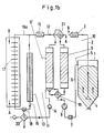
- drying air material located in a drying container 1, preferably plastic granules or powder, is dried by means of dry air, so-called drying air.
- the mouth 4 of the feed line 2 lies in the region of the bottom of the drying container, so that the dry air emerging from it flows upward in the drying container in the direction of the arrows shown.
- In the upper area of the drying container 1 there is an outlet 5 to which a return line 6 is connected.
- a filter 7 In it there is a filter 7 in order to collect dust and the like contained in the drying air flowing from the drying container.
- the return line 6 there is also a blower 8 which lies between the filter 7 and a drying cartridge 9 into which the return line 6 opens.
- the feed line 2 is also connected to the drying cartridge 9.
- the heating device 3 is located in the flow direction behind the drying cartridge, which is preferably a molecular sieve cartridge.
- the powder or granules to be dried are found in the drying container 1.
- the drying air flows via the feed line 2 into the drying container 1 and flows through the granules or the powder.
- the drying air absorbs moisture from the granules or powder and flows through the return line 6 and the filter 7 into the drying cartridge 9, where the moisture absorbed by the drying air is retained, so that dry air again reaches the drying container 1 via the supply line 2 .
- the drying air in the supply line 2 is heated to the required temperature with the heating device 3.
- the drying air is thus conducted in a drying circuit 10, the powder or the granules being dried to the desired extent.
- only one drying cartridge 9 is shown in the drying circuit 10. Of course, it is possible to use several drying cartridges 9 in the drying circuit 10.
- the drying air is circulated until the material to be dried in the container 1 is sufficiently dehumidified.
- the drying cartridge 9 is exhausted and can only absorb a little moisture from the drying air, it is regenerated.
- the device is provided with a regeneration circuit 11 in which the cartridge 9 ⁇ to be regenerated lies.
- a line 12 is connected to it, which, as shown only schematically in FIG. 1a with the aid of a line branch 16, is surrounded by insulation 13. All lines are preferably insulated from the atmosphere separately.
- a blower 14 In the flow direction of the regeneration air behind the cartridge 9 ⁇ to be regenerated there is a blower 14 and a heating device 15 in the line 12. It lies between the blowers 14 and the cartridge 9 ⁇ .
- the line 12 also has a line branch 16a in which there is a heat exchanger 17, which is preferably also insulated from the outside.
- the line branch 16a can be opened or closed via a valve 18.
- the line branch 16a is closed, so that the regeneration air flows in the regeneration circuit 11 in the direction of the arrows shown.
- dry air is passed through the cartridge 9 ⁇ , this air absorbing the moisture from the cartridge 9 ⁇ and thus drying it.
- the water in the cartridge 9 ⁇ must be transferred in vapor form. Therefore, the regeneration air with the heater 15 is heated so strongly before entering the cartridge 9 ⁇ (to about 180 ° C to 250 ° C) that the liquid in the cartridge 9 ⁇ is converted into vapor form and can thus be absorbed by it.
- the air emerging from the cartridge 9 ⁇ has cooled due to the transfer of the liquid into the vapor form, so that the heating device 15 heats the air again by this amount of cooling before entering the cartridge 9 Patr.
- This temperature difference corresponds essentially only to the evaporation energy which is necessary to convert the liquid in the cartridge 9 ⁇ into the vapor form. Since no atmospheric air gets into the regeneration circuit 11 during the drying process described, the cartridge 9 'can be optimally dehumidified in the regeneration circuit 11.
- the insulation 13 ensures that the heat losses when flowing through the line 12 are low, so that the heating device 15 only needs to heat the regeneration air a little.
- the closed regeneration circuit 11 allows the water in the cartridge 9 ⁇ to be evaporated practically without loss of energy.
- a valve 19 is installed, which has such a position in Fig. 1a that the drying air in the line 6 of the drying cartridge 9 and the regeneration air after leaving the cartridge to be regenerated 9 ⁇ of the heating device 15 is fed via the blower 14.
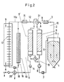
- the line 12 is opened briefly so that the regeneration air, which is now laden with moisture, can escape from the regeneration circuit 11.
- an outlet valve 20 is provided in the line 12 after the blower 14 and is opened in this case (FIG. 2).
- atmospheric new air flows at "X" into line 12, which can then be used to dry again after the outlet valve has been closed.
- the same or a different drying cartridge 9 ⁇ can now be dried in the manner described.
- the atmospheric air is slightly laden with moisture, the proportion of moisture within the regeneration circuit 11 is small, because no new atmospheric air is added during the regeneration process, but is instead conducted in the closed circuit.
- the line branch 16a remains closed during the blowing out of the used regeneration air and the drawing in of new atmospheric air. (Fig.2)
- the heating device 15 in the regeneration circuit 11 is switched off or, by switching the valve 18, is placed in the line part 16, through which cooling air does not flow (FIG. 3).
- the line branch 16a is opened via the valves 20, 18, so that the regeneration air in the direction of the arrows in Fig. 3 is circulated through the heat exchanger 17. Since the regeneration air is no longer heated, it can absorb heat when flowing through the dried cartridge 9 ⁇ and thereby cool it.
- the heated air emerging from the cartridge 9 ⁇ flows through the heat exchanger 17 and gives off its heat to it.
- the cartridge 9 ⁇ is cooled to the required temperature after drying (Fig.1a and 2).
- This optimal recooling temperature is the temperature that the drying cartridge has in the drying circuit. It should therefore be cooled back to the extent that when the recooling process ends, the two cartridges 9.9 ⁇ (in the regeneration circuit and in the drying circuit) have the same temperature. It is important to use the heat exchanger 17 in any case, since this is the most economical way to bring the two cartridges 9.9 ⁇ to the same temperature.
- the energy present in the hot (regenerated) cartridge 9 ⁇ can thus be fully used and the objective of the optimal recooling temperature is inevitably achieved without further effort.
- control valve 18 must be used instead of a changeover valve in the regeneration circuit 11 for the changeover from the heating phase to the recooling phase.
- a switching flap can also be provided instead of the control valve 18. It is closed after a first switchover to the heat exchanger 17 whenever the temperature in the drying circuit 10 exceeds the desired setpoint value and is switched over as soon as this temperature falls below again. Since the air is recirculated during recooling, ie no atmospheric, moisture-laden air is added, the cartridge 9 ⁇ is not already loaded with moisture during this cooling process. This procedure achieves an extremely low dew point, which is of the order of about -50 ° C to -70 ° C.
- the regeneration described thus becomes an optimal we efficiency of the device reached. If the cartridge 9 ⁇ has been cooled to the required temperature, it can be switched into the drying circuit 10 (Fig. 1b), so that it in turn the drying air conveyed in this circuit after passing through the material to be dried in the drying container 1 in the manner described can dehumidify.
- the described cooling of the regenerated cartridge 9 ⁇ is necessary if it is hotter than the inlet temperature of the air flowing in the drying circuit 10 when it enters the drying cartridge 9.
- the heat exchanger 17 is a known air-air exchanger.
- the waste heat emitted by the heat exchanger 17 during cooling can be used to heat the air in the drying circuit 10 or for other purposes. With the waste heat, the air in the drying circuit 10 can be heated when it has a certain minimum temperature, which, for. B. is about 70 ° C. In this case, the air in the drying circuit 10 can also be passed through the heat exchanger 17, whereby it absorbs the heat given off by it. As a result, the energy consumption of the device can be kept low.
- valve 19 and a valve 21 are used in a known manner, which are installed in the lines 6 and 12.
- the valve 21 is located in the flow direction of the drying air behind the cartridge 9 and in the flow direction of the regeneration air in front of the cartridge 9 ⁇ (Fig.1a).
- flaps, rotary valves (rotary carousel) and the like can also be used.
- the described drying and cooling (Fig.1a, 3) of the cartridge 9 ⁇ in the regeneration circuit 11 is carried out in parallel with the drying process of the cartridge 9 in the drying circuit 10. If the device has at least two drying cartridges, a continuous drying process is possible (Fig. 1a, 1b). As long as one drying cartridge 9 is in the drying circuit 10 (FIG. 1a), the other cartridge 9 ⁇ can be regenerated in the regeneration circuit 11. As soon as the drying cartridge 9 in the drying circuit 10 is exhausted, the cartridge 9 ⁇ regenerated in the regeneration circuit 11 can be switched into the drying circuit and the exhausted drying cartridge 9 can be switched into the regeneration circuit 11 (FIG. 1b). Further drying cartridges can be provided in the drying circuit 10.
- FIG. 4 shows one possibility of how the heat given off to the heat exchanger 17 can be used to heat the air flowing in the drying circuit 10.
- the air After exiting the drying cartridge 9, the air must be heated up again to the respective temperature.
- the drying air is not again passed directly over the heating device 3, but over the heat exchanger 17.
- the heat exchanger 17 absorbs the heat of the air flowing for cooling in the regeneration circuit 11. This heat is absorbed by the air in the drying circuit 10, which flows past the heat exchanger 17.
- the drying air is already heated after passing through the drying cartridge 9, so that it only has to be heated up a little with the heating device 3.
- the energy present in the cartridge 9 ' is transferred via the heat exchanger 17 to the drying circuit 10 so that the valve 18 divides the regeneration circuit 11 so that a partial flow via the heat exchanger 17 in the line branch 16a and another partial flow via the line branch 16 (when switched off Heating 15) is performed.
- the one partial flow flowing over the heat exchanger 17 should only be so great that the temperature on the drying circuit 10 does not exceed the desired value (when the heater 3 is switched off).
- the Valve 18 can also be switched so that it leads the regeneration circuit 11 via the branch line 16a or 16 at short intervals in accordance with the energy requirement in the drying circuit 10.
Landscapes
- Engineering & Computer Science (AREA)
- Mechanical Engineering (AREA)
- General Engineering & Computer Science (AREA)
- Chemical & Material Sciences (AREA)
- Oil, Petroleum & Natural Gas (AREA)
- General Chemical & Material Sciences (AREA)
- Analytical Chemistry (AREA)
- Chemical Kinetics & Catalysis (AREA)
- Drying Of Solid Materials (AREA)
- Processing And Handling Of Plastics And Other Materials For Molding In General (AREA)
- Drying Of Gases (AREA)
- Coating Apparatus (AREA)
- Photographic Developing Apparatuses (AREA)
- Automatic Disk Changers (AREA)
- Packaging Of Annular Or Rod-Shaped Articles, Wearing Apparel, Cassettes, Or The Like (AREA)
Priority Applications (1)
| Application Number | Priority Date | Filing Date | Title |
|---|---|---|---|
| AT87115942T ATE86514T1 (de) | 1986-11-05 | 1987-10-30 | Verfahren zum regenerieren einer mit feuchtigkeit beladenen trocknungspatrone sowie trockner mit einer regeneriervorrichtung zur durchfuehrung eines solchen verfahrens. |
Applications Claiming Priority (2)
| Application Number | Priority Date | Filing Date | Title |
|---|---|---|---|
| DE19863637700 DE3637700A1 (de) | 1986-11-05 | 1986-11-05 | Verfahren zum regenerieren einer mit feuchtigkeit beladenen trocknungspatrone sowie vorrichtung zur durchfuehrung eines solchen verfahrens |
| DE3637700 | 1986-11-05 |
Publications (3)
| Publication Number | Publication Date |
|---|---|
| EP0266684A2 true EP0266684A2 (fr) | 1988-05-11 |
| EP0266684A3 EP0266684A3 (en) | 1988-08-03 |
| EP0266684B1 EP0266684B1 (fr) | 1993-03-10 |
Family
ID=6313230
Family Applications (1)
| Application Number | Title | Priority Date | Filing Date |
|---|---|---|---|
| EP87115942A Expired - Lifetime EP0266684B1 (fr) | 1986-11-05 | 1987-10-30 | Méthode et sécheur comprenant un dispositif de régénération d'une cartouche de séchage chargée d'humidité |
Country Status (8)
| Country | Link |
|---|---|
| US (1) | US4858335A (fr) |
| EP (1) | EP0266684B1 (fr) |
| JP (1) | JPS63130119A (fr) |
| AT (1) | ATE86514T1 (fr) |
| BR (1) | BR8705926A (fr) |
| CA (1) | CA1305926C (fr) |
| DE (2) | DE3637700A1 (fr) |
| DK (1) | DK567787A (fr) |
Cited By (4)
| Publication number | Priority date | Publication date | Assignee | Title |
|---|---|---|---|---|
| EP0740956A3 (fr) * | 1995-05-04 | 1997-01-02 | Graeff Roderich Wilhelm | Procédé et appareil pour la régénération d'un adsorbant chargé d'un agent, en particulier d'humidité |
| EP0805010A1 (fr) * | 1996-05-03 | 1997-11-05 | Roderich Wilhelm Dr.-Ing. Gräff | Procédé et appareil pour régénérer un adsorbant |
| EP0626244B1 (fr) * | 1993-05-28 | 2001-11-14 | SOMOS GmbH | Procédé pour l'exploitation d'un sécheur à air sec |
| DE102006049437B3 (de) * | 2006-10-16 | 2008-03-27 | Lanco Gmbh | Vorrichtung zum Trocknen von Schüttgut sowie Verfahren zum Trocknen von Schüttgut unter Verwendung einer solchen Vorrichtung |
Families Citing this family (16)
| Publication number | Priority date | Publication date | Assignee | Title |
|---|---|---|---|---|
| US5335426A (en) * | 1992-09-22 | 1994-08-09 | Foothills Medical Equipment, Inc. | Method and apparatus for thermal regeneration of molecular sieve material used in oxygen concentrators |
| DE4344593C1 (de) * | 1993-12-24 | 1995-02-16 | Somos Gmbh | Vorrichtung zum Trocknen von Schüttgut |
| US5485686A (en) * | 1994-05-25 | 1996-01-23 | Dri-Air Industries, Inc. | Hi-performance desiccant tower |
| DE19531446A1 (de) * | 1995-08-26 | 1997-02-27 | Motan Holding Gmbh | Vorrichtung mit mindestens einem Vorratsbehälter für zu behandelndes Gut, vorzugsweise Kunststoffgranulat |
| US5604991A (en) * | 1996-02-06 | 1997-02-25 | Westinghouse Air Brake Company | Switching and purging mechanism for a twin tower air dryer |
| DE10118762A1 (de) * | 2001-04-08 | 2002-10-17 | Wittmann Robot Systeme Gmbh | Verfahren zur Regeneration feuchtigkeitsbeladener Prozessluft und Anordnung zur Durchführung des Verfahrens |
| ITPD20040038A1 (it) * | 2004-02-16 | 2004-05-16 | Plastic Systems Srl | Processo di deumidificazione di materie plastiche in granuli ed impianto operante in accordo con tale processo |
| US8686355B2 (en) * | 2012-03-08 | 2014-04-01 | Morpho Detection, Llc | Detection system assembly, dryer cartridge, and regenerator and methods for making and using the same |
| US9452387B2 (en) | 2014-10-10 | 2016-09-27 | Meta Industrial Inc. | Dehumidifying apparatus |
| DE102015116331A1 (de) | 2015-09-28 | 2017-03-30 | Beko Technologies Gmbh | Kühlluftnutzung im warmregenerierten Gebläseluft-Druckluftadsorptionstrockner |
| US10049868B2 (en) | 2016-12-06 | 2018-08-14 | Rapiscan Systems, Inc. | Apparatus for detecting constituents in a sample and method of using the same |
| WO2019231483A1 (fr) | 2017-08-10 | 2019-12-05 | Rapiscan Systems, Inc. | Systèmes et procédés de détection de substance à l'aide de dispositifs de collecte thermiquement stables |
| CN111630624A (zh) | 2018-01-24 | 2020-09-04 | 拉皮斯坎系统股份有限公司 | 利用极紫外辐射源的表面层破坏和电离 |
| US11609214B2 (en) | 2019-07-31 | 2023-03-21 | Rapiscan Systems, Inc. | Systems and methods for improving detection accuracy in electronic trace detectors |
| GB2636499A (en) | 2020-05-12 | 2025-06-18 | Rapiscan Systems Inc | Sensitivity traps for electronic trace detection |
| CN115854667B (zh) * | 2022-12-05 | 2024-03-12 | 深圳快造科技有限公司 | 干燥箱及干燥系统 |
Family Cites Families (9)
| Publication number | Priority date | Publication date | Assignee | Title |
|---|---|---|---|---|
| GB706045A (en) * | 1951-09-05 | 1954-03-24 | British Oxygen Co Ltd | Improvements in or relating to the drying of gases |
| DE2025205C3 (de) * | 1970-05-23 | 1984-09-20 | Gräff, Roderich W., Dr.-Ing., 6100 Darmstadt | Verfahren und Vorrichtung zur Adsorption von Wasserdampf aus Gasen, vorzugsweise Luft |
| US4189848A (en) * | 1977-08-04 | 1980-02-26 | The United States Of America As Represented By The Department Of Energy | Energy-efficient regenerative liquid desiccant drying process |
| JPS5827480B2 (ja) * | 1979-02-14 | 1983-06-09 | 株式会社日立製作所 | 希ガスホ−ルドアツプ装置の脱湿塔再生方法 |
| JPS5827480A (ja) * | 1981-08-11 | 1983-02-18 | Sanyo Electric Co Ltd | テレビジヨン受像機の映像レベル補正回路 |
| JPS5888586A (ja) * | 1981-11-24 | 1983-05-26 | 株式会社日立製作所 | 乾燥機 |
| DE3336048C2 (de) * | 1983-10-04 | 1985-08-29 | Klaus 8066 Bergkirchen Oschmann | Verfahren und Vorrichtung zum Entfeuchten eines Trockengases |
| JPS60178009A (ja) * | 1984-02-25 | 1985-09-12 | Color Toronitsuku Kk | 合成樹脂乾燥用の高温除湿空気発生方法およびその装置 |
| DE3412173A1 (de) * | 1984-03-31 | 1985-10-10 | Motan Gmbh, 7972 Isny | Verfahren zum regenerieren von adsorptionsmittel in adsorptionseinheiten, insbesondere molekularsiebpatronen, einer trockeneinrichtung und trockeneinrichtung zum trocknen von in einem trockengutbehaelter untergebrachtem trockengut |
-
1986
- 1986-11-05 DE DE19863637700 patent/DE3637700A1/de not_active Ceased
-
1987
- 1987-10-30 AT AT87115942T patent/ATE86514T1/de not_active IP Right Cessation
- 1987-10-30 EP EP87115942A patent/EP0266684B1/fr not_active Expired - Lifetime
- 1987-10-30 DE DE8787115942T patent/DE3784625D1/de not_active Expired - Fee Related
- 1987-10-30 DK DK567787A patent/DK567787A/da not_active Application Discontinuation
- 1987-11-04 BR BR8705926A patent/BR8705926A/pt not_active IP Right Cessation
- 1987-11-04 JP JP62277536A patent/JPS63130119A/ja active Pending
- 1987-11-04 CA CA000550998A patent/CA1305926C/fr not_active Expired - Fee Related
- 1987-11-04 US US07/116,761 patent/US4858335A/en not_active Expired - Fee Related
Cited By (5)
| Publication number | Priority date | Publication date | Assignee | Title |
|---|---|---|---|---|
| EP0626244B1 (fr) * | 1993-05-28 | 2001-11-14 | SOMOS GmbH | Procédé pour l'exploitation d'un sécheur à air sec |
| EP0740956A3 (fr) * | 1995-05-04 | 1997-01-02 | Graeff Roderich Wilhelm | Procédé et appareil pour la régénération d'un adsorbant chargé d'un agent, en particulier d'humidité |
| EP0805010A1 (fr) * | 1996-05-03 | 1997-11-05 | Roderich Wilhelm Dr.-Ing. Gräff | Procédé et appareil pour régénérer un adsorbant |
| US5915816A (en) * | 1996-05-03 | 1999-06-29 | Graeff; Roderich W. | Method and apparatus for preparing an adsorbent |
| DE102006049437B3 (de) * | 2006-10-16 | 2008-03-27 | Lanco Gmbh | Vorrichtung zum Trocknen von Schüttgut sowie Verfahren zum Trocknen von Schüttgut unter Verwendung einer solchen Vorrichtung |
Also Published As
| Publication number | Publication date |
|---|---|
| DK567787A (da) | 1988-05-06 |
| EP0266684A3 (en) | 1988-08-03 |
| JPS63130119A (ja) | 1988-06-02 |
| BR8705926A (pt) | 1988-06-14 |
| CA1305926C (fr) | 1992-08-04 |
| US4858335A (en) | 1989-08-22 |
| EP0266684B1 (fr) | 1993-03-10 |
| ATE86514T1 (de) | 1993-03-15 |
| DK567787D0 (da) | 1987-10-30 |
| DE3637700A1 (de) | 1988-05-19 |
| DE3784625D1 (de) | 1993-04-15 |
Similar Documents
| Publication | Publication Date | Title |
|---|---|---|
| EP0266684B1 (fr) | Méthode et sécheur comprenant un dispositif de régénération d'une cartouche de séchage chargée d'humidité | |
| DE3005291A1 (de) | Verfahren und vorrichtung zur konditionierung von luft mittels trocknung durch ein sorbierendes material | |
| EP0143946B1 (fr) | Procédé et dispositif pour la déshumidification d'un gaz de séchage | |
| DE1176335B (de) | Verfahren und Vorrichtung zum Regenerieren eines Feuchtigkeitsaustauschers fuer Klimaanlagen | |
| DE3131471A1 (de) | Vorrichtung zum trocknen feuchter abluft aus einem oder mehreren schuettgut-trocknungsbehaeltern | |
| EP0740956A2 (fr) | Procédé et appareil pour la régénération d'un adsorbant chargé d'un agent, en particulier d'humidité | |
| EP0595864B1 (fr) | Cabine de laquage et de sechage | |
| EP0191835B1 (fr) | Dispositif pour produir un courant d'air sec | |
| EP1385601A2 (fr) | Procede de regeneration d'air de traitement charge d'humidite et ensemble pour la mise en oeuvre dudit procede | |
| DE2611084A1 (de) | Vorrichtung zur regenerierung eines trockenmittels in trocknern fuer gase und unter ueberdruck stehender luft | |
| DE1710472C3 (de) | Vorrichtung zum Abscheiden von Lösungsmittelgasen | |
| DE2902369A1 (de) | Einrichtung zum entfeuchten und temperieren der in einer trocknungskammer fuer die holztrocknung bewegten kammerluft | |
| DE2363174B2 (de) | Vorrichtung zum Trocknen und ggf. Räuchern von Lebensmitteln | |
| DE29504040U1 (de) | Industrietrockner mit verbessertem Wirkungsgrad | |
| DE2653078C2 (de) | Anlage zur Trocknung der Druckfarbe | |
| DE3123886C2 (de) | "Verfahren und Vorrichtung zur Führung der Luft an einer Mangel" | |
| DE10233015A1 (de) | Vorrichtung und Verfahren zur Trocknung eines Gasstromes | |
| DE60103327T2 (de) | Trocknungsvorrichtung und Verfahren zur Steuerung des Luftdurchflusses in der Vorrichtung | |
| DE2421723C2 (de) | Trocknungsvorrichtung | |
| DE4444842C1 (de) | Verfahren und Vorrichtung zum Regeln von Luftfeuchtigkeit und -temperatur in Klimaräumen | |
| EP0053088A1 (fr) | Procédé et dispositif pour conduire l'air dans une calandre | |
| DE2052334A1 (en) | Granule drying - with primary and secondary heated air streams in the hopper | |
| DD225493A1 (de) | Verfahren und einrichtung zum trocknen von guetern, vorzugsweise holz | |
| DE19954457B4 (de) | Einrichtung zur Rückgewinnung von Lösungsmittelbestandteilen | |
| DE69510042T2 (de) | Verfahren und vorrichtung zum trocknen von holz |
Legal Events
| Date | Code | Title | Description |
|---|---|---|---|
| PUAI | Public reference made under article 153(3) epc to a published international application that has entered the european phase |
Free format text: ORIGINAL CODE: 0009012 |
|
| AK | Designated contracting states |
Kind code of ref document: A2 Designated state(s): AT BE CH DE ES FR GB IT LI LU NL SE |
|
| PUAL | Search report despatched |
Free format text: ORIGINAL CODE: 0009013 |
|
| AK | Designated contracting states |
Kind code of ref document: A3 Designated state(s): AT BE CH DE ES FR GB IT LI LU NL SE |
|
| 17P | Request for examination filed |
Effective date: 19890113 |
|
| 17Q | First examination report despatched |
Effective date: 19901210 |
|
| RAP1 | Party data changed (applicant data changed or rights of an application transferred) |
Owner name: MOTAN GMBH |
|
| RTI1 | Title (correction) | ||
| GRAA | (expected) grant |
Free format text: ORIGINAL CODE: 0009210 |
|
| AK | Designated contracting states |
Kind code of ref document: B1 Designated state(s): AT BE CH DE ES FR GB IT LI LU NL SE |
|
| PG25 | Lapsed in a contracting state [announced via postgrant information from national office to epo] |
Ref country code: SE Effective date: 19930310 Ref country code: NL Effective date: 19930310 Ref country code: BE Effective date: 19930310 |
|
| REF | Corresponds to: |
Ref document number: 86514 Country of ref document: AT Date of ref document: 19930315 Kind code of ref document: T |
|
| ET | Fr: translation filed | ||
| REF | Corresponds to: |
Ref document number: 3784625 Country of ref document: DE Date of ref document: 19930415 |
|
| ITF | It: translation for a ep patent filed | ||
| PG25 | Lapsed in a contracting state [announced via postgrant information from national office to epo] |
Ref country code: ES Free format text: LAPSE BECAUSE OF FAILURE TO SUBMIT A TRANSLATION OF THE DESCRIPTION OR TO PAY THE FEE WITHIN THE PRESCRIBED TIME-LIMIT Effective date: 19930621 |
|
| GBT | Gb: translation of ep patent filed (gb section 77(6)(a)/1977) |
Effective date: 19930615 |
|
| NLV1 | Nl: lapsed or annulled due to failure to fulfill the requirements of art. 29p and 29m of the patents act | ||
| PG25 | Lapsed in a contracting state [announced via postgrant information from national office to epo] |
Ref country code: AT Effective date: 19931030 |
|
| PG25 | Lapsed in a contracting state [announced via postgrant information from national office to epo] |
Ref country code: LU Free format text: LAPSE BECAUSE OF NON-PAYMENT OF DUE FEES Effective date: 19931031 |
|
| PLBE | No opposition filed within time limit |
Free format text: ORIGINAL CODE: 0009261 |
|
| STAA | Information on the status of an ep patent application or granted ep patent |
Free format text: STATUS: NO OPPOSITION FILED WITHIN TIME LIMIT |
|
| 26N | No opposition filed | ||
| PGFP | Annual fee paid to national office [announced via postgrant information from national office to epo] |
Ref country code: GB Payment date: 19960913 Year of fee payment: 10 |
|
| PGFP | Annual fee paid to national office [announced via postgrant information from national office to epo] |
Ref country code: FR Payment date: 19960918 Year of fee payment: 10 |
|
| PGFP | Annual fee paid to national office [announced via postgrant information from national office to epo] |
Ref country code: CH Payment date: 19961108 Year of fee payment: 10 |
|
| PGFP | Annual fee paid to national office [announced via postgrant information from national office to epo] |
Ref country code: DE Payment date: 19961217 Year of fee payment: 10 |
|
| PG25 | Lapsed in a contracting state [announced via postgrant information from national office to epo] |
Ref country code: GB Free format text: LAPSE BECAUSE OF NON-PAYMENT OF DUE FEES Effective date: 19971030 |
|
| PG25 | Lapsed in a contracting state [announced via postgrant information from national office to epo] |
Ref country code: LI Free format text: LAPSE BECAUSE OF NON-PAYMENT OF DUE FEES Effective date: 19971031 Ref country code: FR Free format text: THE PATENT HAS BEEN ANNULLED BY A DECISION OF A NATIONAL AUTHORITY Effective date: 19971031 Ref country code: CH Free format text: LAPSE BECAUSE OF NON-PAYMENT OF DUE FEES Effective date: 19971031 |
|
| REG | Reference to a national code |
Ref country code: CH Ref legal event code: PL |
|
| GBPC | Gb: european patent ceased through non-payment of renewal fee |
Effective date: 19971030 |
|
| PG25 | Lapsed in a contracting state [announced via postgrant information from national office to epo] |
Ref country code: DE Free format text: LAPSE BECAUSE OF NON-PAYMENT OF DUE FEES Effective date: 19980701 |
|
| REG | Reference to a national code |
Ref country code: FR Ref legal event code: ST |
|
| PG25 | Lapsed in a contracting state [announced via postgrant information from national office to epo] |
Ref country code: IT Free format text: LAPSE BECAUSE OF NON-PAYMENT OF DUE FEES;WARNING: LAPSES OF ITALIAN PATENTS WITH EFFECTIVE DATE BEFORE 2007 MAY HAVE OCCURRED AT ANY TIME BEFORE 2007. THE CORRECT EFFECTIVE DATE MAY BE DIFFERENT FROM THE ONE RECORDED. Effective date: 20051030 |