EP0266584A2 - Plastic injection-moulding machine with a built-in comminution apparatus for sprues - Google Patents
Plastic injection-moulding machine with a built-in comminution apparatus for sprues Download PDFInfo
- Publication number
- EP0266584A2 EP0266584A2 EP87114896A EP87114896A EP0266584A2 EP 0266584 A2 EP0266584 A2 EP 0266584A2 EP 87114896 A EP87114896 A EP 87114896A EP 87114896 A EP87114896 A EP 87114896A EP 0266584 A2 EP0266584 A2 EP 0266584A2
- Authority
- EP
- European Patent Office
- Prior art keywords
- injection molding
- molding machine
- plastic injection
- machine according
- unit
- Prior art date
- Legal status (The legal status is an assumption and is not a legal conclusion. Google has not performed a legal analysis and makes no representation as to the accuracy of the status listed.)
- Withdrawn
Links
Images

Classifications
-
- B—PERFORMING OPERATIONS; TRANSPORTING
- B02—CRUSHING, PULVERISING, OR DISINTEGRATING; PREPARATORY TREATMENT OF GRAIN FOR MILLING
- B02C—CRUSHING, PULVERISING, OR DISINTEGRATING IN GENERAL; MILLING GRAIN
- B02C18/00—Disintegrating by knives or other cutting or tearing members which chop material into fragments
- B02C18/06—Disintegrating by knives or other cutting or tearing members which chop material into fragments with rotating knives
- B02C18/14—Disintegrating by knives or other cutting or tearing members which chop material into fragments with rotating knives within horizontal containers
- B02C18/148—Disintegrating by knives or other cutting or tearing members which chop material into fragments with rotating knives within horizontal containers specially adapted for disintegrating plastics, e.g. cinematographic films
-
- B—PERFORMING OPERATIONS; TRANSPORTING
- B29—WORKING OF PLASTICS; WORKING OF SUBSTANCES IN A PLASTIC STATE IN GENERAL
- B29C—SHAPING OR JOINING OF PLASTICS; SHAPING OF MATERIAL IN A PLASTIC STATE, NOT OTHERWISE PROVIDED FOR; AFTER-TREATMENT OF THE SHAPED PRODUCTS, e.g. REPAIRING
- B29C45/00—Injection moulding, i.e. forcing the required volume of moulding material through a nozzle into a closed mould; Apparatus therefor
- B29C45/17—Component parts, details or accessories; Auxiliary operations
- B29C45/1769—Handling of moulded articles or runners, e.g. sorting, stacking, grinding of runners
-
- B—PERFORMING OPERATIONS; TRANSPORTING
- B02—CRUSHING, PULVERISING, OR DISINTEGRATING; PREPARATORY TREATMENT OF GRAIN FOR MILLING
- B02C—CRUSHING, PULVERISING, OR DISINTEGRATING IN GENERAL; MILLING GRAIN
- B02C23/00—Auxiliary methods or auxiliary devices or accessories specially adapted for crushing or disintegrating not provided for in preceding groups or not specially adapted to apparatus covered by a single preceding group
- B02C23/08—Separating or sorting of material, associated with crushing or disintegrating
- B02C23/16—Separating or sorting of material, associated with crushing or disintegrating with separator defining termination of crushing or disintegrating zone, e.g. screen denying egress of oversize material
- B02C2023/165—Screen denying egress of oversize material
Definitions
- the invention relates to a plastic injection molding machine (injection molding machine) according to the preamble of claim 1.
- the comminution device is arranged in the machine base of the injection molding machine below the mold-closing unit in such a way that the sprues can get into the cutting unit without the need for a screw conveyor. With this arrangement, too, the cutting knife holder sits directly on the motor axis.
- the drive motor is arranged next to the cutting unit, where it sits on the housing of a blower.
- the invention has for its object to provide a plastic injection molding machine of the type mentioned in the conventional, the tank compartment and a separating device including a cuboid design of the machine base in such a way that the shredding device is interchangeably installed in this machine base, without the dimensions or the size of the Machine foot would have to be changed significantly.
- This object is achieved by the features mentioned in claim 1.
- the design of the shredding device as a separate unit has proven to reduce costs because it is now different from manufacturing and the assembly of the plastic injection molding machine as such is independent, which also applies to the storage and sale of the shredding device.
- a customer can, for example, initially obtain part of his injection molding machine without the shredding device and buy the associated shredding device at a later date if his financial means allow it.
- the customer can still work efficiently even if only some of these injection molding machines are initially equipped with shredding devices; because in this case he can place appropriately designed containers in the spaces provided for the missing shredding devices in the machine feet and cut the sprues collected with a separate shredding device which can be used as such independently of a plastic injection molding machine.
- the exchangeability of the shredding device is also advantageous in the event of a change in the plastic material to be processed; because in this context, several shredding devices available for different plastics can be exchanged, so that there is no need to clean them.
- the relevant set-up time can be shortened considerably by replacing the shredding device used with the previous plastic with a new shredding device. In the event of a defect in the shredding device, it can be repaired after replacement without time pressure and without any significant downtime.
- Unusable molded parts which are recognized as such by the central computer due to the incorrect execution of a production parameter, are controlled in the comminution device. In this way it can be ensured that the molded parts carried away from the conveyor belt have a high quality standard and are usable in any case. Since the design according to the invention avoids an increased need for the plastic injection molding machine at the parking space, in spite of the integration of the shredding device, space-saving groups of the injection molding machines are possible which favor common transport systems for changing the injection molds and / or the plasticizing units.
- the stationary mold carrier 12 of the mold clamping unit F is arranged approximately in the middle of the machine foot above its transverse wall 18 which is perpendicular to the closing direction of the mold clamping unit F and which delimits a tank space 43 which receives the oil for the hydraulic circuit.
- the plasticizing cylinder 16 of the injection molding unit can be moved on horizontal columns 15, the movable mold carrier 11 of the mold clamping unit F on columns 14.
- the columns 14 are supported at one end on the stationary mold carrier 12 and at the other end on a mounting plate 19 which is arranged above the rear wall of the machine base and carries the hydraulic drive device 10 for the movable mold carrier 11.
- the cuboid machine base made of sheet steel is covered over the tank space 43 by a cover 18a and otherwise by the mold closing unit F.
- a device (separating device) for separating the sprues from the injection molds falling from the injection mold is arranged below the injection mold 13 in the machine base M. It is formed by a mechanical switch which comprises a horizontal pivot axis 35 and a plate 36 with sliding surfaces on both sides. The two extreme swivel positions of the plate form an angle of 90 °.
- the plate In one end position, the plate forms a slide for the falling molded parts, which ends on a conveyor belt 17, which is arranged symmetrically to the plane of symmetry bb of the injection molding machine and conveys it out of the back of the machine base.
- the plate 36 In the other pivoting position, the plate 36 forms a slide which ends above a comminution device for the sprues designed as a structural unit G.
- the comminution device comprises a cutting unit 28 operated with a drive motor 20, and a conveyor screw 27, 50 which conveys the sprues to the cutting unit, which is arranged transversely to the closing direction of the mold closing unit F and is driven by the drive motor 20 via a gear.
- the shredding device further comprises a container (regrind container 41) arranged under the cutting unit 28.
- the conveyor belt 17 is on the injection molding unit S facing away from the shredding device.
- Screw conveyor 27, 50 and cutting unit 28 have a common drive shaft (main shaft 26).
- the drive motor 20 is arranged parallel to and below the screw conveyor 27.
- Regenerate container 41 and drive motor 20 form the cuboid unit G.
- the width which is reduced in the closing direction of the mold closing unit F is determined by the diameter of the drive motor 20 or the conveyor screw formed by the conveyor helix 17 and the conveyor tube 50.
- Motor axis 20a and main shaft 26 lie in a common vertical plane aa. This plane aa is the plane of symmetry of the structural unit G.
- the cuboid unit G adjoins the transverse wall 18 of the machine base M delimiting the tank space 43.
- the broad side of the unit G facing the conveyor belt 17 for the molded parts is located approximately in a plane c-c passing through the parting plane c-c of the closed injection mold 13. In this plane lies approximately the horizontal pivot axis 35 of the separating device formed by the mechanical switch.
- the supporting skeleton of the structural unit G is formed by a horizontal base plate 51, a gear plate 29 receiving the gear shafts of a gear 24 and rigidly connected to the base plate 51, and the feed pipe 50 of the screw conveyor 27, 50 coaxial with the main shaft 26 and fastened to the gear plate 29 .
- the housing of the cutting unit 28 is thus formed by the free end section 50a of the conveyor tube 50 of the screw conveyor 27, 50.
- the gear plate 29 is supported on the motor side by stiffening brackets 29b in order to give it sufficient load-bearing capacity for the cutting unit 28.
- the countershaft 22 of the transmission 24 (with the rear cover plate 29a) transmitting the torque from the motor shaft 20a to the main shaft 26 lies in the plane of symmetry of the structural unit G.
- the cutting unit 28 is axially delimited by two radial flanges enclosing the end section 50a of the delivery pipe 50. These are firmly connected to the jacket of the conveyor tube 50.
- the circumference of the flanges 60, 61 describes approximately a square.
- the cutting knives 28b of the cutting mechanism 28 are arranged on a cutting knife carrier 28a which is firmly seated on the main shaft 26. They rest on corresponding contact surfaces of the cutting knife carrier 28a, which are tangential to the main shaft 26. With these tangential contact surfaces, the cutting knives 28b are clamped by means of clamping screws 58 which are perpendicular to them.
- set screws 62 for the cutting knives 28b enable the cutting edges of the cutting knives 28b to be readjusted.
- the heads of the set screws 62 rest on the rear of the associated cutting knife 28b and are in threaded engagement with the cutting knife holder 28a. In the set position, they are secured by a screw nut which rests on a shoulder of the cutting knife carrier 28a parallel to the clamping screws 58.
- the cutting blades 28b cooperate with radial counter cutting edges 28c.
- Bearing pieces 28f for the counter cutting edges 28c are arranged between the radial flanges 60, 61.
- the counter cutting edges 28c can be clamped by means of clamping pieces 28g and clamping screws 56 with radial contact surfaces of the bearing pieces 28f, as can be seen in particular from FIG. 4.
- the end section 50a of the conveyor tube 50 is closed off by means of a bearing flange 63 which receives the bearing of the main shaft. With an axial section of smaller diameter, the latter dips into this end section 50a.
- the main shaft 26 has an end section 26e facing the operating side of the plastic injection molding machine with a bearing 26d in the bearing flange 63, carries the cutting knife carrier 28a in a section 26b adjoining it on the rear, and the conveying coil 27 in a further section 26a adjoining it on the rear receives, wherein the rear end (accommodated in the bearing 25) 26c forms the output shaft of the transmission 24.
- the feed pipe 50 has in the entrance section a cutout 50b serving as an inlet opening for the plastic material to be reduced.
- the conveyor pipe 50 is provided with a discharge opening for the shredded plastic material. It extends between the diametrical counter cutting edges 28c over a central angle of 180 °.
- This cutout 50c is covered by a sieve 28e which has radial sieve holes 28e ⁇ .
- the screen 28e is clamped over radially bent edges by means of tangential clamping screws 57 and by means of the clamping pieces 28g to the bearing pieces 28f.
- the comminuted plastic material falling through the sieve 28e can be supplied via a guide plate 55 inclined to the vertical and a suction nozzle 54 passing through the rear wall of the regenerate container 41. This is connected via a coaxial intermediate piece 54b and a connecting piece 54a passing through the rear wall 18c of the machine base M to a suction pipe which removes the plastic material, the latter not being shown in the drawing.
- the structural unit G is thus divided into a drive part G1, a gear part G2, a conveying part G3 and a cutting part G4 and a container part G5.
- the structural unit G can be pulled out of the machine base M (with base 18b) transversely to the closing direction of the mold closing unit F by means of rollers 59 in the guide part 52A of a base 52 connected to the machine base M.
- rollers 59 are mounted on the long sides of the base plate 51.
- the structural unit G can be locked in the working position with the aid of a locking device 53.
- This locking device 53 comprises an eccentric 53c serving as a bolt, which is firmly seated on a shaft 53b of the base 52 lying in the plane of symmetry aa. By rotating the shaft 53b (by means of hexagon socket 53a), the eccentric 53c can be driven into a corresponding cutout 51a of the base plate in the locking position.
- the dimensions and the arrangement of the eccentric 53c is such that, in the locking position, it presses the base plate 51 upward for axially locking the unit G, that is to say against the roller guides of the guide part 52A.
- An electrical connection for the drive motor 20 is through the Insertion or extraction movement of the unit G can be produced or canceled.
- One contact part 64 of the connection is fastened to the rear wall 18c of the machine base M and the other contact part 65 to the base plate 51.
- An angle plate 64a screwed to the rear wall 18c is used to fasten the contact part 64
- a section of the operator-side wall 18d of the machine base M corresponding to the side view of the structural unit G can be locked with the aid of a door 45.
- a safety switch 46 arranged on the door 45 controls the circuit of the drive motor 20 by actuating the safety switch 46 when the door 45 is opened or closed and thereby separating or closing the circuit of the drive motor.
- the comminution device arranged in the structural unit G and the mechanical switch (pivot axis 35 and plate 36) can be controlled by the central computer of the plastic injection molding machine in such a way that useless moldings, which are recognized by this computer due to the faulty execution of a production parameter, go directly into the Shredding device can be directed.
- the regenerate container 41 placed under the cutting unit on the base plate 51 is designed as an extendable drawer with a handle. It can therefore also be emptied manually, in which case the guide plate 55 is expediently removed from the regrind container 41.
Abstract
Eine in den Maschinenfuß der Kunststoff-Spritzgießmaschine eingebaute Zerkleinerungseinrichtung für die von den Spritzlingen separierten Angüsse mit Antriebsmotor (20), Getriebe (24), Förderschnecke (27,50), Schneidwerk (28) und Regeneratbehälter (41) ist als bauliche Einheit (G) gestaltet, deren in Schließrichtung der Formschließeinheit abgenommene Breite durch den Durchmesser des Antriebsmotors (20) bzw. der Förderschnecke (27,50) bestimmt ist. Die Einheit (G) ist aus dem Maschinenfuß ausziehbar und somit auswechselbar. Dadurch ergeben sich zahlreiche Rationalisierungsmöglichkeiten sowohl im Bereich der Fertigung als auch hinsichtlich der Haltung und des Einsatzes des Maschinenparkes beim Kunden.A comminution device built into the machine base of the plastic injection molding machine for the sprues separated from the molded parts with drive motor (20), gear (24), screw conveyor (27.50), cutting mechanism (28) and regrind container (41) is a structural unit (G. ) designed, the width taken in the closing direction of the mold clamping unit is determined by the diameter of the drive motor (20) or the screw conveyor (27.50). The unit (G) can be pulled out of the machine base and can therefore be replaced. This results in numerous rationalization options both in the area of production and with regard to the maintenance and use of the machine park at the customer.
Description
Die Erfindung bezieht sich auf eine Kunststoff-Spritzgießmaschine (Spritzgießmaschine) entsprechend dem Oberbegriff des Patentanspruches 1.The invention relates to a plastic injection molding machine (injection molding machine) according to the preamble of
Bei einer bekannten Kunststoff-Spritzgießmaschine dieser Art (US-PS 3,672,803) sitzt der Schneidmesserträger des Schneidwerkes unmittelbar auf der Motorachse, die senkrecht zur Förderschnecke angeordnet ist.
Es ist auch eine Zerkleinerungseinrichtung für die beim Spritzgießen anfallenden Angüsse bekannt (FR-OS 2.534.180), bei welcher der Schneidmesserträger ebenfalls (wie beim Gegenstand der US-PS 3,672, 803) auf der Motorachse sitzt, die parallel zur Förderschnecke angeordnet ist. Das Schneidwerk der Zerkleinerungseinrichtung liegt außerhalb des Maschinenfußes der zugehörigen Spritzgießmaschine. Bei einer bekannten Spritzgießmaschine vergleichbarer Art (US-PS 3,407,444) ist die Zerkleinerungseinrichtung derart im Maschinenfuß der Spritzgießmaschine unterhalb der Formschließeinheit angeordnet, daß die Angüsse in das Schneidwerk gelangen können, ohne daß es einer Förderschnecke bedarf. Auch bei dieser Anordnung sitzt der Schneidmesserträger unmittelbar auf der Motorachse.
Bei einer Kunststoff-Spritzgießmaschine vergleichbarer Art (US-PS 3,418,694) ist der Antriebsmotor neben dem Schneidwerk angeordnet, wo er auf dem Gehäuse eines Gebläses sitzt.In a known plastic injection molding machine of this type (US Pat. No. 3,672,803), the cutting knife carrier of the cutting unit sits directly on the motor axis, which is arranged perpendicular to the screw conveyor.
A comminution device for the sprues resulting from injection molding is also known (FR-OS 2.534.180), in which the cutting knife holder is also (as in the case of US Pat. No. 3,672,803) seated on the motor axis, which is arranged parallel to the screw conveyor. The cutting unit of the shredding device lies outside the machine base of the associated injection molding machine. In a known injection molding machine of a comparable type (US Pat. No. 3,407,444), the comminution device is arranged in the machine base of the injection molding machine below the mold-closing unit in such a way that the sprues can get into the cutting unit without the need for a screw conveyor. With this arrangement, too, the cutting knife holder sits directly on the motor axis.
In a plastic injection molding machine of a comparable type (US Pat. No. 3,418,694), the drive motor is arranged next to the cutting unit, where it sits on the housing of a blower.
Der Erfindung liegt die Aufgabe zugrunde, eine Kunststoff-Spritzgießmaschine der eingangs genannten Art bei üblicher, den Tankraum und eine Separierungseinrichtung einschließenden quaderförmiger Gestaltung des Maschinenfußes derart auszubilden, daß die Zerkleinerungseinrichtung in diesen Maschinenfuß austauschbar eingebaut ist, ohne daß die Abmessungen bzw. die Größe des Maschinenfußes nennenswert verändert werden müßten.
Diese Aufgabe wird erfindungsgemäß durch die im Patentanspruch 1 genannten Merkmale gelöst.
Bei einer solchen Ausbildung ergeben sich zahlreiche Rationalisierungsmöglichkeiten sowohl im Bereich der Fertigung, also beim Maschinenhersteller, als auch hinsichtlich der Haltung und des Einsatzes des Maschinenparkes beim Kunden. In der Fertigung erweist sich die Ausbildung der Zerkleinerungseinrichtung als gesonderte Einheit als kostensenkend, weil sie nunmehr von der Fertigung und der Montage der Kunststoff-Spritzgießmaschine als solcher unabhängig ist, was auch für die Lagerhaltung und für den Verkauf der Zerkleinerungseinrichtung gilt. Zudem besteht die Möglichkeit die Zerkleinerungseinrichtung in Kunststoff-Spritzgießmaschinen unterschiedlichen Typs, ja sogar unterschiedlicher Größe einzusetzen, sofern diese einen für den Einschub der Zerkleinerungseinrichtung geeigneten Maschinenfuß aufweisen.The invention has for its object to provide a plastic injection molding machine of the type mentioned in the conventional, the tank compartment and a separating device including a cuboid design of the machine base in such a way that the shredding device is interchangeably installed in this machine base, without the dimensions or the size of the Machine foot would have to be changed significantly.
This object is achieved by the features mentioned in
With such training, there are numerous rationalization options both in the area of production, i.e. at the machine manufacturer, and with regard to the maintenance and use of the machine park at the customer. In manufacturing, the design of the shredding device as a separate unit has proven to reduce costs because it is now different from manufacturing and the assembly of the plastic injection molding machine as such is independent, which also applies to the storage and sale of the shredding device. In addition, there is the possibility of using the shredding device in plastic injection molding machines of different types, even of different sizes, provided that they have a machine base that is suitable for inserting the shredding device.
Im übrigen kann ein Kunde beispielsweise zunächst einen Teil seiner Spritzgießmaschinen ohne die Zerkleinerungseinrichtung beziehen und die zugehörigen Zerkleinerungseinrichtungen zu einem späteren Zeitpunkt kaufen, wenn dies seine finanziellen Mittel erlauben. Beim Einsatz seines Maschinenparkes kann der Kunde auch dann noch rationell arbeiten, wenn zunächst nur ein Teil dieser Spritzgießmaschinen mit Zerkleinerungseinrichtungen ausgerüstet sind; denn er kann in diesem Falle in die für die fehlenden Zerkleinerungseinrichtungen in den Maschinenfüßen vorgesehenen Räume entsprechend gestaltete Behälter einstellen und die aufgefangenen Angüsse mit einer gesonderten Zerkleinerungseinrichtung zerschneiden, die als solche ohne weiteres unabhängig von einer Kunststoff-Spritzgießmaschine benutzbar ist. Vorteilhaft ist auch die Austauschbarkeit der Zerkleinerungseinrichtung im Falle des Wechsels des zu verarbeitenden Kunststoffmaterials; denn in diesem Zusammenhang können mehrere für unterschiedliche Kunststoff verfügbare Zerkleinerungseinrichtungen ausgetauscht werden, so daß sich ihre Reinigung erübrigt. Aber auch dann, wenn eine Reinigung beim Wechsel des Kunststoffmaterials erforderlich ist, kann die diesbezügliche Rüstzeit wesentlich verkürzt werden, indem die beim bisherigen Kunststoff eingesetzte Zerkleinerungseinrichtung mit einer neuen Zerkleinerungseinrichtung ausgetauscht wird. Im Falle eines Defektes in der Zerkleinerungseinrichtung kann diese nach Austausch ohne Zeitdruck und ohne nennenswerte Betriebsausfallzeit repariert werden.In addition, a customer can, for example, initially obtain part of his injection molding machine without the shredding device and buy the associated shredding device at a later date if his financial means allow it. When using his machine park, the customer can still work efficiently even if only some of these injection molding machines are initially equipped with shredding devices; because in this case he can place appropriately designed containers in the spaces provided for the missing shredding devices in the machine feet and cut the sprues collected with a separate shredding device which can be used as such independently of a plastic injection molding machine. The exchangeability of the shredding device is also advantageous in the event of a change in the plastic material to be processed; because in this context, several shredding devices available for different plastics can be exchanged, so that there is no need to clean them. But even if cleaning is required when changing the plastic material, the relevant set-up time can be shortened considerably by replacing the shredding device used with the previous plastic with a new shredding device. In the event of a defect in the shredding device, it can be repaired after replacement without time pressure and without any significant downtime.
Unbrauchbare Spritzlinge, die vom zentralen Rechner durch den fehlerhaften Ablauf eines Fertigungsparameters als solche erkannt sind, werden in die Zerkleinerungseinrichtung gesteuert. Auf diese Weise kann sichergestellt werden, daß die vom Förderband abtransportierten Spritzlinge einen hohen Qualitätsstandard aufweisen und in jedem Falle brauchbar sind. Da die erfindungsgemäße Ausbildung einen erhöhten Bedarf der Kunststoff-Spritzgießmaschine an Stellplatz vermeidet, sind trotz der Integration der Zerkleinerungseinrichtung raumsparende Gruppierungen der Spritzgießmaschinen möglich, die gemeinsame Transportsysteme für den Wechsel der Spritzgießformen und/oder der Plastifiziereinheiten begünstigen.Unusable molded parts, which are recognized as such by the central computer due to the incorrect execution of a production parameter, are controlled in the comminution device. In this way it can be ensured that the molded parts carried away from the conveyor belt have a high quality standard and are usable in any case. Since the design according to the invention avoids an increased need for the plastic injection molding machine at the parking space, in spite of the integration of the shredding device, space-saving groups of the injection molding machines are possible which favor common transport systems for changing the injection molds and / or the plasticizing units.
Nachstehend wird die Erfindung anhand der Zeichnung an einem Ausführungsbeispiel erläutert.The invention is explained below with the aid of an exemplary embodiment.
Es zeigen:
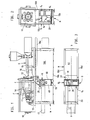
- Fig. 1,2 Die Kunststoff-Spritzgießmaschine in Seiten- und Rückansicht,
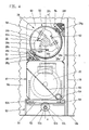
- Fig. 3 den Maschinenfuß der Kunststoff-Spritzgießmaschine gemäß Fig. 1 in Draufsicht,
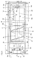
- Fig. 4 einen Ausschnitt aus dem Maschinenfuß im Bereich der die Zerkleinerungseinrichtung umfassenden Einheit(G)der Kunststoff-Spritzgießmaschine von dessen Bedienungsseite her gesehen, im Schnitt nach Linie IV-IV von Fig. 6 und in vergrößerter Darstellung,
- Fig. 5 den Ausschnitt gemäß Fig. 4 in Draufsicht,
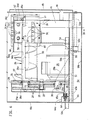
- Fig. 6 einen Schnitt nach Linie VI-VI von Fig. 5 und
- Fig. 7 die Anordnung gemäß Fig. 6 bei teilweise aus dem Maschinenfuß ausgezogener Einheit (G).
- 1.2 The plastic injection molding machine in side and rear view,
- 3 shows the machine base of the plastic injection molding machine according to FIG. 1 in plan view,
- 4 shows a detail from the machine base in the area of the unit (G) of the plastic injection molding machine comprising the size reduction device, seen from its operating side, in section along line IV-IV of FIG. 6 and in an enlarged view,
- 5 shows the detail according to FIG. 4 in plan view,
- Fig. 6 is a section along line VI-VI of Fig. 5 and
- 7 shows the arrangement according to FIG. 6 with the unit (G) partially pulled out of the machine base.
Auf dem Maschinenfuß M der Kunststoff-Spritzgießmaschine (Spritzgießmaschine) sind eine horizontale Formschließeinheit F und eine quer zur Trennebene c-c der Spritzgießform 13 arbeitende Spritzgießeinheit S angeordnet. Der stationäre Formträger 12 der Formschließeinheit F ist etwa in der Mitte des Maschinenfußes über dessen senkrecht zur Schließrichtung der Formschließeinheit F stehenden Querwand 18 angeordnet, die einen das Öl für den Hydraulikkreislauf aufnehmenden Tankraum 43 begrenzt. Der Plastifizierzylinder 16 der Spritzgießeinheit ist auf horizontalen Säulen 15, der bewegbare Formträger 11 der Formschließeinheit F auf Säulen 14 verschiebbar. Die Säulen 14 sind einenends am stationären Formträger 12 und anderenends an einer über der Rückwand des Maschinenfußes angeordneten Montageplatte 19 abgestützt welche die hydraulische Antriebseinrichtung 10 für den bewegbaren Formträger 11 trägt. Der aus Stahlblech gefertigte quaderförmige Maschinenfuß ist über dem Tankraum 43 von einem Deckel 18a und im übrigen von der Formschließeinheit F abgedeckt. Unterhalb der Spritzgießform 13 ist im Maschinenfuß M eine Vorrichtung (Separierungsvorrichtung) zum Separieren der Angüsse von den aus der Spritzgießform fallenden Spritzlingen angeordnet. Sie ist durch eine mechanische Weiche gebildet, welche eine horizontale Schwenkachse 35 und eine Platte 36 mit beidseitigen Rutschflächen umfaßt. Die beiden extremen Schwenkstellungen der Platte schließen einen Winkel von 90° ein. In der einen Endstellung bildet die Platte eine Rutsche für die ausfallenden Spritzlinge, die auf einem Förderband 17 endet, das symmetrisch zur Symmetrieebene b-b der Spritzgießmaschine angeordnet ist und diese rückseitig aus dem Maschinenfuß herausfördert. In der anderen Schwenkstellung bildet die Platte 36 eine Rutsche, die über einer als bauliche Einheit G ausgebildeten Zerkleinerungseinrichtung für die Angüsse endet. Die Zerkleinerungseinrichtung umfaßt ein mit einem Antriebsmotor 20 betriebenes Schneidwerk 28,u.eine die Angüsse zum Schneidwerk befördernde Förderschnecke 27,50.Diese ist quer zur Schließrichtung der Formschließeinheit F angeordnet und über ein Getriebe vom Antriebsmotor 20 angetrieben. Die Zerkleinerungseinrichtung umfaßt ferner einen unter dem Schneidwerk 28 angeordneten Behälter (Regeneratbehälter 41). Das Förderband 17 ist auf der von der Spritzgießeinheit S abgewandten Seite der Zerkleinerungseinrichtung angeordnet. Förderschnecke 27,50 und Schneidwerk 28 weisen eine gemeinsame Antriebswelle (Hauptwelle 26) auf. Der Antriebsmotor 20 ist parallel zur Förderschnecke 27 und unter dieser angeordnet. Förderschnecke 27, Schneidwerk 28. Regeneratbehälter 41 und Antriebsmotor 20 bilden die quaderförmige Einheit G. Die in Schließrichtung der Formschließeinheit F abgenommene Breite ist durch den Durchmesser des Antriebsmotors 20 bzw. der durch die Förderwendel 17 und das Förderrohr 50 gebildeten Förderschnecke bestimmt. Motorachse 20a und Hauptwelle 26 liegen in einer gemeinsamen vertikalen Ebene a-a. Diese Ebene a-a ist die Symmetrieebene der baulichen Einheit G. Die quaderförmige Einheit G grenzt an die den Tankraum 43 begrenzenden Querwand 18 des Maschinenfußes M an.On the machine base M of the plastic injection molding machine (injection molding machine) there are a horizontal mold closing unit F and an injection molding unit S operating transversely to the parting plane cc of the
Die dem Förderband 17 für die Spritzlinge zugewandte Breitseite der Einheit G befindet sich etwa in einer durch die Trennebene c-c der geschlossenen Spritzgießform 13 gehenden Ebene c-c. In dieser Ebene liegt etwa die horizontale Schwenkachse 35 der durch die mechanische Weiche gebildeten Separiereinrichtung.The broad side of the unit G facing the
Das tragende Skelett der baulichen Einheit G ist durch eine horizontale Basisplatte 51, eine die Getriebewellen eines Getriebes 24 aufnehmende und mit der Basisplatte 51 starr verbundene Getriebeplatte 29 und das zur Hauptwelle 26 koaxiale und an der Getriebeplatte 29 befestigte Förderrohr 50 der Förderschnecke 27,50 gebildet. Das Gehäuse des Schneidwerkes 28 ist also durch den freien Endabschnitt 50a des Förderrohres 50 der Förderschnecke 27,50 gebildet. Die Getriebeplatte 29 ist motorseitig durch Versteifungswinkel 29b abgestützt, um dieser eine ausreichende Tragfähigkeit für das Schneidwerk 28 zu verleihen. Die Vorgelegewelle 22 des das Drehmoment von der Motorachse 20a auf die Hauptwelle 26 übertragenden Getriebes 24 (mit rückseitigem Deckblech 29a) liegt in der Symmetrieebene der baulichen Einheit G. Das Schneidwerk 28 ist von zwei den Endabschnitt 50a des Förderrohres 50 umschließenden radialen Flanschen axial begrenzt. Diese sind mit dem Mantel des Förderrohres 50 fest verbunden. Der Umfang der Flansche 60,61 beschreibt etwa ein Quadrat. Die Schneidmesser 28b des Schneidwerkes 28 sind auf einem fest auf der Hauptwelle 26 sitzenden Schneidmesserträger 28a angeordnet. Dabei liegen sie auf entsprechenden Anlageflächen des Schneidmesserträgers 28a an, die tangential zur Hauptwelle 26 liegen. Mit diesen tangentialen Anlageflächen sind die Schneidmesser 28b mittels Spannschrauben 58 verspannt, die senkrecht zu diesen stehen. In der Ebene der Schneidmesser, also tangential zur Hauptwelle 26 angeordnete Stellschrauben 62 für die Schneidmesser 28b ermöglichen ein Nachstellen der Schneiden der Schneidmesser 28b. Die Stellschrauben 62 liegen mit ihren Köpfen rückseitig am zugehörigen Schneidmesser 28b an und stehen mit dem Schneidmesserträger 28a im Gewindeeingriff. In der eingestellten Position sind sie durch eine Schraubenmutter gesichert, die an einer zu den Spannschrauben 58 parallelen Schulter des Schneidmesserträgers 28a anliegt. Die Schneidmesser 28b arbeiten mit radialen Gegenschneiden 28c zusammen. Zwischen den radialen Flanschen 60,61 sind Lagerstücke 28f für die Gegenschneiden 28c angeordnet. Die Gegenschneiden 28c sind mittels Spannstücken 28g und Spannschrauben 56 mit radialen Anlageflächen der Lagerstücke 28f verspannbar, wie insbesondere aus Fig. 4 ersichtlich. Der Endabschnitt 50a des Förderrohres 50 ist mittels eines das Lager der Hauptwelle aufnehmenden Lagerflansches 63 abgeschlossen. Dieser taucht mit einem axialen Abschnitt geringeren Durchmessers zentrierend in diesen Endabschnitt 50a ein.The supporting skeleton of the structural unit G is formed by a
Aus obigem ergibt sich, daß die Hauptwelle 26 einen der Bedienungsseite der Kunststoff-Spritzgießmaschine zugewandten Endabschnitt 26e mit Lager 26d im Lagerflansch 63 aufweist, in einem rückseitig daran anschließenden Abschnitt 26b den Schneidmesserträger 28a trägt, in einem daran rückseitig anschließenden weiteren Abschnitt 26a die Förderwendel 27 aufnimmt, wobei der rückseitige (im Lager 25 aufgenommenen) Endabschnitt 26c die Abtriebswelle des Getriebes 24 bildet. Das Förderrohr 50 weist im Eingangsabschnitt einen als Einfallöffnung für das zu verkleinernde Kunststoffmaterial dienenden Ausschnitt 50b auf.It follows from the above that the
Im Endabschnitt 50a ist das Förderrohr 50 mit einem als Ausfallöffnung für das zerkleinerte Kunststoffmaterial versehen. Er erstreckt sich zwichen den diametralen Gegenschneiden 28c über einen Zentriwinkel von 180°. Dieser Ausschnitt 50c ist von einem Sieb 28e abgedeckt, das radiale Sieblöcher 28eʹ aufweist. Das Sieb 28e ist über radial abgebogene Ränder mittels tangentialer Spannschrauben 57 und mittels der Spannstücke 28g mit den Lagerstücken 28f verspannt. Das durch das Sieb 28e fallende zerkleinerte Kunststoffmaterial ist über ein zur Vertikalen geneigtes Leitblech 55 und einem die Rückwand des Regeneratbehälters 41 durchsetzenden Saugstutzen 54 zuleitbar. Dieser ist über ein koaxiales Zwischenstück 54b und eine die Rückwand 18c des Maschinenfußes M durchsetzenden Anschlußstutzen 54a mit einem das Kunststoffmaterial abführenden Saugrohr verbunden, welch letzteres zeichnerisch nicht dargestellt ist.In the
Wie insbesondere aus den Fign. 2 und 3 ersichtlich, ist die bauliche Einheit G somit in einem Antriebsteil G1, einen Getriebeteil G2, einen Förderteil G3 und ein Schneidwerkteil G4 sowie einen Behälterteil G5 gegliedert. Die bauliche Einheit G ist mittels Laufrollen 59 im Führungsteil 52A eines mit dem Maschinenfuß M verbundenen Sockels 52 quer zur Schließrichtung der Formschließeinheit F aus dem Maschinenfuß M (mit Boden 18b) herausziehbar. Zu diesem Zweck sind Laufrollen 59 an den Längsseiten der Basisplatte 51 gelagert. Im Maschinenfuß M ist die bauliche Einheit G mit Hilfe einer Verriegelungseinrichtung 53 in Arbeitsposition arretierbar. Diese Verriegelungseinrichtung 53 umfaßt einen als Riegel dienenden Exzenter 53c, der auf einer in der Symmetrieebene a-a liegenden Welle 53b des Sockels 52 fest aufsitzt. Durch Drehung der Welle 53b (mittels Innensechskant 53a) ist der Exzenter 53c in einen korrespondierenden Ausschnitt 51a der Basisplatte in Arretierposition einsteuerbar. Die Abmessungen und die Anordnung des Exzenters 53c ist derart, daß dieser in Arretierposition die Basisplatte 51 zur axialen Arretierung der Einheit G nach oben, also gegen die Rollenführungen des Führungsteiles 52A drückt. Ein elektrischer Anschluß für den Antriebsmotor 20 ist durch die Einschubbewegung bzw. Ausziehbewegung der Einheit G herstellbar bzw. Aufhebbar. Der eine Kontaktteil 64 des Anschlusses ist an der Rückwand 18c des Maschinenfußes M und der andere Kontaktteil 65 an der Basisplatte 51 befestigt. Zur Befestigung des Kontaktteiles 64 dient ein mit der Rückwand 18c verschraubtes Winkelblech 64a, zur Befestigung des Kontaktteiles 65 ein mit der Basisplatte verschraubtes Winkelblech 65b, wobei dieses Kontaktteil 65 mit Hilfe von Schraubenfedern 65a am vertikalen Schenkel des Winkelbleches 65b federnd gelagert ist, wie insbesondere aus den Fign. 6,7 ersichtlich. Ein dem Seitenriß der baulichen Einheit G entsprechender Ausschnitt aus der bedienungsseitigen Wand 18d des Maschinenfußes M ist mit Hilfe einer Tür 45 abschließbar. Ein an der Türe 45 angeordneter Sicherheitsschalter 46 beherrscht den Stromkreis des Antriebsmotors 20, indem er beim Öffnen bzw. Schließen der Türe 45 den Sicherheitsschalter 46 betätigt und dadurch den Stromkreis des Antriebsmotors trennt bzw. schließt.As in particular from FIGS. 2 and 3, the structural unit G is thus divided into a drive part G1, a gear part G2, a conveying part G3 and a cutting part G4 and a container part G5. The structural unit G can be pulled out of the machine base M (with
Die in der baulichen Einheit G angeordnete Zerkleinerungseinrichtung und die mechanische Weiche (Schwenkachse 35 und Platte 36) sind vom zentralen Rechner der Kunststoff-Spritzgießmaschine derart steuerbar, daß unbrauchbare Spritzlinge, die von diesem Rechner durch den fehlerhaften Ablauf eines Fertigungsparameters erkannt sind, unmittelbar in die Zerkleinerungseinrichtung geleitet werden. Der unter dem Schneidwerk auf der Basisplatte 51 abgestellte Regeneratbehälter 41 ist als ausziehbare Schublade mit Handgriff ausgebildet. Er ist daher auch manuell entleerbar, wobei in diesem Falle das Leitblech 55 zweckmäßigerweise aus dem Regeneratbehälter 41 herausgenommen wird.The comminution device arranged in the structural unit G and the mechanical switch (
Claims (24)
Applications Claiming Priority (2)
| Application Number | Priority Date | Filing Date | Title |
|---|---|---|---|
| DE19863637612 DE3637612A1 (en) | 1986-11-05 | 1986-11-05 | PLASTIC INJECTION MOLDING MACHINE WITH BUILT-IN CRUSHING DEVICE FOR THE CASTING |
| DE3637612 | 1986-11-05 |
Publications (2)
| Publication Number | Publication Date |
|---|---|
| EP0266584A2 true EP0266584A2 (en) | 1988-05-11 |
| EP0266584A3 EP0266584A3 (en) | 1989-08-09 |
Family
ID=6313180
Family Applications (1)
| Application Number | Title | Priority Date | Filing Date |
|---|---|---|---|
| EP87114896A Withdrawn EP0266584A3 (en) | 1986-11-05 | 1987-10-13 | Plastic injection-moulding machine with a built-in comminution apparatus for sprues |
Country Status (4)
| Country | Link |
|---|---|
| US (1) | US4883418A (en) |
| EP (1) | EP0266584A3 (en) |
| JP (1) | JPS63188015A (en) |
| DE (1) | DE3637612A1 (en) |
Cited By (3)
| Publication number | Priority date | Publication date | Assignee | Title |
|---|---|---|---|---|
| WO1998026873A1 (en) * | 1996-12-19 | 1998-06-25 | Nuga Ag | Blade mill for grinding plastic material |
| US7021576B2 (en) | 2003-06-19 | 2006-04-04 | Nuga AG Kunststoffschneidemühlen | Blade mill for grinding plastic material |
| CN103770272A (en) * | 2014-01-09 | 2014-05-07 | 苏州工业园区协利塑胶有限公司 | Distribution mechanism applicable to production of injection molding parts |
Families Citing this family (10)
| Publication number | Priority date | Publication date | Assignee | Title |
|---|---|---|---|---|
| DE3831129A1 (en) * | 1988-09-13 | 1990-03-22 | Karl Hehl | INJECTION MOLDING MACHINE WITH DEVICE FOR SEPARATING NON-USEABLE INJECTION PARTS OR. OF POOL PARTS |
| US5090628A (en) * | 1990-02-06 | 1992-02-25 | Sierra Machinery, Inc. | Chip crusher |
| DE19961882A1 (en) * | 1999-12-20 | 2001-06-28 | Getecha Ges Fuer Tech Anlagen | Comminuter for plastics has a rugged, simple integral sieve and stator |
| FR2855436B1 (en) * | 2003-05-26 | 2006-03-17 | Martiplast | SORTING DEVICE FOR INDUSTRIAL MACHINE |
| US7455083B2 (en) * | 2004-09-07 | 2008-11-25 | Gerald Schlaf | Accumulator for gaseous systems |
| CN101306569B (en) * | 2007-05-16 | 2011-03-23 | 鸿富锦精密工业(深圳)有限公司 | Mold device and injection molding method |
| JP6426651B2 (en) * | 2016-04-14 | 2018-11-21 | ファナック株式会社 | Injection molding system for assembly work in the mold |
| JP7223152B2 (en) * | 2019-03-01 | 2023-02-15 | キヤノンバージニア, インコーポレイテッド | Injection molding system with transport device for inserting or ejecting the mold |
| US20220161471A1 (en) * | 2019-04-11 | 2022-05-26 | Canon Virginia, Inc. | Injection molding system with conveyor devices to insert or eject molds |
| CN113524562B (en) * | 2021-09-16 | 2021-12-03 | 佛山昱希汽车科技有限公司 | Car atmosphere light conductor device of moulding plastics |
Citations (6)
| Publication number | Priority date | Publication date | Assignee | Title |
|---|---|---|---|---|
| DE1053291B (en) * | 1955-12-07 | 1959-03-19 | J F Bas & Cie S A | Cutting mill with knives arranged on the rotor and on the stator |
| DE2021660A1 (en) * | 1969-05-05 | 1970-11-19 | Hobart Mfg Co | Food blender |
| US3566444A (en) * | 1968-05-27 | 1971-03-02 | Husky Mfg Tool Works Ltd | Scrap grinder for injection-molding machine |
| US3860182A (en) * | 1973-11-05 | 1975-01-14 | Cumberland Eng Co | Auger feed granulator |
| US4321027A (en) * | 1979-06-18 | 1982-03-23 | Leesona Corporation | Under the press granulator construction |
| FR2516856A1 (en) * | 1981-11-20 | 1983-05-27 | Hehl Karl | DEVICE FOR UNLOADING AN INJECTION MOLDING PRESS |
Family Cites Families (10)
| Publication number | Priority date | Publication date | Assignee | Title |
|---|---|---|---|---|
| US3407444A (en) * | 1966-05-19 | 1968-10-29 | Husky Mfg Tool Works Ltd | Injection molding machine with scrap grinder |
| US3418694A (en) * | 1966-09-30 | 1968-12-31 | Pennsalt Chemicals Corp | Apparatus scrap grinder and plastic injection molding machine |
| US3672803A (en) * | 1970-05-13 | 1972-06-27 | Husky Mfg Tool Works Ltd | Scrap grinder for injection-molding machine |
| US3776675A (en) * | 1970-09-18 | 1973-12-04 | Olivetti & Co Spa | Injection moulding press with means for separating scrap material from the molded articles |
| DE3242169C2 (en) * | 1982-06-18 | 1984-07-19 | Karl 7298 Loßburg Hehl | Horizontal mold clamping unit of a plastic injection molding machine with mold changing device |
| FR2534180A1 (en) * | 1982-10-12 | 1984-04-13 | Clayton Cie | Screw-feed grinder for plastic recovered from moulding, especially intended for an injection press. |
| DD222505A1 (en) * | 1983-12-27 | 1985-05-22 | Plast Elastverarb Ingbetrieb | CUTTING GRINDERS FOR GRINDING ANIMALS |
| GB2157249B (en) * | 1984-03-08 | 1987-08-19 | Karl Hehl | A conveyor means |
| FR2567420A1 (en) * | 1984-07-11 | 1986-01-17 | Clayton Cie | Screw-fed grinding mill of reduced height |
| US4737095A (en) * | 1986-05-21 | 1988-04-12 | Karl Hehl | Component changing apparatus serving a group of injection molding machines |
-
1986
- 1986-11-05 DE DE19863637612 patent/DE3637612A1/en not_active Withdrawn
-
1987
- 1987-10-13 EP EP87114896A patent/EP0266584A3/en not_active Withdrawn
- 1987-11-02 JP JP62275928A patent/JPS63188015A/en active Granted
-
1988
- 1988-10-03 US US07/252,124 patent/US4883418A/en not_active Expired - Fee Related
Patent Citations (6)
| Publication number | Priority date | Publication date | Assignee | Title |
|---|---|---|---|---|
| DE1053291B (en) * | 1955-12-07 | 1959-03-19 | J F Bas & Cie S A | Cutting mill with knives arranged on the rotor and on the stator |
| US3566444A (en) * | 1968-05-27 | 1971-03-02 | Husky Mfg Tool Works Ltd | Scrap grinder for injection-molding machine |
| DE2021660A1 (en) * | 1969-05-05 | 1970-11-19 | Hobart Mfg Co | Food blender |
| US3860182A (en) * | 1973-11-05 | 1975-01-14 | Cumberland Eng Co | Auger feed granulator |
| US4321027A (en) * | 1979-06-18 | 1982-03-23 | Leesona Corporation | Under the press granulator construction |
| FR2516856A1 (en) * | 1981-11-20 | 1983-05-27 | Hehl Karl | DEVICE FOR UNLOADING AN INJECTION MOLDING PRESS |
Cited By (4)
| Publication number | Priority date | Publication date | Assignee | Title |
|---|---|---|---|---|
| WO1998026873A1 (en) * | 1996-12-19 | 1998-06-25 | Nuga Ag | Blade mill for grinding plastic material |
| US7021576B2 (en) | 2003-06-19 | 2006-04-04 | Nuga AG Kunststoffschneidemühlen | Blade mill for grinding plastic material |
| CN103770272A (en) * | 2014-01-09 | 2014-05-07 | 苏州工业园区协利塑胶有限公司 | Distribution mechanism applicable to production of injection molding parts |
| CN103770272B (en) * | 2014-01-09 | 2016-02-03 | 苏州工业园区协利塑胶有限公司 | Be applied to the feeding distribution mechanism that injection-moulded plastic part is produced |
Also Published As
| Publication number | Publication date |
|---|---|
| JPS63188015A (en) | 1988-08-03 |
| US4883418A (en) | 1989-11-28 |
| JPH0343047B2 (en) | 1991-07-01 |
| DE3637612A1 (en) | 1988-05-19 |
| EP0266584A3 (en) | 1989-08-09 |
Similar Documents
| Publication | Publication Date | Title |
|---|---|---|
| EP0612559B1 (en) | Extrusions machine | |
| EP2704838B1 (en) | Device for the impact crushing and dispensing of materials, in particular wood, in several fractions | |
| EP0266584A2 (en) | Plastic injection-moulding machine with a built-in comminution apparatus for sprues | |
| EP3689561B1 (en) | Device for processing flat objects | |
| EP0632961B1 (en) | Conche | |
| DE4410577A1 (en) | Device for processing sheet material or the like | |
| EP2556920B1 (en) | Device for sharpening knives of a knife ring for a knife ring flaker | |
| DE2256524A1 (en) | PROCESS AND DEVICE FOR CRUSHING GOOD IN SMALL PIECES | |
| DE2836847A1 (en) | LOW-VOLUME MULTI-WAVE SCREW MACHINE OUTLET DEVICE WITH SCREEN EXCHANGE DEVICE | |
| DE2516111C2 (en) | Shredding device, in particular for processing paper and plastic material | |
| DE2451785A1 (en) | PLANING MACHINE | |
| DE4105473C1 (en) | ||
| EP0917911B1 (en) | Screening device | |
| DE4433473A1 (en) | Granulator for plastics material | |
| EP0688657A1 (en) | Die changer for extruder | |
| EP1495685B1 (en) | Apparatus for making rod-shaped tobacco products, particularly filter cigarettes | |
| EP0359012B1 (en) | Plastic injection-moulding machine with a separator for eliminating useless mouldings | |
| EP0256241A2 (en) | Apparatus for grinding organic materials | |
| EP0383226A1 (en) | Screw press, in particular for comminuting materials such as organic wastes or the like | |
| EP0884105A1 (en) | Feeding, supporting, bearing and mounting means for comminuting machines | |
| DE3918729A1 (en) | DEVICE FOR CRUSHING PLASTIC PARTS, ESPECIALLY FOAMED PLASTIC, SUCH AS FOAM | |
| DE3645146C2 (en) | Sepg. and cutting plastic dead heads from moulding | |
| EP0956172A1 (en) | Pressing device for compressing metal parts, in particular chips | |
| DE3123484C2 (en) | Shredding device for fibrous material | |
| DE10009703A1 (en) | Food chopper comprises conveyor, cutter unit of two adjacent cutters with rotary blades and set of circular blades, counter-bar, and stop |
Legal Events
| Date | Code | Title | Description |
|---|---|---|---|
| PUAI | Public reference made under article 153(3) epc to a published international application that has entered the european phase |
Free format text: ORIGINAL CODE: 0009012 |
|
| AK | Designated contracting states |
Kind code of ref document: A2 Designated state(s): AT CH DE FR GB IT LI NL |
|
| PUAL | Search report despatched |
Free format text: ORIGINAL CODE: 0009013 |
|
| AK | Designated contracting states |
Kind code of ref document: A3 Designated state(s): AT CH DE FR GB IT LI NL |
|
| STAA | Information on the status of an ep patent application or granted ep patent |
Free format text: STATUS: THE APPLICATION HAS BEEN WITHDRAWN |
|
| 18W | Application withdrawn |
Withdrawal date: 19890830 |