EP0265883A2 - Drehschalter - Google Patents
Drehschalter Download PDFInfo
- Publication number
- EP0265883A2 EP0265883A2 EP19870115657 EP87115657A EP0265883A2 EP 0265883 A2 EP0265883 A2 EP 0265883A2 EP 19870115657 EP19870115657 EP 19870115657 EP 87115657 A EP87115657 A EP 87115657A EP 0265883 A2 EP0265883 A2 EP 0265883A2
- Authority
- EP
- European Patent Office
- Prior art keywords
- rotor
- rotary switch
- switch according
- stator
- side wall
- Prior art date
- Legal status (The legal status is an assumption and is not a legal conclusion. Google has not performed a legal analysis and makes no representation as to the accuracy of the status listed.)
- Granted
Links
Images

Classifications
-
- H—ELECTRICITY
- H01—ELECTRIC ELEMENTS
- H01H—ELECTRIC SWITCHES; RELAYS; SELECTORS; EMERGENCY PROTECTIVE DEVICES
- H01H19/00—Switches operated by an operating part which is rotatable about a longitudinal axis thereof and which is acted upon directly by a solid body external to the switch, e.g. by a hand
- H01H19/54—Switches operated by an operating part which is rotatable about a longitudinal axis thereof and which is acted upon directly by a solid body external to the switch, e.g. by a hand the operating part having at least five or an unspecified number of operative positions
- H01H19/56—Angularly-movable actuating part carrying contacts, e.g. drum switch
- H01H19/58—Angularly-movable actuating part carrying contacts, e.g. drum switch having only axial contact pressure, e.g. disc switch, wafer switch
- H01H19/585—Angularly-movable actuating part carrying contacts, e.g. drum switch having only axial contact pressure, e.g. disc switch, wafer switch provided with printed circuit contacts
-
- G—PHYSICS
- G05—CONTROLLING; REGULATING
- G05G—CONTROL DEVICES OR SYSTEMS INSOFAR AS CHARACTERISED BY MECHANICAL FEATURES ONLY
- G05G25/00—Other details or appurtenances of control mechanisms, e.g. supporting intermediate members elastically
- G05G25/04—Sealing against entry of dust, weather or the like
-
- G—PHYSICS
- G05—CONTROLLING; REGULATING
- G05G—CONTROL DEVICES OR SYSTEMS INSOFAR AS CHARACTERISED BY MECHANICAL FEATURES ONLY
- G05G1/00—Controlling members, e.g. knobs or handles; Assemblies or arrangements thereof; Indicating position of controlling members
- G05G1/08—Controlling members for hand actuation by rotary movement, e.g. hand wheels
-
- H—ELECTRICITY
- H01—ELECTRIC ELEMENTS
- H01H—ELECTRIC SWITCHES; RELAYS; SELECTORS; EMERGENCY PROTECTIVE DEVICES
- H01H19/00—Switches operated by an operating part which is rotatable about a longitudinal axis thereof and which is acted upon directly by a solid body external to the switch, e.g. by a hand
- H01H19/02—Details
- H01H19/10—Movable parts; Contacts mounted thereon
- H01H19/11—Movable parts; Contacts mounted thereon with indexing means
-
- H—ELECTRICITY
- H01—ELECTRIC ELEMENTS
- H01H—ELECTRIC SWITCHES; RELAYS; SELECTORS; EMERGENCY PROTECTIVE DEVICES
- H01H25/00—Switches with compound movement of handle or other operating part
- H01H25/06—Operating part movable both angularly and rectilinearly, the rectilinear movement being along the axis of angular movement
-
- H—ELECTRICITY
- H01—ELECTRIC ELEMENTS
- H01H—ELECTRIC SWITCHES; RELAYS; SELECTORS; EMERGENCY PROTECTIVE DEVICES
- H01H3/00—Mechanisms for operating contacts
- H01H3/02—Operating parts, i.e. for operating driving mechanism by a mechanical force external to the switch
- H01H3/20—Operating parts, i.e. for operating driving mechanism by a mechanical force external to the switch wherein an auxiliary movement thereof, or of an attachment thereto, is necessary before the main movement is possible or effective, e.g. for unlatching, for coupling
Definitions
- the present invention relates to a rotary switch according to the preamble of claim 1.
- Such rotary switches are known as so-called rotary switches.
- the structure is similar to that described in DE-AS 26 59 084 or DE-OS 23 56 500.
- the actuation button rests on the stator, which is larger in diameter, whereas in the case of the knob rotary switches, this also overlaps the stator, which is somewhat smaller in diameter, on the side edges.
- a so-called rotary knob switch is to be designed so that it is watertight, in particular watertight.
- stator 4 with a rotary switch is referred to, which consists of a stator 4 and a pot-shaped overlapping rotor 5.
- the stator 4 has a disk-shaped support flange 7 and a shaft 3.
- the latter is expediently designed as a screw attachment, which can be inserted into a front plate 2 (for example a device which is watertight against water pressure) and can be screwed onto it by means of a nut 6.
- the bottom 8 lies on the top 9 of the front panel.
- the rotor 5 is also designed as an operating button.
- a circumferential groove 13 is provided in the peripheral wall 12 of the support flange 7, in which an elastic sealing ring 14 is also inserted. The latter protrudes beyond the peripheral wall 12.
- the inner wall 15 of the support flange 7 overlapping side wall 16 of the rotor 5 is so small from the peripheral wall 12 of the support flange 7 that it presses against the sealing ring 14 and thus a water-tight seal between the inner wall 15 and the peripheral wall 12 is achieved.
- the inner wall 15 slides on the sealing ring 14 when the rotor 5 is rotated.
- a lubricant is expediently provided between the inner wall 15 and the sealing ring 14.
- the two sealing rings 11 and 14 achieve a completely tight switch and a seal from the switch to the inside of a device.
- the shaft 3 and the support flange 7 can be made of metal.
- the shaft 3 then has a bore 18 into which a mushroom-shaped contact carrier 19 made of insulating material with its axis extension 20 is inserted.
- the attachment is made by Screwing, gluing, pressing or shrinking the stator 4 onto the axle extension 20 in such a way that a connection which is watertight is created.
- a transverse bore 21 (FIG. 1) or a groove 22 (FIG. 2) is provided which, in the case of a two-part design, is provided either in the support flange 7 or in the insulating contact carrier 19 and in which a compression spring 23 and a detent ball 24 are guided .
- the latter snaps in a manner known per se with a locking ring 25 on the inner wall 15 of the side wall 16 of the rotor 5.
- the transverse bore 21 or groove 22 can also be provided in the rotor 5 and the locking ball 24 can then press against the end wall 57 of a stator part 58, which carries a locking ring 25 (see. Fig. 5).
- stator 4 is made of insulating material or if an insulating contact carrier 19 is used, fixed contact connections 26 are formed in the shaft 3 or the axle extension 20, which are connected to fixed contacts 28 accessible on the surface 27, or the fixed contact connections 26 and the fixed contacts 28 are formed as an angled unit .
- the movable contacts 29 are attached to the inside 30 of the rotor cover 31 and can e.g. Connect a center contact 28.1 and an external contact 28.2.
- the rotor 5 is fastened according to FIG. 3 in that a ring 33 is glued to the lower edge 32 of the side wall 16 with an inwardly extending ring flange 34 sliding on the support flange 7.
- the annular flange 34 expediently engages in an annular recess 35 in the support flange 7.
- a protruding edge of the side wall 16 of the rotor 5 can also be formed inwards by hot deformation, and the ring flange 34 can thus be formed.
- a retaining ring disk 37 can be attached to the edge 36 of the rotor 5 and can be fastened, for example, by means of hot deformation of protruding edge parts 59.
- the retaining ring disk 37 can advantageously be designed as a coding disk in that it is provided with at least one stop which can come into operative connection with at least one counter-stop of the support flange 7.
- a locking cam 38 can be formed by means of at least one resilient intermediate member 39, which is advantageously designed as a spring leg.
- a switch is described in which the retaining ring disk 37 is designed as a coding disk and the rotor 5 can be pulled up from the stator 4 by a small stroke.
- a stop 40 of the rotor 5 can be disengaged from a shoulder 41 of the stator 4, so that the rotor 5 can be rotated even further if the stop is overcome after the rotor 5 has been lifted.
- the stop 40 can also be provided on the retaining ring disk 37.
- the stator 4 then has an extension 41.1 in its area.
- the rotor 5 can also be fastened according to FIG. 12 by means of an axis 42 formed on it, which is inserted from one side through a bore 43 in the contact carrier 19 and screwed on the other side.
- a rotary pull switch in a pressure-water-tight design can also be produced, as shown in FIG. 13.
- the bore 43 in the contact carrier 19 has an extension 44 for inserting a compression spring 45, which between the Stator stop 46 and a washer 47 is clamped. The latter is held by a screw 48 which can be screwed into the axis 42 from below.
- a rotor head 50 is connected to the rotor 5, optionally with the interposition of a spring washer or sliding washer 49, by means of positive locking for rotary movements and sliding fit for axial movements (pull) of the rotor 5.
- a shoulder 41 cf. FIGS. 10 and 11
- the stator 4 which limits the rotary movement of the rotor 5 can be overcome, so that the rotor 5 can be rotated even further.
- the rotor head 50 is replaced by e.g. reshaped segments 52 held.
- the rotor head 50 contains the movable contacts 29, which are pressed onto the fixed contacts 28 by means of a spring and are designed as a rocker switch Support surface 53 is preferably attached in a watertight manner by gluing or pressing.
- the thread overlap area 55 of the nut 6 required for fastening the switch can be accommodated for the most part within the thickness of the front plate 2.
Landscapes
- Physics & Mathematics (AREA)
- General Physics & Mathematics (AREA)
- Engineering & Computer Science (AREA)
- Automation & Control Theory (AREA)
- Rotary Switch, Piano Key Switch, And Lever Switch (AREA)
- Switches With Compound Operations (AREA)
- Push-Button Switches (AREA)
Abstract
Description
- Die vorliegende Erfindung bezieht sich auf einen Drehschalter gemäß dem Oberbegriff des Anspruchs 1.
- Derartige Drehschalter sind als sogenannte Knopf-Drehschalter bekannt. Der Aufbau ist denen ähnlich wie er in der DE-AS 26 59 084 oder der DE-OS 23 56 500 beschrieben ist. Dort liegt jedoch der Betätigungsknopf auf dem im Durchmesser größeren Stator auf, wogegen bei den Knopf-Drehschaltern dieser den im Durchmesser etwas kleineren Stator auch an den Seitenkanten noch übergreift.
- Mit der vorliegenden Erfindung soll ein sogenannter Knopf-Drehschalter so ausgebildet werden, daß er wasserdicht, insbesondere druckwasserdicht ist.
- Diese Aufgabe wird durch die im Kennzeichen des Anspruchs 1 angegebenen Merkmale gelöst. Hierdurch wird nicht nur eine wasserdichte Ausführung des Schalters selbst erreicht, sondern auch das Eindringen von Wasser zwischen Schalter und Einbauplatte vermieden, so daß kein Wasser in ein Gerät über den Schalter bzw. die Schalteranordnung eindringen kann.
- Weitere vorteilhafte Einzelheiten der Erfindung sind in den Unteransprüchen angegeben und nachfolgend anhand der in den Zeichnungen veranschaulichten Ausführungsbeispiele beschrieben. Es zeigen:
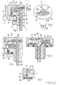
- Fig. 1 die eine Hälfte eines Drehschalters von der Seite im Schnitt,
- Fig. 2 den zugehörigen Stator in perspektivischer Ansicht,
- Fig. 3 ein anderes Ausführungsbeispiel mit einer Betätigungsknopfhalterung,
- Fig. 4 einen Ausschnitt einer Variante der Betätigungsknopfhalterung,
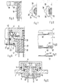
- Fig. 5 einen Schalter mit einem anderen Rastwerk von der Seite im Schnitt, die
- Fig. 6 bis 8 ein Ausführungsmöglichkeit der Rotarrastung die
- Fig. 9 bis 11 ein Ausführungsbeispiel mit winem als Kodierer ausgebildeten Halterand,
- Fig. 12 eine Ausführungsform der Betätigungsknopfbefestigung und
- Fig. 13 einen kombinierten Dreh-Zugschalter.
- Mit 1 ist ein Drehschalter bezeichnet, der aus einem Stator 4 und einem diesen topfförmig übergreifenden Rotor 5 besteht. Der Stator 4 besitzt einen scheibenförmigen Auflageflansch 7 und einen Schaft 3. Letzterer ist zweckmäßig als Schraubansatz ausgebildet, der in eine Frontplatte 2 (z.B. eines druckwasserdichten Gerätes) einsetzbar und an dieser mittels einer Mutter 6 anschraubbar ist. Dabei liegt die Unterseite 8 auf der Oberseite 9 der frontplatte auf. Der Rotor 5 ist zugleich als Betätigungsknopf ausgebildet.
- Auf der Unterseite 8 des Auflageflansches 7 ist eine Ringnut 10 angebracht, in die ein elastischer Dichtungsring 11 eingelegt ist, der über die Unterseite 8 übersteht und beim Anziehen der Mutter 6 zwischen Stator 4 und Frontplatte 2 einen wasserdichten, insbesondere druckwasserdichten Abschluß bewirkt.
- In der Umfangswandung 12 des Auflageflansches 7 ist eine umlaufende Nut 13 vorgesehen, in der ebenfalls ein elastischer Dichtungsring 14 eingesetzt ist. Letzterer steht über die Umfangswandung 12 vor. Die Innenwand 15 der den Auflageflansch 7 übergreifenden Seitenwand 16 des Rotors 5 ist so gering von der Umfangswandung 12 des Auflageflansches 7 entfernt, daß sie gegen den Dichtungsring 14 drückt und so ein druckwasserdichter Abschluß zwischen der Innenwand 15 und der Umfangswandung 12 erreicht wird. Dabei gleitet die Innenwand 15 beim Drehen des Rotors 5 auf dem Dichtring 14. Zweckmäßig ist zwischen Innenwand 15 und Dichtring 14 ein Schmiermittel vorgesehen. Durch die beiden Dichtungsringe 11 und 14 wird ein vollkommen dichter Schalter und eine Abdichtung vom Schalter zum Inneren eines Gerätes erreicht.
- Zur Erhöhung der Festigkeit kann der Schaft 3 und auch der Auflageflansch 7 aus Metall bestehen. Der Schaft 3 besitzt dann eine Bohrung 18, in die ein pilzförmiger Kontaktträger 19 aus Isoliermaterial mit seinem Achsansatz 20 eingesetzt ist. Die Befestigung erfolgt durch Verschraubung, Verklebung, Einpressen oder Aufschrumpfen des Stators 4 auf den Achsansatz 20 derart, daß eine druckwasserdichte Verbindung entsteht.
- Im Stator 4 ist eine Querbohrung 21 (Fig. 1) oder eine Nut 22 (Fig. 2) vorgesehen, die bei zweiteiliger Ausführung entweder im Auflageflansch 7 oder im isolierenden Kontaktträger 19 angebracht ist und in der eine Druckfeder 23 und eine Rastkugel 24 geführt ist. Letztere rastet in an sich bekannter Weise mit einem Rastkranz 25 auf der Innenwand 15 der Seitenwand 16 des Rotors 5. Die Querbohrung 21 oder Nut 22 kann auch im Rotor 5 vorgesehen sein und die Rastkugel 24 kann dann gegen die Stirnwand 57 eines Statorteils 58 drücken, der einen Rastkranz 25 trägt (vgl. Fig. 5).
- Bei aus Isolierstoff bestehendem Stator 4 oder Verwendung eines isolierenden Kontaktträgers 19 sind in den Schaft 3 bzw. den Achsansatz 20 Festkontaktanschlüsse 26 eingeformt, die mit an der Oberfläche 27 zugänglichen Festkontakten 28 verbunden sind oder die Festkontaktanschlüsse 26 und die Festkontakte 28 sind als abgewinkelte Einheit eingeformt.
- Die beweglichen Kontakte 29 sind an der Innenseite 30 des Rotordeckels 31 angebracht und können z.B. einen Mittenkontakt 28.1 und einen Außenkontakt 28.2 verbinden.
- Die Befestigung des Rotors 5 erfolgt gemäß Fig. 3 dadurch, daß an den unteren Rand 32 der Seitenwand 16 ein Ring 33 mit einem nach innen reichenden, auf dem Auflageflansch 7 gleitenden Ringflansch 34 angeklebt ist. Der Ringflansch 34 greift zweckmäßig in eine ringförmige Aussparung 35 des Auflageflansches 7 ein. Anstelle eines angeklebten Ringes 33 kann auch ein überstehender Rand der Seitenwand 16 des Rotors 5 durch Warmverformung nach innen geformt sein und so der Ringflansch 34 gebildet werden.
- Weiterhin kann anstelle des genannten Ringes 33 oder des überstehenden Randes gemäß Fig. 4 am Rand 36 des Rotors 5 eine Halteringscheibe 37 angebracht und beispielsweise durch Warmverformung überstehender Randteile 59 befestigt sein. Vorteilhaft kann die Halteringscheibe 37 als Kodierscheibe ausgebildet sein, indem sie mit wenigstens einem Anschlag versehen ist, der mit wenigstens einem Gegenanschlag des Auflageflansches 7 in Wirkverbindung kommen kann.
- Gemäß einer in den Fig. 6 bis 8 dargestellten vorteilhaften Ausgestaltung der Erfindung kann anstelle der Verwendung einer Rastkugel 24 am Kontaktträger 19 oder am Rotor 5 ein Rastnocken 38 mittels wenigstens eines federnden, vorteilhaft als Federschenkel ausgebildeten Zwischengliedes 39 angeformt sein.
- In den Fig. 9 bis 11 ist ein Schalter beschrieben, bei dem die Halteringscheibe 37 als Kodierscheibe ausgebildet ist und der Rotor 5 um einen geringen Hub vom Stator 4 hochziehbar ist. Beim Hochziehen kann eine Ausrastung eines Anschlages 40 des Rotors 5 von einem Ansatz 41 des Stators 4 erfolgen, so daß der Rotor 5 noch weiter gedreht werden kann, wenn nach Hochheben des Rotors 5 der Anschlag überwunden ist. Der Anschlag 40 kann auch an der Halteringscheibe 37 vorgesehen sein. Der Stator 4 besitzt dann in dessen Bereich einen Ansatz 41.1.
- Die Befestigung des Rotors 5 kann auch gemäß Fig. 12 mittels einer an ihm angeformten Achse 42 erfolgen, die von einer Seite aus durch eine Bohrung 43 des Kontaktträgers 19 hindurchgesteckt und auf der anderen Seite verschraubt ist. Auf diese Weise kann auch ein Zug-Drehschalter in druckwasserdichter Ausführung erstellt werden, wie in Fig. 13 dargestellt. Die Bohrung 43 im Kontaktträger 19 besitzt hier noch eine Erweiterung 44 zum Einsetzen einer Druckfeder 45, die zwischen dem Statoranschlag 46 und einer Unterlegscheibe 47 eingespannt ist. Letztere ist durch eine in die Achse 42 von unten einschraubbare Schraube 48 gehalten.
- Mit dem Rotor 5 ist, gegebenenfalls unter Zwischenlage einer Federscheibe oder Gleitscheibe 49, ein Rotorkopf 50 mittels Formschluß für Drehbewegungen und Gleitsitz für axiale Bewegungen (Zug) des Rotors 5 verbunden. Beim Hochziehen des Rotors 5 um den Hub 54 kann beispielsweise ein die Drehbewegung des Rotors 5 begrenzender Ansatz 41 (vgl. Fig. 10 und 11) des Stators 4 überwunden werden, so daß der Rotor 5 noch weiter gedreht werden kann. Beim Hochziehen des Rotors 5 wird der Rotorkopf 50 durch die am Stator 4 vorgesehenen z.B. umgeformten Segmente 52 gehalten. Im Rotorkopf 50 befinden sich die mittels einer Feder an die Festkontakte 28 angedrückten, als Schaltwippe ausgebildeten beweglichen Kontakte 29. Der Kontaktträger 19 ist über eine Rastnase 51 zum Stator 4 lageorientiert und mit seinem Achsansatz 20 im Bereich der Bohrung 18 und/oder im Bereich der Auflagefläche 53 vorzugsweise durch Klebung oder Pressung wasserdicht befestigt. Zur Erzielung eines möglichst geringen Überstandsmaßes 56 zur Innenkante der Frontplatte 2 kann der für die Befestigung des Schalters notwendige Gewindeüberdeckungsbereich 55 der Mutter 6 zum Großteil innerhalb der Dicke der Frontplatte 2 untergebracht werden.
- Bei einem um den Hub 54 abziehbaren Rotor 5 ist der Rand 36 seiner Seitenwand 16 so weit nach unten gezogen, daß er auch in abgezogener Stellung noch den Dichtring 14 überdeckt.
Claims (21)
Priority Applications (1)
| Application Number | Priority Date | Filing Date | Title |
|---|---|---|---|
| AT87115657T ATE86786T1 (de) | 1986-10-28 | 1987-10-26 | Drehschalter. |
Applications Claiming Priority (2)
| Application Number | Priority Date | Filing Date | Title |
|---|---|---|---|
| DE19863636575 DE3636575A1 (de) | 1986-10-28 | 1986-10-28 | Drehschalter |
| DE3636575 | 1986-10-28 |
Publications (3)
| Publication Number | Publication Date |
|---|---|
| EP0265883A2 true EP0265883A2 (de) | 1988-05-04 |
| EP0265883A3 EP0265883A3 (en) | 1989-10-18 |
| EP0265883B1 EP0265883B1 (de) | 1993-03-10 |
Family
ID=6312598
Family Applications (1)
| Application Number | Title | Priority Date | Filing Date |
|---|---|---|---|
| EP87115657A Expired - Lifetime EP0265883B1 (de) | 1986-10-28 | 1987-10-26 | Drehschalter |
Country Status (4)
| Country | Link |
|---|---|
| US (1) | US4837413A (de) |
| EP (1) | EP0265883B1 (de) |
| AT (1) | ATE86786T1 (de) |
| DE (2) | DE3636575A1 (de) |
Cited By (2)
| Publication number | Priority date | Publication date | Assignee | Title |
|---|---|---|---|---|
| FR2654250A1 (fr) * | 1989-11-09 | 1991-05-10 | Alcatel Radiotelephone | Commutateur. |
| EP3367406A4 (de) * | 2015-10-21 | 2019-06-12 | Xiamen Axent Corporation Limited | Knopfschaltervorrichtung |
Families Citing this family (21)
| Publication number | Priority date | Publication date | Assignee | Title |
|---|---|---|---|---|
| AT402109B (de) * | 1995-01-23 | 1997-02-25 | Vaillant Gmbh | Betätigungsknopf |
| DE19503904A1 (de) * | 1995-02-07 | 1996-08-08 | Teves Gmbh Alfred | In einer Aufnahme einrastbarer Schalter |
| US5650601A (en) * | 1995-06-06 | 1997-07-22 | Eaton Corporation | Sealed switch assembly for use with a rotatable valve shaft |
| DE19718807C1 (de) * | 1997-05-03 | 1998-09-10 | Captron Elect Gmbh | Verbindungs- und Montageanordnung |
| US6225580B1 (en) * | 1998-12-30 | 2001-05-01 | Electronic Hardware Corporation | Rotary switch contained inside a knob |
| CH693347A5 (fr) * | 1999-09-02 | 2003-06-13 | Eao Ag | Bouton-poussoir rotatif à impulsion. |
| FR2824419A1 (fr) * | 2001-05-07 | 2002-11-08 | Cartier Technologies G | Selecteur rotatif a lame a double fonction |
| ES2194585B1 (es) * | 2001-06-18 | 2005-03-01 | Valeo Sistemas De Seguridad Y De Cierre, S.A. | Contacto para interruptor, en especial aplicable a interruptores de arranque giratorios para vehiculos e interruptor giratorio dotado de dicho contacto. |
| US6596950B2 (en) | 2001-09-10 | 2003-07-22 | Illinois Tool Works Inc. | Rotary switch |
| US6933628B2 (en) * | 2003-07-24 | 2005-08-23 | Agilent Technologies, Inc. | High speed channel selector switch |
| ES2221584B1 (es) * | 2004-03-29 | 2005-10-01 | Bsh Krainel S.A. | Selector giratorio. |
| DE102004020825B4 (de) * | 2004-04-28 | 2021-08-12 | BSH Hausgeräte GmbH | Bedienelement |
| US7508823B2 (en) * | 2004-04-30 | 2009-03-24 | Avago Technologies General Ip (Singapore) Pte. Ltd. | Method and apparatus for high-speed multiple channel and line selector switch |
| US7829811B2 (en) * | 2006-09-26 | 2010-11-09 | Panasonic Electric Works Co., Ltd. | Rotary switch |
| US7518070B2 (en) * | 2007-02-07 | 2009-04-14 | Lear Corporation | Electrical switch |
| CN101587791B (zh) * | 2009-06-19 | 2011-11-30 | 惠州市正牌科电有限公司 | 一种旋转开关 |
| DE102009033536A1 (de) * | 2009-07-10 | 2011-01-13 | Dr. Ing. H.C. F. Porsche Aktiengesellschaft | Betätigungsvorrichtung |
| JP2014056480A (ja) * | 2012-09-13 | 2014-03-27 | Canon Inc | 回転操作ユニット及びそれを備える電子機器 |
| ES2569424B1 (es) * | 2014-11-07 | 2017-02-15 | Bsh Electrodomésticos España, S.A. | Punto de cocción a gas y disposición de campo de cocción |
| DE102020114634B4 (de) * | 2019-07-18 | 2023-07-20 | Defond Components Limited | Steuerbaugruppe zur Verwendung mit einem Elektrogerät sowie ein entsprechendes Elektrogerät |
| US11302496B2 (en) | 2020-03-23 | 2022-04-12 | Whirlpool Corporation | Drainage assembly |
Citations (2)
| Publication number | Priority date | Publication date | Assignee | Title |
|---|---|---|---|---|
| DE2356500A1 (de) | 1973-11-13 | 1975-05-15 | Daut & Rietz Kg | Drehschalter, insbesondere spannungswaehlschalter |
| DE2659084A1 (de) | 1976-12-27 | 1978-06-29 | Teckentrup Kg | Elektrischer umschalter |
Family Cites Families (9)
| Publication number | Priority date | Publication date | Assignee | Title |
|---|---|---|---|---|
| US3255319A (en) * | 1964-08-26 | 1966-06-07 | Spectrol Electronics Corp | Miniature switch with contact aligned detent structure |
| US3311718A (en) * | 1965-04-14 | 1967-03-28 | Cts Corp | Rotary electric switch with improved internal actuating and contact structure including tolerance compensator means |
| US3300594A (en) * | 1965-09-20 | 1967-01-24 | Spectrol Electronics Corp | Electric switch having a rotor with a resiliently deformable detent beam member |
| US3437766A (en) * | 1966-11-15 | 1969-04-08 | Milwaukee Chaplet & Mfg Co Inc | Tap switch assembly with improved detent and contact structure |
| GB1215932A (en) * | 1967-03-15 | 1970-12-16 | Plessey Co Ltd | Improvements relating to electric switches |
| US3736390A (en) * | 1971-12-10 | 1973-05-29 | Amp Inc | Rotary switch assembly with printed circuit rotor and multilayer housing features |
| DE3141550C2 (de) * | 1981-10-20 | 1983-12-01 | Standard Elektrik Lorenz Ag, 7000 Stuttgart | Miniatur-Stufendrehschalter |
| US4439654A (en) * | 1982-09-29 | 1984-03-27 | Motorola, Inc. | Waterproof control knob assembly with integral switch |
| DE3603733A1 (de) * | 1985-02-22 | 1986-08-28 | Honda Giken Kogyo K.K., Tokio/Tokyo | Druckempfindlicher schalter |
-
1986
- 1986-10-28 DE DE19863636575 patent/DE3636575A1/de not_active Withdrawn
-
1987
- 1987-10-26 AT AT87115657T patent/ATE86786T1/de not_active IP Right Cessation
- 1987-10-26 DE DE8787115657T patent/DE3784622D1/de not_active Expired - Fee Related
- 1987-10-26 EP EP87115657A patent/EP0265883B1/de not_active Expired - Lifetime
- 1987-10-28 US US07/113,314 patent/US4837413A/en not_active Expired - Fee Related
Patent Citations (2)
| Publication number | Priority date | Publication date | Assignee | Title |
|---|---|---|---|---|
| DE2356500A1 (de) | 1973-11-13 | 1975-05-15 | Daut & Rietz Kg | Drehschalter, insbesondere spannungswaehlschalter |
| DE2659084A1 (de) | 1976-12-27 | 1978-06-29 | Teckentrup Kg | Elektrischer umschalter |
Cited By (4)
| Publication number | Priority date | Publication date | Assignee | Title |
|---|---|---|---|---|
| FR2654250A1 (fr) * | 1989-11-09 | 1991-05-10 | Alcatel Radiotelephone | Commutateur. |
| EP0427139A1 (de) * | 1989-11-09 | 1991-05-15 | Alcatel Mobile Communication France | Schalter |
| EP3367406A4 (de) * | 2015-10-21 | 2019-06-12 | Xiamen Axent Corporation Limited | Knopfschaltervorrichtung |
| US10504672B2 (en) | 2015-10-21 | 2019-12-10 | Xiamen Axent Corporation Limited | Knob switch device |
Also Published As
| Publication number | Publication date |
|---|---|
| EP0265883B1 (de) | 1993-03-10 |
| DE3636575A1 (de) | 1988-05-05 |
| EP0265883A3 (en) | 1989-10-18 |
| ATE86786T1 (de) | 1993-03-15 |
| DE3784622D1 (de) | 1993-04-15 |
| US4837413A (en) | 1989-06-06 |
Similar Documents
| Publication | Publication Date | Title |
|---|---|---|
| EP0265883B1 (de) | Drehschalter | |
| DE1927901A1 (de) | Drehknopf | |
| EP0623942A1 (de) | Codiervorrichtung | |
| DE3521155A1 (de) | Betaetigungselement fuer einen explosionsgeschuetzten schalter | |
| EP0351554A1 (de) | Gleitringdichtung | |
| DE2700691B2 (de) | Druckschalter für eine elektronische Uhr | |
| DE3608569C2 (de) | ||
| EP0569931B1 (de) | Handgriff | |
| DE3438077A1 (de) | Sperrventil fuer fluessigkeiten | |
| DE1665800B2 (de) | Drehschalterantrieb | |
| DE1765167A1 (de) | Druckknopfschalter | |
| EP0647954B1 (de) | Drehantrieb | |
| DE2651376A1 (de) | Drucktastenanordnung fuer einen elektrischen schalter | |
| DE3936420A1 (de) | Kontaktanordnung mit abschirmung fuer stufenschalter von stufentransformatoren | |
| DE3521176A1 (de) | Betaetigungselement fuer ein schaltgeraet | |
| DE3700964C2 (de) | ||
| DE19632431A1 (de) | Anordnung zum Abdichten einer Öffnung in einer Karosseriewand | |
| DE3725825A1 (de) | Drehschalter | |
| DE3519368A1 (de) | Drehschalter | |
| DE3827786A1 (de) | Abgedichteter druckknopfschalter | |
| EP0365909B1 (de) | Druckknopfelement mit Kipphebelbetätigung | |
| DE2220341A1 (de) | Elektrische vorrichtung zur montage in einer oeffnung einer frontplatte | |
| DE3136471A1 (de) | Drehschalter | |
| EP0169366A2 (de) | Isolierkanne | |
| DE2026829C3 (de) | Abschaltbare elektrische Steckdose |
Legal Events
| Date | Code | Title | Description |
|---|---|---|---|
| PUAI | Public reference made under article 153(3) epc to a published international application that has entered the european phase |
Free format text: ORIGINAL CODE: 0009012 |
|
| AK | Designated contracting states |
Kind code of ref document: A2 Designated state(s): AT CH DE FR GB LI SE |
|
| PUAL | Search report despatched |
Free format text: ORIGINAL CODE: 0009013 |
|
| AK | Designated contracting states |
Kind code of ref document: A3 Designated state(s): AT CH DE FR GB LI SE |
|
| 17P | Request for examination filed |
Effective date: 19900319 |
|
| 17Q | First examination report despatched |
Effective date: 19920224 |
|
| RAP3 | Party data changed (applicant data changed or rights of an application transferred) |
Owner name: ALCATEL N.V. Owner name: ALCATEL SEL AKTIENGESELLSCHAFT |
|
| GRAA | (expected) grant |
Free format text: ORIGINAL CODE: 0009210 |
|
| AK | Designated contracting states |
Kind code of ref document: B1 Designated state(s): AT CH DE FR GB LI SE |
|
| REF | Corresponds to: |
Ref document number: 86786 Country of ref document: AT Date of ref document: 19930315 Kind code of ref document: T |
|
| REF | Corresponds to: |
Ref document number: 3784622 Country of ref document: DE Date of ref document: 19930415 |
|
| GBT | Gb: translation of ep patent filed (gb section 77(6)(a)/1977) |
Effective date: 19930331 |
|
| ET | Fr: translation filed | ||
| PLBI | Opposition filed |
Free format text: ORIGINAL CODE: 0009260 |
|
| 26 | Opposition filed |
Opponent name: EBE ELEKTRO-BAU-ELEMENTE GMBH Effective date: 19931203 |
|
| EAL | Se: european patent in force in sweden |
Ref document number: 87115657.6 |
|
| PLAB | Opposition data, opponent's data or that of the opponent's representative modified |
Free format text: ORIGINAL CODE: 0009299OPPO |
|
| R26 | Opposition filed (corrected) |
Opponent name: EBE ELEKTRO-BAU-ELEMENTE GMBH Effective date: 19931203 |
|
| PLBO | Opposition rejected |
Free format text: ORIGINAL CODE: EPIDOS REJO |
|
| PLBN | Opposition rejected |
Free format text: ORIGINAL CODE: 0009273 |
|
| STAA | Information on the status of an ep patent application or granted ep patent |
Free format text: STATUS: OPPOSITION REJECTED |
|
| 27O | Opposition rejected |
Effective date: 19960219 |
|
| PGFP | Annual fee paid to national office [announced via postgrant information from national office to epo] |
Ref country code: FR Payment date: 20001013 Year of fee payment: 14 Ref country code: GB Payment date: 20001013 Year of fee payment: 14 |
|
| PGFP | Annual fee paid to national office [announced via postgrant information from national office to epo] |
Ref country code: SE Payment date: 20001016 Year of fee payment: 14 Ref country code: CH Payment date: 20001016 Year of fee payment: 14 |
|
| PGFP | Annual fee paid to national office [announced via postgrant information from national office to epo] |
Ref country code: DE Payment date: 20001017 Year of fee payment: 14 |
|
| PGFP | Annual fee paid to national office [announced via postgrant information from national office to epo] |
Ref country code: AT Payment date: 20001023 Year of fee payment: 14 |
|
| PG25 | Lapsed in a contracting state [announced via postgrant information from national office to epo] |
Ref country code: GB Free format text: LAPSE BECAUSE OF NON-PAYMENT OF DUE FEES Effective date: 20011026 Ref country code: AT Free format text: LAPSE BECAUSE OF NON-PAYMENT OF DUE FEES Effective date: 20011026 |
|
| PG25 | Lapsed in a contracting state [announced via postgrant information from national office to epo] |
Ref country code: SE Free format text: LAPSE BECAUSE OF NON-PAYMENT OF DUE FEES Effective date: 20011027 |
|
| PG25 | Lapsed in a contracting state [announced via postgrant information from national office to epo] |
Ref country code: LI Free format text: LAPSE BECAUSE OF NON-PAYMENT OF DUE FEES Effective date: 20011031 Ref country code: CH Free format text: LAPSE BECAUSE OF NON-PAYMENT OF DUE FEES Effective date: 20011031 |
|
| REG | Reference to a national code |
Ref country code: GB Ref legal event code: IF02 |
|
| EUG | Se: european patent has lapsed |
Ref document number: 87115657.6 |
|
| REG | Reference to a national code |
Ref country code: CH Ref legal event code: PL |
|
| GBPC | Gb: european patent ceased through non-payment of renewal fee |
Effective date: 20011026 |
|
| PG25 | Lapsed in a contracting state [announced via postgrant information from national office to epo] |
Ref country code: FR Free format text: LAPSE BECAUSE OF NON-PAYMENT OF DUE FEES Effective date: 20020628 |
|
| PG25 | Lapsed in a contracting state [announced via postgrant information from national office to epo] |
Ref country code: DE Free format text: LAPSE BECAUSE OF NON-PAYMENT OF DUE FEES Effective date: 20020702 |
|
| REG | Reference to a national code |
Ref country code: FR Ref legal event code: ST |
|
| PLAB | Opposition data, opponent's data or that of the opponent's representative modified |
Free format text: ORIGINAL CODE: 0009299OPPO |