EP0265835B1 - Pneumatische oder hydraulische Medien oder Leitungen führender Tragarm - Google Patents
Pneumatische oder hydraulische Medien oder Leitungen führender Tragarm Download PDFInfo
- Publication number
- EP0265835B1 EP0265835B1 EP87115461A EP87115461A EP0265835B1 EP 0265835 B1 EP0265835 B1 EP 0265835B1 EP 87115461 A EP87115461 A EP 87115461A EP 87115461 A EP87115461 A EP 87115461A EP 0265835 B1 EP0265835 B1 EP 0265835B1
- Authority
- EP
- European Patent Office
- Prior art keywords
- arm
- individual elements
- supporting arm
- section
- arm according
- Prior art date
- Legal status (The legal status is an assumption and is not a legal conclusion. Google has not performed a legal analysis and makes no representation as to the accuracy of the status listed.)
- Expired - Lifetime
Links
- 239000012530 fluid Substances 0.000 title 1
- 238000001125 extrusion Methods 0.000 description 3
- 238000004519 manufacturing process Methods 0.000 description 3
- 239000007921 spray Substances 0.000 description 3
- 238000003466 welding Methods 0.000 description 3
- 238000005516 engineering process Methods 0.000 description 2
- 238000003754 machining Methods 0.000 description 2
- 229910000838 Al alloy Inorganic materials 0.000 description 1
- 229910052782 aluminium Inorganic materials 0.000 description 1
- XAGFODPZIPBFFR-UHFFFAOYSA-N aluminium Chemical compound [Al] XAGFODPZIPBFFR-UHFFFAOYSA-N 0.000 description 1
- 230000007547 defect Effects 0.000 description 1
- 238000009434 installation Methods 0.000 description 1
- 229910052751 metal Inorganic materials 0.000 description 1
- 239000002184 metal Substances 0.000 description 1
- 238000005555 metalworking Methods 0.000 description 1
- 238000005507 spraying Methods 0.000 description 1
Images

Classifications
-
- B—PERFORMING OPERATIONS; TRANSPORTING
- B25—HAND TOOLS; PORTABLE POWER-DRIVEN TOOLS; MANIPULATORS
- B25J—MANIPULATORS; CHAMBERS PROVIDED WITH MANIPULATION DEVICES
- B25J19/00—Accessories fitted to manipulators, e.g. for monitoring, for viewing; Safety devices combined with or specially adapted for use in connection with manipulators
- B25J19/0025—Means for supplying energy to the end effector
- B25J19/0029—Means for supplying energy to the end effector arranged within the different robot elements
-
- B—PERFORMING OPERATIONS; TRANSPORTING
- B23—MACHINE TOOLS; METAL-WORKING NOT OTHERWISE PROVIDED FOR
- B23Q—DETAILS, COMPONENTS, OR ACCESSORIES FOR MACHINE TOOLS, e.g. ARRANGEMENTS FOR COPYING OR CONTROLLING; MACHINE TOOLS IN GENERAL CHARACTERISED BY THE CONSTRUCTION OF PARTICULAR DETAILS OR COMPONENTS; COMBINATIONS OR ASSOCIATIONS OF METAL-WORKING MACHINES, NOT DIRECTED TO A PARTICULAR RESULT
- B23Q1/00—Members which are comprised in the general build-up of a form of machine, particularly relatively large fixed members
- B23Q1/0009—Energy-transferring means or control lines for movable machine parts; Control panels or boxes; Control parts
- B23Q1/0018—Energy-transferring means or control lines for movable machine parts; Control panels or boxes; Control parts comprising hydraulic means
-
- B—PERFORMING OPERATIONS; TRANSPORTING
- B23—MACHINE TOOLS; METAL-WORKING NOT OTHERWISE PROVIDED FOR
- B23Q—DETAILS, COMPONENTS, OR ACCESSORIES FOR MACHINE TOOLS, e.g. ARRANGEMENTS FOR COPYING OR CONTROLLING; MACHINE TOOLS IN GENERAL CHARACTERISED BY THE CONSTRUCTION OF PARTICULAR DETAILS OR COMPONENTS; COMBINATIONS OR ASSOCIATIONS OF METAL-WORKING MACHINES, NOT DIRECTED TO A PARTICULAR RESULT
- B23Q1/00—Members which are comprised in the general build-up of a form of machine, particularly relatively large fixed members
- B23Q1/01—Frames, beds, pillars or like members; Arrangement of ways
- B23Q1/015—Frames, beds, pillars
-
- B—PERFORMING OPERATIONS; TRANSPORTING
- B25—HAND TOOLS; PORTABLE POWER-DRIVEN TOOLS; MANIPULATORS
- B25J—MANIPULATORS; CHAMBERS PROVIDED WITH MANIPULATION DEVICES
- B25J18/00—Arms
- B25J18/02—Arms extensible
-
- B—PERFORMING OPERATIONS; TRANSPORTING
- B25—HAND TOOLS; PORTABLE POWER-DRIVEN TOOLS; MANIPULATORS
- B25J—MANIPULATORS; CHAMBERS PROVIDED WITH MANIPULATION DEVICES
- B25J9/00—Programme-controlled manipulators
- B25J9/08—Programme-controlled manipulators characterised by modular constructions
Definitions
- the invention relates to a pneumatic or hydraulic media or lines carrying bracket of the type mentioned in the preamble of the main claim.
- a handling device is known from DE-A-34 17 121, the hollow arm of which accommodates supply lines.
- the DE brochure from Bosch "Bosch Handling Technology", the first addendum to Catalog 4.81 IA / AKN 001/6 (1.82) shows a guide rod and piston rod with longitudinal channels for the air duct for operating the device.
- Support arms according to the preamble of the main claim are known and are used in many ways, such. B. in welding machines, in spraying devices, in gripper devices for tools and workpieces in so-called. Machining centers with metal or metal-working machines, as well as robot arms in various designs etc.
- the embodiment of the support arms ranges from a simple tube rotatable about a vertical axis to Leading several power lines to a processing tool up to a guide part with a rectangular cross section, into which the support arm can be telescopically extended and retracted, again preferably electrical, pneumatic or hydraulic lines being guided through the support arm with a rectangular cross section.
- the object of the invention is to provide a support arm of the type mentioned, which has a large number of longitudinal bores through which the various media can be passed directly or the lines, so z. B. eight to twenty holes or more different diameters can be arranged in the support arm.
- the support arm should be rotatable, for example, by 90 or 180 ° about its longitudinal central axis, with the same resistance values in the four end positions of the arm when rotating through 90 ° and the same resistance values in the two end positions when rotating through 180 ° , so that the front free end of the arm always occupies the same position.
- such a support arm should be easy to manufacture and assemble.
- the invention provides the features of the characterizing part of the main claim - the features of the subclaims serve to improve and further develop the features of the main claim
- the advantage of the support arm according to the invention can be seen in the fact that a large number of bores in the support arm, which can be produced in a simple manner by extrusion in its individual parts, can have a length of up to three meters and thereby rotate about its longitudinal central axis either for any installation can be used in a support body or can be rotated by 90 and 180 ° C around its longitudinal center axis during operation and the free end of the support arm always assumes the same end position, since the moments of resistance of each rotational position are the same.
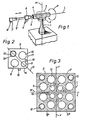
- this is attached to a column 1 rotatable about a vertical central axis M, which carries at its upper end a block 2 on which a cylindrical part 3 is arranged horizontally.
- a guide or frame piece 4 can be rotated about a longitudinal axis L (cf. double arrow P in FIG. 1), which can thus perform a pivoting movement about the axis M and a rotary movement about the axis L.
- the support arm 5 can be telescopically extended and retracted into and out of the guide or frame piece 4 and can therefore also assume the position 5 '.
- the support arm carries z. B. a gripper device or, as in the example shown, a spray head 6, which is provided with corresponding spray nozzles 7.
- the spray nozzles 7 can also be brought into the position 7 'as they can be pivoted in a circular arc about the axis M and rotated about the longitudinal axis L.
- the support arm 5 is formed in the embodiment according to FIGS. 2 to 4 from four individual elements 8 which, as can be seen from FIG. 3, can be assembled to form a square structure in cross section of the support arm.
- the two individual elements 8 ', 8 "of FIG. 3 impart the same resistance moments as the individual elements 8'" and 8 "" with respect to the axis X, which is located in the longitudinal center plane M of the support arm. This means that the support arm can be rotated through 180 ° and has the same resistance values, so that the tool at the free end of the support arm has the same position in space as when the support arm is rotated through 180 °.
- each individual element has larger bores 9, 10 and a smaller bore 11.
- the further bore 12 is provided near the end of the support arm with a thread 13 and serves to receive the threaded shaft of the screws with which the end cover or z. B. the machining tool 7 is screwed to the end of the support arm.
- the holes 9 to 12 are provided symmetrical to the diagonal D in the case shown. They lie cross-symmetrically in the arm with respect to the center F of the support arm 5, the larger bores 9, 10 forming a circle around the central longitudinal axis F of the arm, while the smaller bores 11 likewise form a circle with four or in a square arrangement are located about the longitudinal central axis F. The same symmetrical arrangement can also be seen in the holes 12.
- Such a single element as element 8 can be easily produced by extrusion in aluminum or an aluminum alloy.
- the holes 9 to 11 show a perfect smooth wall for guiding pneumatic and hydraulic media without the walls of the holes having defects that disrupt the flow of the media within the holes and so z. B. give rise to vibrations and noises of the support arm.
- the individual elements 8 'to 8 "" can be connected to one another with the aid of connecting parts.
- one side 14 of the individual element can have a spring-like longitudinal rib 15, and a corresponding recess 16 is provided on the second longitudinal side 17 of the individual element, so that the four elements according to FIG. 2 are connected to one another in the manner shown in FIG. 3. Any other connection of the individual elements by welding, pinning, riveting or the like is possible.
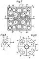
- Each wing 7 uses a cross-shaped middle piece 18 with the wings 19, 20, 21, 22, which are arranged identically and symmetrically about the central axis K of the middle piece 18.
- Each wing has a bore 23 which is also arranged symmetrically to the longitudinal and transverse median planes S and T of the cruciform center piece 18.
- Each wing 19 to 22 is separated or connected to its neighboring wing by an arcuate wall 24, the ends 24a, 24b of which are located at a distance b from one another.
- the cruciform center piece can also have a central bore 25.
- Each of these individual elements in turn has the two bores 27, 28 symmetrically with respect to its diagonal D and also a bore 29 which is provided just as symmetrically with respect to the diagonal D as the threaded bore 30 which corresponds to the bore 12 of the exemplary embodiment according to FIG. 2.
- the bore 29 forms a central eye in an extension 31 of the individual element 26, the outer wall 31 a of the round extension corresponding in diameter and configuration of the wall 24 of the crosspiece 18.
- the connecting web 32 between the central region of the individual element 26 and the extension 31, which is also symmetrical to the diagonal D, has a width e which corresponds to the distance b between the ends 24a and 24b of the wall 24.
- the individual elements 26 can be inserted in the longitudinal direction of the cruciform center piece 18 and connected to one another by pinning, welding or the like.
- the end cover or the end head plate of the processing element 7 can also ensure that the individual elements are held together, provided the length of the support arm permits this.
- the cohesion of the individual elements has no influence on the tightness of the bores, which show a closed cross section over the length of the individual elements.
- the support arm 5 has a circular shape and consists of a center piece 41, which can be a tube, and four identical individual elements 42, the bores 43, 44 of which are in turn arranged symmetrically in the direction of the diagonal D and are cross-shaped with respect to the arm 40 to the center point U of the arm.
- the resistance moments of the embodiments according to FIGS. 2 to 7 also apply to this configuration of the support arm.
Landscapes
- Engineering & Computer Science (AREA)
- Mechanical Engineering (AREA)
- Robotics (AREA)
- Manipulator (AREA)
- Load-Engaging Elements For Cranes (AREA)
Priority Applications (1)
| Application Number | Priority Date | Filing Date | Title |
|---|---|---|---|
| AT87115461T ATE53784T1 (de) | 1986-10-25 | 1987-10-22 | Pneumatische oder hydraulische medien oder leitungen fuehrender tragarm. |
Applications Claiming Priority (2)
| Application Number | Priority Date | Filing Date | Title |
|---|---|---|---|
| DE19863636462 DE3636462A1 (de) | 1986-10-25 | 1986-10-25 | Pneumatische oder hydraulische medien oder leitungen fuehrender tragarm |
| DE3636462 | 1986-10-25 |
Publications (2)
| Publication Number | Publication Date |
|---|---|
| EP0265835A1 EP0265835A1 (de) | 1988-05-04 |
| EP0265835B1 true EP0265835B1 (de) | 1990-05-02 |
Family
ID=6312531
Family Applications (1)
| Application Number | Title | Priority Date | Filing Date |
|---|---|---|---|
| EP87115461A Expired - Lifetime EP0265835B1 (de) | 1986-10-25 | 1987-10-22 | Pneumatische oder hydraulische Medien oder Leitungen führender Tragarm |
Country Status (3)
| Country | Link |
|---|---|
| EP (1) | EP0265835B1 (enExample) |
| AT (1) | ATE53784T1 (enExample) |
| DE (1) | DE3636462A1 (enExample) |
Families Citing this family (11)
| Publication number | Priority date | Publication date | Assignee | Title |
|---|---|---|---|---|
| SE462705B (sv) * | 1987-11-23 | 1990-08-20 | Maans Gunnar Thuresson Mannerf | Arm avsedd foer materialhantering- eller bearbetningsanordning |
| JP2846346B2 (ja) * | 1989-06-23 | 1999-01-13 | 株式会社ブリヂストン | 湾曲可能なアクチュエータ |
| FR2661630B1 (fr) * | 1990-05-04 | 1992-08-07 | Renault | Dispositif permettant le maintien et/ou l'assemblage automatique de pieces, comportant des bras porte-outils montes sur un bloc-support. |
| FR2664676B1 (fr) * | 1990-07-10 | 1992-11-27 | Sacatec | Profile, notamment pour bras de service, en particulier pour bras de poncage, et bras de service correspondant. |
| US5540541A (en) * | 1990-11-28 | 1996-07-30 | Robert Bosch Gmbh | Pivotal robot arm |
| DE4037773A1 (de) * | 1990-11-28 | 1992-06-04 | Bosch Gmbh Robert | Schwenkarmroboter |
| FR2682909B1 (fr) * | 1991-10-25 | 1994-01-28 | Arilon | Robot industriel a cadence elevee pour le deplacement d'un outil suivant les trois axes d'un repere cartesien orthogonal. |
| DE19635832C2 (de) * | 1996-09-04 | 2000-12-07 | Freudenberg Carl Fa | Tragarm und Verfahren zu seiner Herstellung |
| DE102005014863A1 (de) * | 2005-03-30 | 2006-10-05 | Focke & Co.(Gmbh & Co. Kg) | Vorrichtung zum Aufnehmen und Fördern von Gegenständen |
| EP2762266A4 (en) * | 2011-09-22 | 2015-06-03 | Gmtk Multi Process Machining S A | ARM AND MULTICOPPLER FOR AUTOMATIC CONNECTION WITH MACHINING ACCESSORIES IN TOOLING MACHINES |
| JP5698783B2 (ja) * | 2013-03-29 | 2015-04-08 | ファナック株式会社 | 分線盤を備えたロボット |
Family Cites Families (5)
| Publication number | Priority date | Publication date | Assignee | Title |
|---|---|---|---|---|
| SE339807B (enExample) * | 1970-02-23 | 1971-10-18 | Kaufeldt Ingenjors Ab R | |
| EP0000877B1 (de) * | 1977-08-31 | 1983-05-18 | Grisebach, Hans-Theodor | Manipulator zum Positionieren von Werkstücken oder anderen Lasten |
| SE439968B (sv) * | 1982-10-19 | 1985-07-08 | Ulf Kenneth Folke Fasth | Stelldon |
| FR2540849B1 (fr) * | 1983-02-15 | 1986-11-07 | Lach Pierre | Verin electrique |
| DE3417121A1 (de) * | 1984-05-09 | 1985-11-14 | Max Kettner Verpackungsmaschinenfabrik GmbH & Co KG, 8000 München | Handhabungsgeraet |
-
1986
- 1986-10-25 DE DE19863636462 patent/DE3636462A1/de active Granted
-
1987
- 1987-10-22 EP EP87115461A patent/EP0265835B1/de not_active Expired - Lifetime
- 1987-10-22 AT AT87115461T patent/ATE53784T1/de active
Also Published As
| Publication number | Publication date |
|---|---|
| DE3636462A1 (de) | 1988-05-11 |
| DE3636462C2 (enExample) | 1991-09-19 |
| ATE53784T1 (de) | 1990-06-15 |
| EP0265835A1 (de) | 1988-05-04 |
Similar Documents
| Publication | Publication Date | Title |
|---|---|---|
| DE102016218298B4 (de) | Greifvorrichtung | |
| EP0265835B1 (de) | Pneumatische oder hydraulische Medien oder Leitungen führender Tragarm | |
| DE69102841T2 (de) | Industrieroboter mit leitungsmechanismus. | |
| DE1810552B2 (de) | Drehgelenk mit horizontaler Schwenkachse für über Federausgleich verbundene Schwenkarme, insbesondere von medizinischen Geräten | |
| DE10158724B4 (de) | Öffnungs- und Schließspannfutter | |
| AT393303B (de) | Vorrichtung zum verbinden von bauteilen | |
| EP0196523B1 (de) | Radialpresse | |
| DE3108290C2 (de) | Bohrlehre | |
| DE3142572C2 (de) | Vorrichtung zum lösbaren Verbinden von Seilenden, insbesondere von Seilen bei umlaufenden Seiltrieben, Seilförderern oder Aufhängungen | |
| EP0512083B1 (de) | Schwenkarmroboter | |
| DE3627918A1 (de) | Zentrisch greifender dreifingergreifer | |
| DE3503401A1 (de) | Fuehrungsvorrichtung fuer einen laserstrahl, vorzugsweise zur dreidimensionalen werkstueckbearbeitung | |
| EP2371482A1 (de) | Werkzeugmaschine | |
| DE102014103199B3 (de) | Roboterarm mit einer Verstellstruktur | |
| EP0303905B1 (de) | Flanschverbindung | |
| DE620052C (de) | Vorrichtung zum Ausschleifen schraubengangfoermiger, vorgearbeiteter Nuten und aehnlicher Vertiefungen im Innern von Rohren | |
| DE2313125A1 (de) | Vorrichtung zum abisolieren von draehten od.dgl | |
| DE2045295C3 (de) | Verschraubungselement mit zwei koaxialen Gewindestücken | |
| DE2308654C3 (de) | Bohrkopf | |
| DE10203791B4 (de) | Fluidische Arbeitseinheit mit integrierter Ansteuerelektronik | |
| DE1798419C (de) | Aufnahmekopf fur Meß- und Anreiß werk zeuge Ausscheidung aus 1773282 | |
| EP0802016A1 (de) | Werkzeugmaschine mit einem Drehtisch | |
| DE2255647C3 (de) | Indexierung für einen längsverschiebbaren Revolverkopf einer Drehmaschine | |
| DE922281C (de) | Richteinrichtung fuer Draht- oder Stabrichtgeraete oder -maschinen | |
| DE1810552C (de) | Drehgelenk mit horizontaler Schwenk achse fur über Federausgleich verbundene Schwenkarme, insbesondere von medizini sehen Geraten |
Legal Events
| Date | Code | Title | Description |
|---|---|---|---|
| PUAI | Public reference made under article 153(3) epc to a published international application that has entered the european phase |
Free format text: ORIGINAL CODE: 0009012 |
|
| AK | Designated contracting states |
Kind code of ref document: A1 Designated state(s): AT BE CH ES FR GB IT LI NL SE |
|
| 17P | Request for examination filed |
Effective date: 19880530 |
|
| 17Q | First examination report despatched |
Effective date: 19890925 |
|
| GRAA | (expected) grant |
Free format text: ORIGINAL CODE: 0009210 |
|
| AK | Designated contracting states |
Kind code of ref document: B1 Designated state(s): AT BE CH ES FR GB IT LI NL SE |
|
| PG25 | Lapsed in a contracting state [announced via postgrant information from national office to epo] |
Ref country code: IT Free format text: LAPSE BECAUSE OF FAILURE TO SUBMIT A TRANSLATION OF THE DESCRIPTION OR TO PAY THE FEE WITHIN THE PRESCRIBED TIME-LIMIT;WARNING: LAPSES OF ITALIAN PATENTS WITH EFFECTIVE DATE BEFORE 2007 MAY HAVE OCCURRED AT ANY TIME BEFORE 2007. THE CORRECT EFFECTIVE DATE MAY BE DIFFERENT FROM THE ONE RECORDED. Effective date: 19900502 Ref country code: FR Effective date: 19900502 Ref country code: NL Effective date: 19900502 Ref country code: SE Effective date: 19900502 |
|
| REF | Corresponds to: |
Ref document number: 53784 Country of ref document: AT Date of ref document: 19900615 Kind code of ref document: T |
|
| GBT | Gb: translation of ep patent filed (gb section 77(6)(a)/1977) | ||
| PG25 | Lapsed in a contracting state [announced via postgrant information from national office to epo] |
Ref country code: ES Free format text: LAPSE BECAUSE OF FAILURE TO SUBMIT A TRANSLATION OF THE DESCRIPTION OR TO PAY THE FEE WITHIN THE PRESCRIBED TIME-LIMIT Effective date: 19900813 |
|
| EN | Fr: translation not filed | ||
| NLV1 | Nl: lapsed or annulled due to failure to fulfill the requirements of art. 29p and 29m of the patents act | ||
| PG25 | Lapsed in a contracting state [announced via postgrant information from national office to epo] |
Ref country code: AT Effective date: 19901022 |
|
| PG25 | Lapsed in a contracting state [announced via postgrant information from national office to epo] |
Ref country code: CH Effective date: 19901031 Ref country code: BE Effective date: 19901031 Ref country code: LI Effective date: 19901031 |
|
| PLBE | No opposition filed within time limit |
Free format text: ORIGINAL CODE: 0009261 |
|
| STAA | Information on the status of an ep patent application or granted ep patent |
Free format text: STATUS: NO OPPOSITION FILED WITHIN TIME LIMIT |
|
| 26N | No opposition filed | ||
| BERE | Be: lapsed |
Owner name: HONSEL-WERKE A.G. Effective date: 19901031 |
|
| REG | Reference to a national code |
Ref country code: CH Ref legal event code: PL |
|
| PG25 | Lapsed in a contracting state [announced via postgrant information from national office to epo] |
Ref country code: GB Effective date: 19911022 |
|
| GBPC | Gb: european patent ceased through non-payment of renewal fee |