EP0264310A2 - Kessel für Warmwasserbereitung - Google Patents
Kessel für Warmwasserbereitung Download PDFInfo
- Publication number
- EP0264310A2 EP0264310A2 EP87402031A EP87402031A EP0264310A2 EP 0264310 A2 EP0264310 A2 EP 0264310A2 EP 87402031 A EP87402031 A EP 87402031A EP 87402031 A EP87402031 A EP 87402031A EP 0264310 A2 EP0264310 A2 EP 0264310A2
- Authority
- EP
- European Patent Office
- Prior art keywords
- tank
- water
- hot water
- boiler
- boiler according
- Prior art date
- Legal status (The legal status is an assumption and is not a legal conclusion. Google has not performed a legal analysis and makes no representation as to the accuracy of the status listed.)
- Withdrawn
Links
Images


Classifications
-
- F—MECHANICAL ENGINEERING; LIGHTING; HEATING; WEAPONS; BLASTING
- F24—HEATING; RANGES; VENTILATING
- F24H—FLUID HEATERS, e.g. WATER OR AIR HEATERS, HAVING HEAT-GENERATING MEANS, e.g. HEAT PUMPS, IN GENERAL
- F24H1/00—Water heaters, e.g. boilers, continuous-flow heaters or water-storage heaters
- F24H1/18—Water-storage heaters
- F24H1/20—Water-storage heaters with immersed heating elements, e.g. electric elements or furnace tubes
- F24H1/201—Water-storage heaters with immersed heating elements, e.g. electric elements or furnace tubes using electric energy supply
- F24H1/202—Water-storage heaters with immersed heating elements, e.g. electric elements or furnace tubes using electric energy supply with resistances
-
- F—MECHANICAL ENGINEERING; LIGHTING; HEATING; WEAPONS; BLASTING
- F24—HEATING; RANGES; VENTILATING
- F24H—FLUID HEATERS, e.g. WATER OR AIR HEATERS, HAVING HEAT-GENERATING MEANS, e.g. HEAT PUMPS, IN GENERAL
- F24H9/00—Details
- F24H9/0005—Details for water heaters
- F24H9/001—Guiding means
- F24H9/0015—Guiding means in water channels
- F24H9/0021—Sleeves surrounding heating elements or heating pipes, e.g. pipes filled with heat transfer fluid, for guiding heated liquid
-
- F—MECHANICAL ENGINEERING; LIGHTING; HEATING; WEAPONS; BLASTING
- F24—HEATING; RANGES; VENTILATING
- F24H—FLUID HEATERS, e.g. WATER OR AIR HEATERS, HAVING HEAT-GENERATING MEANS, e.g. HEAT PUMPS, IN GENERAL
- F24H9/00—Details
- F24H9/12—Arrangements for connecting heaters to circulation pipes
- F24H9/13—Arrangements for connecting heaters to circulation pipes for water heaters
- F24H9/133—Storage heaters
Definitions
- the invention relates to a boiler for the production of hot water.
- the boiler consists of a tank for heating water, a means of heating this tank, a hot water outlet pipe leaving from the upper part of the tank, and a return pipe opening into the lower part of this tank.
- This boiler is characterized in that it is provided with a control valve connected to a control circuit comprising a means for measuring the outside temperature and a temperature probe connected to the return line, this valve being connected to the lines of water outlet and return so as to introduce water, coming from the return pipe, into the hot water outlet pipe, according to the temperature of the return water and taking into account the outside temperature.
- the boiler constitutes an electric boiler and the tank is housed, with the interposition of a thermally insulating material inside a buried enclosure provided with a cover into which an airlock communicates with an orifice provided at the upper end of the tank, this orifice being provided with an integral closure member of the electrical heating resistance immersed in the tank.
- a cylindrical body is fixed under the shutter member, this cylindrical body opening at its ends close to the lower and upper ends of the tank, the electrical heating resistance being arranged at the inside this cylindrical body, while on the outer wall is fixed a device for compensating for the expansion of the water, the dimensions of this device being smaller than those of the opening of the tank and the airlock.
- the object of the invention is therefore to produce an electric boiler for the production of hot heating water and, optionally, domestic hot water, which allows a reduction in the consumption of electric energy and a reduction in the cost. of this energy insofar as this boiler is designed so that, during the night, that is to say during the off-peak hours when the electrical energy is less expensive, it not only ensures the distribution of hot water for heating , but also ensures the accumulation of hot water which is then distributed during the day, that is to say at times when electrical energy is more expensive.
- This boiler is also designed so that, during operation, the temperature of the hot water dispensed is just sufficient to bring the temperature of the premises to be heated to the desired value, taking account of the outside temperature and to achieve this result, according to the invention, to carry out a regulation on the return water circuit, by adjusting the temperature of this return water as a function of the outside temperature, according to a law established in advance by the electronic part of a regulation circuit, this adjustment of the return temperature being effected by bringing, at each instant, a variable quantity of this return water into the hot water flow pipe from the boiler.
- the present invention also aims to achieve a boiler which is perfectly thermally insulated, which is not likely to clutter the interior of the premises to be heated to the extent that this boiler is buried, this boiler allowing however easy access to the various organs that constitute it.
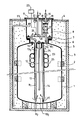
- This boiler consists of a tank 1 which is positioned, for example, by wooden wedges 2, inside a concrete enclosure 3, preferably prefabricated, embedded in the ground and closed by a cover 4.
- a thermally insulating material 5 is placed between the tank 1 and the enclosure 3, this material being for example constituted by vermiculite.
- This arrangement makes it possible to obtain good thermal insulation of the tank of the boiler while avoiding the drawbacks linked to its bulk.
- the tank 1 which is of generally cylindrical shape, with a vertical axis, has at its upper end an opening, provided with a flange 6, which is closed by a shutter member 7.
- the space of the enclosure 3, located between the flange 6 and the cover 4, is occupied by an airlock 8 whose dimensions are such that it allows the passage of the shutter member 7.
- This airlock 8 which opens out through the cover 4, is itself closed by a closure plate 9 which is crossed, on the one hand by the pipe 10 for hot water outlet, which supplies hot water to the premises to be heated, on the other hand by the return pipe 11 which brings the cooled water back inside the tank 1.
- the hot water outlet pipe 10 opens at 101 under the cover 7 at the upper end of the tank, while the return pipe 11 extends at 111 inside the tank to open at 112 at its end lower.
- the electrical heating resistor 12 is fixed under the shutter member 7 of the tank and is placed inside a cylindrical body 13 also fixed to the shutter member 7 by tie rods 131.
- This cylindrical body 13 is of a length such that it opens at its upper and lower ends near the upper and lower ends of the tank, in order to create a circulation of water. Indeed, during operation, the cold water enters the cylindrical body 13 through its lower orifice 132, it rises inside this cylindrical body during its heating by the resistor 12 and it exits through the orifice higher 133 after heating.
- a nozzle 24 is provided around the upper end 133 of the body 13 so as to allow the adjustment of the hot water passage section so that it reaches in a determined time the temperature of accumulation of hot water and, for example, 105 °. This nozzle will preferably be adjusted once and for all during the construction of the boiler according to the power electric heating resistance.
- the cylindrical body 13 inside which the resistor 12 is disposed also contains the return pipe 11 as well as a tube 14 whose lower end, disposed near the base of the tank, is provided with a probe.
- temperature 15 intended to cut off the supply of the heating resistor 12 when the temperature of the water at the base of the tank reaches a determined temperature and, for example, 100 °.
- the heating resistor 12 is also under the control of a probe 16 placed under the shutter member 7, that is to say in the upper part of the tank, in order to cut sequentially, via '' a circuit breaker, supplying the electrical resistance 12.
- the hot water outlet pipe 10 is provided with a circulation pump 17, a discharge valve 18 and a temperature limiter 19.
- the return pipe 11, which extends at 111 inside the tank is provided, inside the airlock 8, with a control valve 20 which is connected, by a bypass outlet 21, to the pipe water outlet 10 upstream of pump 17.
- This regulation valve 20 is controlled by a regulation circuit which includes the temperature probe 22 connected to the return circuit 11 and the temperature probe 221 which measures the outside temperature.
- This valve 20 and its regulation circuit are designed to introduce water, coming from the return pipe 11, into the hot water outlet pipe 10, as a function of the temperature of this return water (probe 22 ) and taking into account the ambient temperature (probe 22 sonde), so as to adapt the hot water flow temperature so that the return water temperature is of a determined value taking into account the ambient temperature.
- This arrangement makes it possible to reduce the consumption of the accumulated heat energy.
- a pipe 23 which also ends, outside the tank 1, at the base of the enclosure 3.
- This pipe 23 is intended to be connected to a lifting pump to allow the evacuation of water which could accumulate at the base of the enclosure.
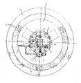
- a device which consists of several flexible toric enclosures 24, inflated by air and which are held around the cylindrical body 13 by legs perforated 25.
- the dimensions of the assembly provided with these perforated tabs 25 fixed to the cylindrical body 13, are smaller than the dimensions of the upper opening of the tank 1, so that, by removing the cover 7, the resistor 12 is simultaneously removed, the pipe 111, the tubing 14 and the device 24, 25 for compensating for the expansion of the water.
- This arrangement facilitates the construction, assembly and possible repairs of the boiler.
- the water is heated by an electrical resistor 12 in contact with which passes the water to be heated before being discharged through line 10.
- the pipe 111 of the tank, as well as the resistor 12, are arranged inside a cylindrical body 13 ensuring a circulation of water from the outside of this cylindrical body and towards the inside via the end lower.
- the upper opening of the tank delimited by the flange 6 is provided with a cylindrical sleeve 28 which is sealed in the upper part of the tank at the periphery of its opening, this sleeve immersing in the water of the tank.
- This sleeve 28 delimits externally, in the upper part of the tank, a volume 29 filled with a neutral gas, while, on the surface of the tank water, floats a layer 30 of a liquid product immiscible with l water, such as oil or paraffin.
- This volume of gas is intended to compensate for the expansion of the water in the tank.
- the inner end of the water return pipe 11 has at its lower end a flat enclosure 31, the periphery 32 of the lower face 33 is provided with an opening whose cross section is large.
- the purpose of this opening is to distribute the water, which returns to the tank through line 1, at low speed at the base of this tank, so as not to create vortices and so that the gravitational movement of the water is not disturbed by the arrival of cold water.
- this arrangement makes it possible to maintain the stratification of the water as a function of its temperature.
- the enclosure 31 may also include, if this is deemed necessary, perforations through its lower face 33, the main thing being that the total area of the orifices 32 and 33 is large, in order to reduce the flow rate of the cooled water.
- the section of the enclosure 31 corresponds to that of the cylindrical body and is less than that of the sleeve 28.
- the boiler according to the invention will, moreover, be provided with a regulating device (not shown) and constituted by an electronic cabinet connected so as to control the switching on and off of the boiler, in order to cause or not the supply of the heating resistor 12.
- This regulating device will be designed so as to be able to be controlled by a coded signal of electromagnetic waves and allow the boiler to be started at off-peak hours of electrical energy consumption.
- a temperature probe 34 immersed in the water of the tank, is connected to this circuit.
Landscapes
- Engineering & Computer Science (AREA)
- Physics & Mathematics (AREA)
- Thermal Sciences (AREA)
- Chemical & Material Sciences (AREA)
- Combustion & Propulsion (AREA)
- Mechanical Engineering (AREA)
- General Engineering & Computer Science (AREA)
- Heat-Pump Type And Storage Water Heaters (AREA)
- Domestic Hot-Water Supply Systems And Details Of Heating Systems (AREA)
Applications Claiming Priority (4)
| Application Number | Priority Date | Filing Date | Title |
|---|---|---|---|
| FR8612772 | 1986-09-12 | ||
| FR8612772A FR2603977B1 (fr) | 1986-09-12 | 1986-09-12 | Chaudiere pour la production d'eau chaude |
| FR878712615A FR2620524B2 (fr) | 1986-09-12 | 1987-09-11 | Chaudiere pour la production d'eau chaude |
| FR8712615 | 1987-09-11 |
Publications (2)
| Publication Number | Publication Date |
|---|---|
| EP0264310A2 true EP0264310A2 (de) | 1988-04-20 |
| EP0264310A3 EP0264310A3 (de) | 1988-06-22 |
Family
ID=26225473
Family Applications (1)
| Application Number | Title | Priority Date | Filing Date |
|---|---|---|---|
| EP87402031A Withdrawn EP0264310A3 (de) | 1986-09-12 | 1987-09-11 | Kessel für Warmwasserbereitung |
Country Status (2)
| Country | Link |
|---|---|
| EP (1) | EP0264310A3 (de) |
| FR (1) | FR2620524B2 (de) |
Cited By (4)
| Publication number | Priority date | Publication date | Assignee | Title |
|---|---|---|---|---|
| FR2689217A1 (fr) * | 1992-03-31 | 1993-10-01 | Chaffoteaux Et Maury | Perfectionnements aux chauffe-eau électriques comprenant un ballon cylindrique de grande capacité. |
| ES2083313A2 (es) * | 1991-10-04 | 1996-04-01 | Tenreiro Luis Regueiro | Dispositivo de calentamiento en un fluido para su utilizacion en calefacciones y similares. |
| ES2120323A1 (es) * | 1995-02-28 | 1998-10-16 | Univ Pais Vasco | Acumulador de agua caliente con estratificacion artificial. |
| CN106225220A (zh) * | 2016-07-19 | 2016-12-14 | 宁波帅康热水器有限公司 | 一种高防水保温阻燃电热水器 |
Family Cites Families (8)
| Publication number | Priority date | Publication date | Assignee | Title |
|---|---|---|---|---|
| DE471432C (de) * | 1929-02-12 | Voigt & Haeffner Akt Ges | Elektrisch beheizter Heisswasserbereiter | |
| GB989180A (en) * | 1960-05-04 | 1965-04-14 | Mads Clausen | Method of operating a hot-water space-heating system |
| DE1679764B2 (de) * | 1967-12-20 | 1976-01-29 | Elektrischer heisswasserspeicher | |
| DE1903774A1 (de) * | 1969-01-25 | 1970-08-13 | Erwin Egenberger | Vorrichtung zum Erhitzen fluessiger Medien |
| CH564173A5 (de) * | 1973-08-24 | 1975-07-15 | Luwa Ag | |
| DE2427641B2 (de) * | 1974-06-07 | 1977-09-22 | Satchwell-Birka Regelungstechnik Gmbh, 5650 Solingen | Einrichtung zur regelung der ruecklauftemperatur einer heizungsanlage |
| FR2518349A1 (fr) * | 1981-12-14 | 1983-06-17 | Petercem Sa | Circuit de raccordement d'un contacteur decaleur a un appareil electrique a accumulation d'energie, et procede de raccordement correspondant |
| DE3330478A1 (de) * | 1983-08-24 | 1985-03-07 | Peter Nied KG, 6340 Dillenburg | Heizanlage mit einem elektrisch beheizbaren waermespeicher |
-
1987
- 1987-09-11 EP EP87402031A patent/EP0264310A3/de not_active Withdrawn
- 1987-09-11 FR FR878712615A patent/FR2620524B2/fr not_active Expired - Lifetime
Cited By (5)
| Publication number | Priority date | Publication date | Assignee | Title |
|---|---|---|---|---|
| ES2083313A2 (es) * | 1991-10-04 | 1996-04-01 | Tenreiro Luis Regueiro | Dispositivo de calentamiento en un fluido para su utilizacion en calefacciones y similares. |
| FR2689217A1 (fr) * | 1992-03-31 | 1993-10-01 | Chaffoteaux Et Maury | Perfectionnements aux chauffe-eau électriques comprenant un ballon cylindrique de grande capacité. |
| ES2120323A1 (es) * | 1995-02-28 | 1998-10-16 | Univ Pais Vasco | Acumulador de agua caliente con estratificacion artificial. |
| CN106225220A (zh) * | 2016-07-19 | 2016-12-14 | 宁波帅康热水器有限公司 | 一种高防水保温阻燃电热水器 |
| CN106225220B (zh) * | 2016-07-19 | 2019-02-05 | 宁波帅康热水器有限公司 | 一种高防水保温阻燃电热水器 |
Also Published As
| Publication number | Publication date |
|---|---|
| FR2620524B2 (fr) | 1990-03-30 |
| FR2620524A2 (fr) | 1989-03-17 |
| EP0264310A3 (de) | 1988-06-22 |
Similar Documents
| Publication | Publication Date | Title |
|---|---|---|
| EP0116005A1 (de) | Vorrichtung für Frostschutz von Wasserzählern und Wasserhähnen | |
| CH551126A (fr) | Chaudiere a electrodes pour le chauffage d'un piquide conducteur. | |
| EP0493210B1 (de) | Solar-Wärmespeicher und Anlage zur Kühlung und Klimatisierung oder Seewasserentsalzung | |
| EP0264310A2 (de) | Kessel für Warmwasserbereitung | |
| CA1217708A (fr) | Dispositif de distribution de liquide cryogenique | |
| EP0418179B1 (de) | Elektrischer Kessel mit hydraulischer Turbulenz | |
| FR2562767A1 (fr) | Appareil pour la cuisson d'aliments | |
| EP0317444B1 (de) | Dampferzeuger | |
| EP0323942B1 (de) | Heisswasserspeicher und Verfahren zum Heizen dieses Speichers | |
| FR2713405A1 (fr) | Module d'amenée de courant pour l'alimentation d'une charge électrique supraconductrice à basse température critique. | |
| EP4065901A1 (de) | Vorrichtung zum produzieren von heisser flüssigkeit | |
| FR2583141A1 (fr) | Generateur de vapeur a resistance electrique pour appareil electromenager | |
| EP0085590A1 (de) | Fluidansaugvorrichtung, angeordnet in einem Tank, speziell für flüssige Brennstoffe | |
| FR2553181A1 (fr) | Dispositif permettant le stockage thermique a partir de deux sources energetiques, et installation utilisant un tel dispositif | |
| FR2595137A1 (fr) | Chauffe-eau electriques munis d'un systeme d'obtention rapide d'eau chaude | |
| WO2007080261A1 (fr) | Dispositif de chauffage d’eau pour un appareil electromenager | |
| EP2045543B1 (de) | Heizkessel mit Rauchrohren | |
| EP0224537B1 (de) | Kühltunnel | |
| FR2770306A1 (fr) | Pluviometre pour toutes conditions de precipitations | |
| FR2578878A1 (fr) | Dispositif chauffable de distribution d'eau pour etables non couvertes | |
| FR2506908A1 (fr) | Chaudiere electrique | |
| FR2568990A1 (fr) | Perfectionnement aux appareils solaires pour echauffement de liquides | |
| BE572694A (de) | ||
| FR2752456A1 (fr) | Dispositif pour le transfert regule de frigories entre une reserve et une enceinte de conservation | |
| FR2717517A1 (fr) | Borne de puisage pourvue d'un dispositif automatique de protection anti-gel. |
Legal Events
| Date | Code | Title | Description |
|---|---|---|---|
| PUAI | Public reference made under article 153(3) epc to a published international application that has entered the european phase |
Free format text: ORIGINAL CODE: 0009012 |
|
| AK | Designated contracting states |
Kind code of ref document: A2 Designated state(s): AT BE CH DE ES GB GR IT LI LU NL SE |
|
| PUAL | Search report despatched |
Free format text: ORIGINAL CODE: 0009013 |
|
| AK | Designated contracting states |
Kind code of ref document: A3 Designated state(s): AT BE CH DE ES GB GR IT LI LU NL SE |
|
| 17P | Request for examination filed |
Effective date: 19880729 |
|
| 17Q | First examination report despatched |
Effective date: 19900504 |
|
| STAA | Information on the status of an ep patent application or granted ep patent |
Free format text: STATUS: THE APPLICATION IS DEEMED TO BE WITHDRAWN |
|
| 18D | Application deemed to be withdrawn |
Effective date: 19910327 |
|
| RIN1 | Information on inventor provided before grant (corrected) |
Inventor name: DWORAK, GEORGES Inventor name: DWORAK, BERTRAND |