EP0261307A2 - Boîtier modulaire protégé des explosions - Google Patents
Boîtier modulaire protégé des explosions Download PDFInfo
- Publication number
- EP0261307A2 EP0261307A2 EP87106856A EP87106856A EP0261307A2 EP 0261307 A2 EP0261307 A2 EP 0261307A2 EP 87106856 A EP87106856 A EP 87106856A EP 87106856 A EP87106856 A EP 87106856A EP 0261307 A2 EP0261307 A2 EP 0261307A2
- Authority
- EP
- European Patent Office
- Prior art keywords
- module housing
- plug
- housing according
- bore
- pin
- Prior art date
- Legal status (The legal status is an assumption and is not a legal conclusion. Google has not performed a legal analysis and makes no representation as to the accuracy of the status listed.)
- Granted
Links
Images


Classifications
-
- H—ELECTRICITY
- H05—ELECTRIC TECHNIQUES NOT OTHERWISE PROVIDED FOR
- H05K—PRINTED CIRCUITS; CASINGS OR CONSTRUCTIONAL DETAILS OF ELECTRIC APPARATUS; MANUFACTURE OF ASSEMBLAGES OF ELECTRICAL COMPONENTS
- H05K7/00—Constructional details common to different types of electric apparatus
- H05K7/14—Mounting supporting structure in casing or on frame or rack
- H05K7/1438—Back panels or connecting means therefor; Terminals; Coding means to avoid wrong insertion
- H05K7/1452—Mounting of connectors; Switching; Reinforcing of back panels
- H05K7/1454—Alignment mechanisms; Drawout cases
-
- H—ELECTRICITY
- H05—ELECTRIC TECHNIQUES NOT OTHERWISE PROVIDED FOR
- H05K—PRINTED CIRCUITS; CASINGS OR CONSTRUCTIONAL DETAILS OF ELECTRIC APPARATUS; MANUFACTURE OF ASSEMBLAGES OF ELECTRICAL COMPONENTS
- H05K7/00—Constructional details common to different types of electric apparatus
- H05K7/14—Mounting supporting structure in casing or on frame or rack
- H05K7/1461—Slidable card holders; Card stiffeners; Control or display means therefor
-
- H—ELECTRICITY
- H05—ELECTRIC TECHNIQUES NOT OTHERWISE PROVIDED FOR
- H05K—PRINTED CIRCUITS; CASINGS OR CONSTRUCTIONAL DETAILS OF ELECTRIC APPARATUS; MANUFACTURE OF ASSEMBLAGES OF ELECTRICAL COMPONENTS
- H05K3/00—Apparatus or processes for manufacturing printed circuits
- H05K3/22—Secondary treatment of printed circuits
- H05K3/28—Applying non-metallic protective coatings
- H05K3/284—Applying non-metallic protective coatings for encapsulating mounted components
Definitions
- the invention relates to an explosion-proof module housing for electrical and / or electronic assemblies with the features of the preamble of claim 1.
- Explosion-proof housings for electronic assemblies are known from the Siemens catalog MP 29, part 10, June 1984, page 10/14, which contain a sand-filled chamber in which the circuit board with the electronic components is housed.
- the housing In order to make the electrical connections with the sand-encapsulated printed circuit board, the housing also contains a connection space which is of the "increased safety" type of protection and contains, for example, screw terminals for the connection wiring.
- Firmly connected cables lead from these screw terminals into the sand-filled chamber, where they are connected to the printed circuit board.
- the cable duct to the sand-filled chamber only needs to be designed according to IP 54.
- This structure is quite simple in itself and has the particular advantage that, because of the sand encapsulation, the housing only has to have small wall thicknesses, which are considerably smaller than in the case of housings which have the same volume in the protection class "pressure resistant" Encapsulation ".
- the sand filling improves the heat dissipation from the interior of the housing compared to the air filling in a flameproof housing. The electronic components can therefore be operated with higher power dissipation in this housing.
- the system or the corresponding part is therefore shut down for a relatively long period of time during troubleshooting or fault elimination, since the power supply is also switched off for the other module housings which are functioning properly. Not only must those parts of the system that are connected to the same power supply as the module to be replaced be shut down, but also those parts from which or to which signal lines lead that are no longer considered intrinsically safe in the sense of DIN EN 50020, although under Under certain circumstances, the system could continue to be operated at least to a limited extent even if the defective electronic assembly was removed.
- the electrical connections are made via a connector device that is designed to be explosion-proof, the connector device can be disconnected at any time without special electrical measures being otherwise required.
- the connection and disconnection of such a connector device is much faster than opening and restoring screwed electrical connections. Even if the system has to be shut down for any other reason to remove the module housing with the module to be replaced, the switch-off time is considerably shorter than with screwed connections.
- This pressure-resistant encapsulation can be achieved simply by the other part of the plug-in connection device containing a hole at the corresponding point, which together with the plug pin forms an ignition-proof gap, while the electrical contact point for the plug pin, based on the direction of insertion of the connector, behind the hole.
- the wall of the bore consists of electrical, non-conductive material. This contact point can be formed by a socket into which the plug pin finally penetrates.
- the plug pins for the formation of the ignition-proof gap have a relatively large length and, on the other hand, the sockets also take up space in the radial direction, it is expedient if the connector pin has an enlarged diameter in the region of the resulting ignition-proof gap, compared with that at its front End lying section that penetrates into the socket when inserted. In this way, the outer diameter of the socket can become almost equal to the outer diameter of the plug pin at the thickest point, while on the other hand a sufficient strength is obtained.
- switch means In order to meet the IP 54 protection requirement when the connector is disconnected, it is either possible to use switch means to de-energize the live sockets or plug pins, or to cover the sockets with automatically closing cover means.
- the covering means can be formed by one or more slides, which are mounted so as to be longitudinally displaceable transversely to the longitudinal axis of the bores for the bushings and contain openings corresponding to the pattern of the bores, so that the bores are closed in one slider position and the bores are released in the other slider position , wherein the actuation of the slider or slides takes place when the two parts of the connector device are plugged together.
- the pin closing the bore is not to be made of insulating material but of electrically conductive material, it is possible to place the bushing opposite the gap which is resistant to ignition set back limiting bore and to hold the slidable pin between the bore and the socket so that the pin makes electrical contact in one position with the socket, while in the other end position the electrical connection is interrupted while the pin is actuated done by the connector pin.
- a very simple locking possibility consists in attaching a membrane made of elastic material in front of the holes, which is slotted or cut in the area of the holes, such that the plug pins penetrate through the membrane into the holes or sockets when the parts of the plug connection device are plugged together can while the diaphragm returns to its original position when the connector pins are pulled to close the holes to IP 54.
- the new module housing is preferably used in a subrack that contains one or more pairs of guide members for the module housing in a frame, which receive the guide members when the module housing is inserted, the part of the module housing assigned to the module housing being inserted when the module housing is inserted Plug connection device comes to rest, the complementary part of the plug connection device is arranged.
- unprotected plug connection devices can also be held for this purpose, via which the intrinsically safe connections are made.
- the subrack together with the explosion-proof module housings, forms a module plug-in system into which largely any module housing can be inserted or from which this module housing can be removed without having to switch off voltages for reasons of explosion protection.
- the part of the plug connection device accommodated in the subrack either contains a connection space of increased security for the connection of the lines or the lines are cast in a known manner in this part of the plug connection device in an explosion-proof manner.
- the contact means of the plug-in connection device In addition to the pressure-resistant encapsulation of the contact means of the plug-in connection device, it is also possible to design the contact means in the type of protection "increased safety" according to DIN EN 50019 "e" in order to obtain an easily replaceable module housing.
- a switch in the "flameproof enclosure” type of protection is inevitably provided at least in that part of the connector device, the contact means of which would otherwise be under voltage after the two parts have been separated from one another. The switch disconnects the contact means.
- the spatial arrangement is such that the switches only close when the electrical connection is already established when the parts are put together between the contact means.
- the contact path formed by mutually assigned contact means of the two parts contains a multiplicity of contact points, each of which is largely resiliently movable. This ensures that in the current range in each case all contact points never lose the mechanical connection to the other contact means at the same time, which could result in sparks.
- the independently movable contact points can be provided either in the contact means designed as a socket or on the contact means designed as a plug.
- the attachment in the socket has the advantage of better protection for these resilient contact points, which are filigree in view of the necessary miniaturization and therefore require protection.
- Possible movable contact points are both lamellae which are formed on a correspondingly slotted sleeve and, for example, tuft plugs, as are otherwise e.g. find application in the high frequency range.
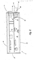
- FIG. 1 is a perspective and schematic or simplified illustration of an explosion-protected module plug-in system 1 which has a rack 2 and explosion-protected module housings 3 which can be pushed into the rack, only one of which is illustrated.
- the electrical connection between the subrack 2 and the module plug-in housing 3 takes place for the so-called "non-intrinsically safe" circuits via a two-part plug-in connection device 4 with a part 5 held in the subrack 2 and a part 6 attached to the module housing 3, both of which are plugged together for the contact materials in it form a pressure-resistant encapsulation according to DIN EN 50018.
- the intrinsically safe circuits are connected via a commercially available connector strip attached to the module housing 3, for example according to DIN 41612 or DIN 41617 or the like. is executed. When plugged in, this plug connector 7 makes contact in a socket connector fitted in the rack 2, which is also commercially available and is not shown for reasons of clarity.
- the subrack 2 contains a frame 8 with two side walls 9 and 11 which are connected to one another via a total of four support rails or struts 12, 13 and 14 which run parallel and at a distance from one another and are perpendicular to the side walls 9 and 11; the front lower mounting rail is not recognizable for reasons of illustration.
- the mounting rails 12 to 14 are screwed by means of screws 15 to the two side walls 9 and 11, namely the two mounting rails 12 and 13 on the top or top edge of the side walls 9 and 11, while the other two mounting rails, of which only the mounting rail 14 is visible, are arranged on the underside.
- the support rails 12, 13, 14 serve to hold guide rails 16 and 17 which, as the pair 16 and 17 show, contain guide grooves 18 and 19 which are open towards one another and aligned with one another.
- the guide rails 16 and 17 are screwed to the support rails 12, 13, 14 with screws 21, in such a way that they run parallel and at a distance from one another and parallel to the side walls 9, 11.
- 2 additional guide rails 16 ⁇ or 16 ⁇ are fastened in the frame 8 of the subrack with screws 21 ⁇ and 21 ⁇ .
- Corresponding guide rails attached to the underside are in alignment with these guide rails 16 ⁇ , 16 ⁇ , of which only the guide rail 17 ⁇ can be seen.
- the distance between the guide rails 16, 17 corresponds, as shown, to the height of the explosion-proof module housing 3, so that it can be inserted between the guide rails 16, 17 and held transversely to the insertion movement by the latter.
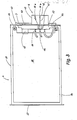
- the explosion-proof module housing 3 is illustrated open.
- This module housing with its two side walls 22, 23, a lower wall 24, an upper wall 25 and a rear wall 26 and a front wall 27 has approximately cuboids shaped shape and defines a chamber 28 in which electronic assemblies 29, which are built on printed circuit boards, are arranged.
- the chamber 28 of the explosion-proof module housing 3 is filled with sand or glass balls 30, so that there is a sand encapsulation for the modules 29 accommodated therein, ie the modules 29 are in the module housing 3 in the type of protection "sand encapsulation" according to DIN EN 50017 "q" protected.
- the walls 22 to 27 can be connected to one another in any way, provided that the connection technology selected in each case fulfills the corresponding protective regulations and the assemblies 29 in the chamber 28 are mechanically protected against dust and splash water in accordance with the protection regulation IP 54. If this protective regulation is observed, it is also ensured that the sand filling 30 remains in the chamber 28 and fulfills its protective function.
- the rear wall 26 of the module housing 3 shown contains two rectangular openings 33 and 34, in which the part 6 of the flameproof encapsulated connector device 4 and the connector strip 7 are inserted, the connector strip 7 also being designed and inserted in such a way that the module housing 3 fulfills the protection requirement IP 54 fulfilled; The same applies to part 6.
- the contact means of the connector strip 7 and the explosion-protected plug connection device 6 are connected to the electronic assemblies 29, either by soldering extensions 35 of the contact means directly into the circuit boards of the assemblies 29 or by means of a free wiring 36 leading from the contact means to the corresponding connection points on the printed circuit boards.
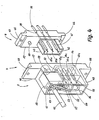
- both the part 6 seated in the module housing 3 and the part 5 of the explosion-protected plug-in connection device screwed into the subrack on the mounting rails 13 and 14 are shown in an enlarged perspective and the internal structure can be seen in this figure.
- part 6 contains an approximately plate-shaped base body 37 made of insulating material, which is produced, for example, in an injection molding process.
- a total of three essentially cylindrical plug pins 38a, 38b, 38c are anchored in the base body 37 in a pressure-tight manner, for example by being inserted into the base body 37 during their manufacture are injected.
- the connector pins consist, at least on their surface, of an electrically highly conductive material and protrude rearward through the base body 37, where they form connecting lugs 39 for the wiring 36. In order to immovably hold the connector pins 38a ...
- the part of the plug pins 38a... 38c projecting outwards with respect to the module housing 3 has two cylindrical sections 41 and 42 which are coaxial to one another but have different diameters, namely the longer section 41 with the larger diameter is the basic body 37 immediately adjacent, while the section 42 with the smaller diameter lies at the free tip of the connector pins 38a ... 38c.
- the group of a total of three connector pins 38a ... 38c is tubularly surrounded by a protective collar 43 which is designed in the manner of a short rectangular tube 43 and is an integral part of the base body 37.
- the protective collar 43 has a depth or length which corresponds to the length of the connector pins 38a ... 38c, ie the connector pins 38a ... 38c slightly tip back with respect to the front edge of the protective collar 43.
- Both the protective collar 43 and the plug pins 38a ... 38c run parallel to the guide strips 31, 32.
- the protective collar 43 does not need to be closed all round, but it can also contain slots if this is more favorable in terms of production technology.
- the part 6 is fastened in the module housing 3 with flanges 43 and 44, which are injection molded onto the base body 37 and, in the assembled state, bear against the rear or inside of the rear wall 26. Bores 45 for fastening screws are provided in the flanges.
- the part 5 of the plug connection device 4 attached to the holding rails 13 and 14 of the module carrier 2 has a housing-like insulating base body 46 with a base plate 47, on the back of which an extension 48 is integrally formed in the manner of a square tube piece.
- the base plate 47 contains cylindrical chambers or openings 49a ... 49c, the number and arrangement of which correspond to the number and the arrangement pattern of the plug pins 38a ... 38c or are mirror-symmetrical to these and extend into the extension 48 where they touch their back are sealed pressure-tight.
- 49c are identical to one another and consist of a first cylindrical section 51, which opens at the front of the part 5, and a second cylindrical section 52 behind it, in each of which an electrical socket 53 floats in the radial direction, but in the longitudinal direction is immovably housed.
- the diameter of the cylindrical section 51 corresponds to the diameter of the associated plug pin 38a ... 38c in the region 41 with the larger diameter, in such a way that when the plug pin 38a ... 38c is inserted into the corresponding chamber 49a ... 49c, between the cylindrical bore 51 and the section 41 there is an ignition-proof gap according to DIN EN 50018.
- the cylindrical section 52 in which socket 53 is located is a pressure-tight encapsulated space when plug pin 38a ... 38c is inserted.
- the base body 46 contains a correspondingly complementary recess 54 for receiving the protective collar 43. Both the recess 54 and the protective collar 43 have no protective function in terms of explosion protection.
- Each socket 53 accommodated in its own cylindrical chamber 49a ... 49c has on its rear side a contact lug 55 which projects into the tubular extension 48, where an electrical connecting line or a connecting line 57 is permanently connected.
- a single-pole or multi-pole microswitch 58 is seated in the main body 46, which is of the "flameproof enclosure” type of protection and whose actuating pin 59 protrudes in the direction of the part 6 to be inserted from the front of the base plate 57 and its connecting lugs 61 are located in the tubular extension 48. Via the microswitch 58, such electrical connections are made which, when the part 6 is pulled out of the part 5, keep the corresponding assigned sockets 53 energized, ie in the illustrated case leads for the sockets 53 in the cylindrical chambers 49a and 49b.
- the explosion-proof electrical connection to the part 5 takes place via a multi-pole cable 62, the individual wires, such as the wire 56, are either soldered or welded directly to a connecting lug 55 of a socket 53 or the individual wires, such as a single wire 63, to corresponding connecting lugs 61 of the microswitch 58 are connected, which is electrically connected to corresponding sockets 53 via other connecting lugs 61 and connecting lines 57.
- the interior of the extension 48 is potted in a known manner after the permanent electrical connections have been made with a synthetic resin compound 64.
- the part 5 is held on the mounting rails 13 and 14, at the point where the part 6 is when the module housing 3 is inserted, so that the electrical connection via the explosion-protected plug-in connection device 4 is established .
- the part can also 6, a microswitch 67 can be held, which is designed in the "flameproof enclosure” type of protection and whose actuating pin 68 protrudes from the base body 37, as shown.
- This microswitch 67 ensures that when part 6 is pulled, that is to say when plug pins 38a to 38c are pulled out of part 5, are de-energized (see Fig. 2 and 3).
- the explosion-proof module housing 3 with its rear wall 26 ahead and the part 6 or the connector strip 7 fastened thereon inserted between the corresponding guide rails 16 and 17 in the frame 8, the connector pins 38a penetrate. ..38c into the cylindrical bores 51 of the associated cylindrical chambers containing the bushings 53, to the extent that the explosion-proof module housing 3 is advanced.
- the sections 41 together with the bores 51 form an explosion-proof explosion-proof gap of sufficient length so that if there are sparks during the subsequent contact arise, the space in which these sparks are generated is already flameproof in the sense of the protection regulation. This contact occurs when the module housing 3 is inserted far enough.
- the plug pins 38a ... 38c penetrate deeper into the sockets 53 with their tapered sections 42.
- the actuating pins 59 and 68 of the microswitches 58 and 67 are also depressed, thereby closing the electrical connections which they interrupt.
- the explosion-proof module housing 3 is fully inserted, the non-intrinsically safe circuits to the electronic assemblies 29 in the module housing 3 are closed via the explosion-protected plug-in connection device 4.
- the electrical connections the intrinsically safe circuits via the connector strip 7 and the corresponding socket strip, which, like part 5, are attached to the rear mounting rails 13 and 14 at the appropriate point.
- the intrinsically safe circuits and also the non-intrinsically safe circuits are interrupted by pulling out the plug connector 7, opening sparks possibly occurring in the cylindrical chambers 49a ... 49c, which are to be regarded as flameproof enclosures, which are caused to the rear by the Potting compound 64 and to the front of part 5 are closed by the ex-gap which is formed between the bore 51 and the corresponding section 41 of the connector pin 38a ... 38c. Since pulling down the actuating pins 68 and 59 stops when the module housing 3 is pulled out, the microswitches 58 and 67 interrupt the electrical connections to the corresponding sockets 53 or plug pins 38a ... 38c, so that these are disconnected from the power supply.
- connection space with increased security can be provided on the rear of the part 5, in which the supply line 62 is clamped with clamping screws.
- the metallic parts of the electrical connector device do not necessarily have to be switched off, but it is also sufficient if they are covered by simple measures. In this case, the electrical switching process is inevitable by separating the plug pin and socket.
- FIGS. 5 to 10 Embodiments in which the sockets are covered after pulling the module housing 3 are shown in FIGS. 5 to 10, the same reference numerals being used for the corresponding parts.
- FIGS. 5 to 10 are greatly simplified and parts 5 and 6 of the connector device are only shown in part. So the connector pins 38 are illustrated with the same diameter throughout and the other measures, such as potting and the like .. are not shown.
- a slide 71 is guided in a longitudinally displaceable manner in the base body 46 and closes the bores 51 when the part 6 is pulled.
- the base body 56 contains a rectangular channel 72 just behind the outer mouth of the bores 51, which runs at right angles to the axes of the bores 51 parallel to one another.
- this channel 72 is a cross-sectionally rectangular, elongated tongue 71 with openings 74 arranged according to the pattern of the bores 51, so that in a position of the tongue 73 in the channel 72 the part of the bores 51 behind the slide 71 is accessible from the front is.
- An actuation piece 75 is integrally formed on the upper part of the tongue 73 and has a beveled actuation surface 76 which faces the part 6 of the plug-in connection device 4.
- the actuating piece 75 is displaceable in a recess 77 in the base body 46, in which is also housed a helical spring 78 which engages on the underside of the actuating piece 75 and biases the slide 71 into a position in which the bores 51 are closed to the outside .
- the openings 74 as shown, are each a short distance above the bores 51.
- the slide 71 springs back into the position shown in FIG. 5 as soon as the part 6 has been pulled and the collar 43 has come free from the actuating piece 75.
- the compression spring 78 pushes the slide 71 upwards into a position in which the openings 74 are offset with respect to the bores 51. These are then closed.
- the bore 51 is closed by a pin 81 made of an insulating material.
- a cup-shaped extension 82 connects to the rear, a closure in the opening thereof screw 83 is screwed in.
- the locking screw 83 can in turn be designed as a connection terminal and contains, for example, an undetectable internal thread, into which a clamping screw 84 can be screwed.
- the locking screw 83 On the end projecting into the cup-shaped part 82, the locking screw 83 carries a centering pin 85, on which a compression spring 86 designed as a coil spring is attached.
- the other end of the coil spring 86 is supported in a cup-shaped extension 87 of the pin 81, so that the compression spring 86 strives to push the pin 81 through the bushing 53 into the bore 51.
- the plug pin 38 pushes the pin 51 in front of it and through the socket 53 into its cup-shaped extension 82 and thus releases the bore 51.
- the pin 38 forms an ignition-proof gap with the bore 51 before the foremost tip of the plug pin 38 makes electrical contact with the socket 53.
- the bushing 53 is set back and a bolt 91 consisting of an electrically conductive material can be pushed back and forth between the bore 51 and the bushing 53.
- the bolt 91 has a shaft 92, which is located in the bore 51 and merges in one piece into an annular collar 93 of larger diameter.
- the ring collar 93 lies against a ring shoulder, which is formed at the transition point from the cylindrical chamber 49, in which the bushing 53 is accommodated, and the bore 51.
- the annular collar 93 carries on its end face opposite the bush 53, on which a compression spring 94 designed as a helical spring is supported, a further cylindrical pin 95 which is intended to penetrate into the bush 53.
- the plug pin 38 when the plug pin 38 penetrates into the bore 51 when the module housing 3 is inserted, the plug pin 38, which comes into engagement with the outer end face of the cylindrical shaft 92, pushes the pin 91 against the action of the spring 94 in front of it.
- the cylindrical shaft 95 penetrates into the socket 53, so that an electrical connection is made from the socket 53 via the pin 91 to the end face of the plug pin 38.
- the compression spring 94 is supported in the interior of the base body 46 on an insulating piece 96 which surrounds the bush 53.
- FIGS. 9 and 10 show, it is possible to close the bores 51 by a membrane 897 made of a rubber-elastic material, which on the side of the base body 46 facing the part 5 is attached in front of the bores 51 and is held there by means of a fastening plate 98.
- the fastening plate 98 contains openings 99 which are aligned with the bores 51 and through which the plug pins 38 can penetrate.
- the membrane 97 is provided with star-shaped incisions 101, so that small triangles are formed which are delimited on two sides by cuts and which are integrally connected to the rest of the membrane 97 on the base side.
- the plug pins When the part 6 is inserted, the plug pins can penetrate the membrane 97 where the star-shaped incisions 101 are made in order to reach the bores 51 located behind them. So that the material of the diaphragm 97 which escapes to the rear is not crushed at the edges of the bore 51, the bores 51 are formed immediately behind the diaphragm 97 with cylindrical recesses 102 which form space for the receding membrane parts.
- the membrane parts return elastically to their starting position, which is illustrated in FIG. 10, and close the bores 51 in accordance with the protection regulation IP 54.
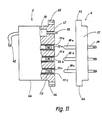
- a plug-in device 4 can also be used, in which the contact means 38, 53 are of the "increased safety" type of protection in order to establish the electrical connection between the module housing 3 and the module rack 2.
- Such a connector device is shown schematically in FIGS. 11 and 12 light, the same reference numerals being used for components already described, insofar as they recur here.
- 11 and 12 in turn contains a part 5 to be held in the module carrier 2 between the support rails 13 and 14, consisting of a base body 46 with an integrally molded base plate 47 and the attachment extensions 65 and 66.
- the base plate 47 contains three cylindrical bores 111a ... 111c, in which the sockets 53a ... 53c are arranged in a floating manner.
- the sockets 53a ... 53c spring back only slightly in relation to the flat front side of the base plate 47 and are held axially immovably.
- each of the sockets 52a ... 53c contains a multiplicity of contact points 112 which can be moved resiliently largely independently of one another within a certain range and which make contact with the plug pin 38a ... 38c to be inserted.
- the socket 53a shown enlarged there, which is essentially formed by a cylindrical piece of pipe with an internal width of approx. 2 mm, contains a circumferential groove 114 just behind its front insertion opening 113, which is formed in the inner circumferential surface of the socket 53a is pierced and which extends in the longitudinal direction over a considerable distance, but has only a comparatively small radial depth.
- this groove 114 is a multi-slit, approximately cylindrical Metallic contact piece 115 is used, the axial extent of which is slightly greater than the axial extent of the groove 114, so that the contact piece 115 bulges convexly in the direction of the longitudinal axis of the socket 53a due to the shape given before the insertion.
- the clear width of the contact piece 115 which is supported at its front ends on the axially located flanks of the groove 114 with respect to the socket 53a, is less than the clear width of the socket 53a in the remaining cylindrical region or less than the outer diameter of the pin 38a to be inserted.
- the tube-like bent contact piece 115 which is provided at 116 with a continuous longitudinal slot, is provided with a multiplicity of closed slots 117 on the edges, which between them projecting contact lamellae or contact strips limit which form the contact points 112.
- these contact lamellae or contact points 112 are connected in one piece to two strips 118, 119 running in the circumferential direction, these two strips 118, 119 being interrupted only in the area of the continuous slot 116.
- the two strips 118, 119 running in the circumferential direction are slotted or notched several times from their axially outer edge, so that tongues 119, 121 which are resilient and extend in the axial direction result independently of one another. on the flanks of the groove 114 support and via which the contact of the contact piece 115 with the base body of the socket 53a comes about.
- the multi-pole electrical switch 58 is provided, the actuator 59 of which projects through the front plate 47 in the direction of the part 6 to be inserted.
- the switch 58 is in turn flameproof and its switching paths are in series with the sockets 53a ... 53c, so that when the switch 58 is not actuated, the sockets 53a ... 53c are switched off and have no connection to the conductors of the cable 62.
- the arrangement between the actuation stroke of the switch 58 and the plugging or separating movement between the two parts 5 and 6 is such that, for example, when the two parts 5 and 6 are plugged together, the first one on the outer circumferential surface is smooth Make electrical contact pins 38a ... 38c with the contact blades 112 electrical contact and thus also with the sockets 53a ... 53c before the actuator 59 comes into engagement with the part 6 in order to switch the flameproof switch 58 in the on position convict.
- the contact points 112 which can be moved independently of one another, in the socket 53a ... 53c, they can also be arranged on the plug pins 38a ... 38c, for which purpose a contact piece is fundamentally suitable, which, like the contact piece 115, is, however, suitable bulges convexly or barrel-shaped outwards from the plug pin.
- the connector pin 38a ... 38c Execute so-called brush connector, in which the connector pin 38a ... 38c is formed by a plurality of individually movable spring tongues. In the latter two cases, the bushing 53a ... 53c can be designed as a simple, smooth-walled piece of pipe.
Applications Claiming Priority (2)
| Application Number | Priority Date | Filing Date | Title |
|---|---|---|---|
| DE3632676 | 1986-09-26 | ||
| DE19863632676 DE3632676A1 (de) | 1986-09-26 | 1986-09-26 | Explosionsgeschuetztes modulgehaeuse |
Publications (4)
| Publication Number | Publication Date |
|---|---|
| EP0261307A2 true EP0261307A2 (fr) | 1988-03-30 |
| EP0261307A3 EP0261307A3 (en) | 1989-10-11 |
| EP0261307B1 EP0261307B1 (fr) | 1993-02-03 |
| EP0261307B2 EP0261307B2 (fr) | 1998-12-02 |
Family
ID=6310378
Family Applications (1)
| Application Number | Title | Priority Date | Filing Date |
|---|---|---|---|
| EP87106856A Expired - Lifetime EP0261307B2 (fr) | 1986-09-26 | 1987-05-12 | Boítier modulaire protégé des explosions |
Country Status (4)
| Country | Link |
|---|---|
| US (1) | US4796159A (fr) |
| EP (1) | EP0261307B2 (fr) |
| JP (1) | JPS6384196A (fr) |
| DE (2) | DE3632676A1 (fr) |
Cited By (3)
| Publication number | Priority date | Publication date | Assignee | Title |
|---|---|---|---|---|
| DE19838492A1 (de) * | 1998-08-25 | 2000-03-09 | Stahl R Schaltgeraete Gmbh | Explosionsgeschützte Steckverbindungsanordnung |
| WO2011134770A2 (fr) * | 2010-04-29 | 2011-11-03 | R. Stahl Schalgeräte Gmbh | Carte de circuits imprimés pourvue d'un boîtier partiel encapsulé résistant à la pression |
| IT201700067928A1 (it) * | 2017-06-19 | 2018-12-19 | Nuovo Pignone Tecnologie Srl | Sistema di controllo per turbomacchina per aree pericolose |
Families Citing this family (50)
| Publication number | Priority date | Publication date | Assignee | Title |
|---|---|---|---|---|
| US4875861A (en) * | 1987-04-29 | 1989-10-24 | Hewlett-Packard Company | Mass interconnect system |
| DE3800077A1 (de) * | 1988-01-05 | 1989-07-13 | Bosch Gmbh Robert | Dezentrale ein/ausgabebaugruppe fuer elektronische steuerungen |
| US4908715A (en) * | 1988-03-29 | 1990-03-13 | Magnetic Peripherals Inc. | Disk drive unit |
| US5144517A (en) * | 1989-10-20 | 1992-09-01 | Pepperl + Fuchs, Inc. | Intrinsically safe barrier device |
| US5149281A (en) * | 1991-09-24 | 1992-09-22 | Teltronics, Inc. | Test enabling terminal enclosure apparatus and method |
| DE4233108A1 (de) * | 1992-10-02 | 1994-04-07 | Fernsprech Und Signalbau Gmbh | Sicherheitskoppelglied |
| US5410446A (en) * | 1993-09-10 | 1995-04-25 | Cooper Industries, Inc. | Circuit breaker explosion stress absorber |
| US5580282A (en) * | 1994-01-14 | 1996-12-03 | Emerson Electric Co. | Sealable shaped connector block for a terminal assembly |
| US5941846A (en) * | 1995-03-13 | 1999-08-24 | Alaris Medical Systems, Inc. | Method and apparatus for power connection in a modular patient care system |
| US5610802A (en) * | 1995-05-23 | 1997-03-11 | Zb B Technologies, Inc. | Compact energy storage system |
| DE19636119A1 (de) * | 1996-09-06 | 1998-03-12 | Teves Gmbh Alfred | Steckverbindung zur Herstellung eines feuchtigkeitsdichten elektrischen Übergangs |
| JPH10132122A (ja) * | 1996-10-25 | 1998-05-22 | Aisin Seiki Co Ltd | 電磁弁ユニット |
| DE29622180U1 (de) * | 1996-12-20 | 1998-04-23 | Hansen & Reinders Gmbh | Schaltvorrichtungen wie Schütze |
| US6015197A (en) * | 1998-02-28 | 2000-01-18 | 3Com Corp. | Protective grommet apparatus and method |
| DE19810350C2 (de) * | 1998-03-10 | 2001-03-08 | Samson Ag | Feldgerät der Zündschutzart der druckfesten Kapselung |
| US6239365B1 (en) * | 1999-05-20 | 2001-05-29 | Mcevers Douglas W. | Sealable electrical outlet enclosure |
| US6309231B1 (en) * | 1999-09-02 | 2001-10-30 | Litton Precision Products International, Inc. | High current male and female power connector assembly |
| US6556447B2 (en) * | 2000-03-01 | 2003-04-29 | Endress + Hauser Flowtec Ag | Electronic apparatus with an enclosure |
| EP1158845A1 (fr) * | 2000-05-25 | 2001-11-28 | Lucent Technologies Inc. | Arrangement de composants permettant de tenir les tolérances requises |
| US7319191B2 (en) * | 2001-11-01 | 2008-01-15 | Thermo Fisher Scientific Inc. | Signal adapter |
| US6680434B2 (en) * | 2001-12-29 | 2004-01-20 | Hon Hai Precision Ind. Co., Ltd. | Terminal locating means assembly |
| GB0213705D0 (en) * | 2002-06-14 | 2002-07-24 | Powerlogic Internat Bv | Electrical connectors |
| DE10356985A1 (de) * | 2003-12-05 | 2005-07-07 | Cooper Crouse-Hinds Gmbh | Datenübertragungseinrichtung |
| FR2864423B1 (fr) * | 2003-12-23 | 2006-04-07 | Sagem | Dispositif a composants electroniques integres muni d'une cloison de separation de zones. |
| US7005576B2 (en) * | 2004-07-12 | 2006-02-28 | Joy Mm Delaware, Inc. | Permissible controller cover resistant to fastener breakage |
| US7063574B2 (en) * | 2004-10-13 | 2006-06-20 | Power Logic Holdings Ag | Installation coupler |
| DE102005032808A1 (de) * | 2004-12-13 | 2007-01-18 | Krohne Ag | Meßgerät |
| US7130176B2 (en) * | 2004-12-23 | 2006-10-31 | Lucent Technologies Inc. | Protective enclosures and related methods |
| US7097515B2 (en) * | 2005-01-19 | 2006-08-29 | Fmc Technologies, Inc. | Subsea electrical connector |
| RU2450403C2 (ru) * | 2006-01-24 | 2012-05-10 | Фишер Контролз Интернешнел Ллс | Взрывозащищенное устройство, содержащее незаземленный ограничитель напряжения |
| DE102006009827B4 (de) * | 2006-03-01 | 2013-08-08 | KROHNE Meßtechnik GmbH & Co. KG | Nichteigensicher gespeistes Meßgerät |
| DE102006052717A1 (de) * | 2006-11-08 | 2008-05-15 | Cooper Crouse-Hinds Gmbh | Steckgehäusemodul |
| US7626826B2 (en) * | 2007-01-31 | 2009-12-01 | Sun Microsystems, Inc. | Expansion card carrier and method for assembling the same |
| US7588448B2 (en) * | 2007-03-30 | 2009-09-15 | Ball-It Oy | Airtight electrical socket |
| EP2034501A1 (fr) * | 2007-09-07 | 2009-03-11 | Eaton Electric B.V. | Dispositif de commutation échangeable rapidement dans un système de commutation de moyenne tension |
| CN101945557B (zh) * | 2010-09-14 | 2012-07-04 | 三一重型装备有限公司 | 防爆电控箱 |
| CN201975619U (zh) * | 2011-02-28 | 2011-09-14 | 广东明家科技股份有限公司 | 一种插座 |
| DE102013104627B3 (de) * | 2013-05-06 | 2014-09-25 | R. Stahl Schaltgeräte GmbH | Anordnung aus einem druckfest gekapselten Gehäuse und einer Temperiervorrichtung und Verfahren zu deren Überwachung |
| DE102013111212A1 (de) * | 2013-10-10 | 2015-04-16 | R.Stahl Schaltgeräte GmbH | Sicherheitsschaltung für ein explosionsgeschütztes Gehäuse und Verfahren zu deren Betrieb |
| CN104494608B (zh) * | 2014-11-26 | 2017-02-01 | 中车南京浦镇车辆有限公司 | 轨道车辆特殊电器件安装结构 |
| WO2017087575A1 (fr) * | 2015-11-16 | 2017-05-26 | Aegex Technologies, Llc | Dispositif mobile à sécurité intrinsèque |
| CA3016912C (fr) | 2016-03-10 | 2023-10-24 | Eaton Intelligent Power Limited | Enceinte antideflagrante ayant des moyens de maintien et de protection de trajectoire de flamme |
| JP2018154194A (ja) * | 2017-03-16 | 2018-10-04 | 三菱自動車工業株式会社 | 車載機器の保護構造 |
| EP3579671B1 (fr) * | 2018-06-05 | 2023-03-15 | R. STAHL Schaltgeräte GmbH | Boîtier du type de protection à blindage résistant à la pression (antidéflagrant) |
| DE102018251785A1 (de) * | 2018-12-28 | 2020-07-02 | Eaton Intelligent Power Limited | Schalt- und/oder Verteilervorrichtung |
| US11469546B2 (en) | 2020-09-29 | 2022-10-11 | Western Technology, Inc. | Electrical connector system |
| DE102020127795A1 (de) | 2020-10-22 | 2022-04-28 | Turck Holding Gmbh | Modulträger im Bereich des sekundären Explosionsschutzes |
| CN112490878B (zh) * | 2020-12-07 | 2022-09-23 | 深圳市旭能达电气科技有限公司 | 具有防爆功能的高低压开关柜 |
| DE102021105218A1 (de) * | 2021-03-04 | 2022-09-08 | Marquardt Gmbh | Schaltmodul ausgebildet mit einer abgedichteten Schnittstelle |
| USD1006276S1 (en) | 2021-08-06 | 2023-11-28 | Western Technology, Inc. | Portable industrial light |
Citations (2)
| Publication number | Priority date | Publication date | Assignee | Title |
|---|---|---|---|---|
| EP0096652A2 (fr) * | 1982-06-08 | 1983-12-21 | Siemens Aktiengesellschaft | Installation de commutation anti-grisou comportant une gaine pour barres omnibus |
| EP0112258A2 (fr) * | 1982-12-21 | 1984-06-27 | Legrand | Socle pour prise de courant de sécurité notamment pour atmosphère explosive |
Family Cites Families (9)
| Publication number | Priority date | Publication date | Assignee | Title |
|---|---|---|---|---|
| US3904812A (en) * | 1973-08-10 | 1975-09-09 | Wagner Electric Corp | Logic module |
| US4213018A (en) * | 1978-06-06 | 1980-07-15 | Crouse-Hinds Company | Explosion-proof contact assembly and method of forming the same |
| US4229403A (en) * | 1979-02-01 | 1980-10-21 | S&C Electric Company | Method of assembling a fault limiter by molding a rigid housing about a non-rigid subassembly |
| US4216349A (en) * | 1979-06-29 | 1980-08-05 | General Signal Corporation | Fill control for sealing chamber in drainable enclosure for explosion-proof electrical system |
| US4399487A (en) * | 1980-09-12 | 1983-08-16 | Siemens Ag | Insulated plug-in module |
| US4591949A (en) * | 1982-06-29 | 1986-05-27 | Lahr Roy J | Modular patchboard for electrical devices |
| US4510553A (en) * | 1983-01-24 | 1985-04-09 | Burroughs Corporation | Electromechanical assembly for aligning, discharging, and sequentially engaging conductors of a P.C. board with a backplane |
| IN164043B (fr) * | 1984-05-21 | 1988-12-31 | Siemens Ag | |
| US4664281A (en) * | 1985-10-15 | 1987-05-12 | Killark Electric Manufacturing Co. | Explosion proof enclosure |
-
1986
- 1986-09-26 DE DE19863632676 patent/DE3632676A1/de not_active Withdrawn
-
1987
- 1987-05-12 DE DE8787106856T patent/DE3783985D1/de not_active Expired - Lifetime
- 1987-05-12 EP EP87106856A patent/EP0261307B2/fr not_active Expired - Lifetime
- 1987-07-15 JP JP62175011A patent/JPS6384196A/ja active Pending
- 1987-09-10 US US07/095,561 patent/US4796159A/en not_active Expired - Lifetime
Patent Citations (2)
| Publication number | Priority date | Publication date | Assignee | Title |
|---|---|---|---|---|
| EP0096652A2 (fr) * | 1982-06-08 | 1983-12-21 | Siemens Aktiengesellschaft | Installation de commutation anti-grisou comportant une gaine pour barres omnibus |
| EP0112258A2 (fr) * | 1982-12-21 | 1984-06-27 | Legrand | Socle pour prise de courant de sécurité notamment pour atmosphère explosive |
Cited By (7)
| Publication number | Priority date | Publication date | Assignee | Title |
|---|---|---|---|---|
| DE19838492A1 (de) * | 1998-08-25 | 2000-03-09 | Stahl R Schaltgeraete Gmbh | Explosionsgeschützte Steckverbindungsanordnung |
| WO2011134770A2 (fr) * | 2010-04-29 | 2011-11-03 | R. Stahl Schalgeräte Gmbh | Carte de circuits imprimés pourvue d'un boîtier partiel encapsulé résistant à la pression |
| WO2011134770A3 (fr) * | 2010-04-29 | 2012-06-28 | R. Stahl Schalgeräte Gmbh | Carte de circuits imprimés pourvue d'un boîtier partiel encapsulé résistant à la pression |
| IT201700067928A1 (it) * | 2017-06-19 | 2018-12-19 | Nuovo Pignone Tecnologie Srl | Sistema di controllo per turbomacchina per aree pericolose |
| EP3418506A1 (fr) * | 2017-06-19 | 2018-12-26 | Nuovo Pignone Tecnologie SrL | Système de commande de turbomachine destinés à des zones dangereuses |
| CN109139134A (zh) * | 2017-06-19 | 2019-01-04 | 诺沃皮尼奥内技术股份有限公司 | 涡轮机 |
| CN109139134B (zh) * | 2017-06-19 | 2023-02-24 | 诺沃皮尼奥内技术股份有限公司 | 涡轮机 |
Also Published As
| Publication number | Publication date |
|---|---|
| EP0261307A3 (en) | 1989-10-11 |
| DE3632676A1 (de) | 1988-03-31 |
| EP0261307B2 (fr) | 1998-12-02 |
| JPS6384196A (ja) | 1988-04-14 |
| DE3783985D1 (de) | 1993-03-18 |
| US4796159A (en) | 1989-01-03 |
| EP0261307B1 (fr) | 1993-02-03 |
Similar Documents
| Publication | Publication Date | Title |
|---|---|---|
| EP0261307B1 (fr) | Boîtier modulaire protégé des explosions | |
| DD292105A5 (de) | Schaltvorrichtung mit geschuetzten unterbrechern | |
| EP1108273B1 (fr) | Ensemble connecteur male-femelle anti-explosion | |
| DE3734293A1 (de) | Elektromagnetische schaltvorrichtung mit austauschbaren schaltern | |
| DE3321497A1 (de) | Anordnung zum anschluss von hilfsleitungen an ein schaltgeraet oder eine schaltgeraetekombination | |
| EP0079016B1 (fr) | Connexion enfichable avec pont de contact interrupteur | |
| DE19627481C2 (de) | Elektrische Schalt- und Sicherungsvorrichtung | |
| DE3720751C2 (de) | Elektrische Verbinderanordnung | |
| DE19509474C2 (de) | Elektrische Schaltanlage | |
| DE3220839C2 (de) | Explosions- oder schlagwettergeschützte Steckvorrichtung | |
| DE2829721C3 (de) | Mosaikbaustein für Schalt- und Meldewarten | |
| EP0399205B1 (fr) | Indicateur de position pour un connecteur enfichable antidéflagrant | |
| DE102014007352A1 (de) | Überspannungsschutzeinrichtung mit mindestens einem Überspannungsschutzgerät | |
| EP0787376B1 (fr) | Installation electrique de distribution haute tension a sectionneur de puissance, a blindage metallique | |
| DE4111956A1 (de) | Mehrpolige elektrische anschlussvorrichtung | |
| EP0080646B1 (fr) | Socle pour un relais miniature | |
| EP0367903A2 (fr) | Pièce de connexion femelle pour la réalisation simultanée de connexions à basse et haute intensité | |
| DE3924032C1 (en) | Switch for opening and closing electrical circuits or lines - has fastening clamps for electrical conductors and housing for switch insert | |
| DE2757967A1 (de) | Elektrischer verbinder | |
| EP1032005B1 (fr) | Installation électrique | |
| DE3309837C2 (fr) | ||
| DE2232322A1 (de) | Programmierbare schaltungsvorrichtung fuer flachdraht-flachkabelverbindungen | |
| DE19514768C2 (de) | Prozeßstecker | |
| EP0339492B1 (fr) | Dispositif pour connecter facultativement des lignes électriques | |
| DE2541692C2 (de) | Bauteil für Verteiler in Fernmelde-, insbesondere Fernsprechanlagen |
Legal Events
| Date | Code | Title | Description |
|---|---|---|---|
| PUAI | Public reference made under article 153(3) epc to a published international application that has entered the european phase |
Free format text: ORIGINAL CODE: 0009012 |
|
| AK | Designated contracting states |
Kind code of ref document: A2 Designated state(s): DE FR GB IT |
|
| PUAL | Search report despatched |
Free format text: ORIGINAL CODE: 0009013 |
|
| AK | Designated contracting states |
Kind code of ref document: A3 Designated state(s): DE FR GB IT |
|
| 17P | Request for examination filed |
Effective date: 19891122 |
|
| 17Q | First examination report despatched |
Effective date: 19920629 |
|
| GRAA | (expected) grant |
Free format text: ORIGINAL CODE: 0009210 |
|
| AK | Designated contracting states |
Kind code of ref document: B1 Designated state(s): DE FR GB IT |
|
| ITF | It: translation for a ep patent filed |
Owner name: JACOBACCI CASETTA & PERANI S.P.A. |
|
| REF | Corresponds to: |
Ref document number: 3783985 Country of ref document: DE Date of ref document: 19930318 |
|
| GBT | Gb: translation of ep patent filed (gb section 77(6)(a)/1977) |
Effective date: 19930302 |
|
| ET | Fr: translation filed | ||
| PLBI | Opposition filed |
Free format text: ORIGINAL CODE: 0009260 |
|
| 26 | Opposition filed |
Opponent name: ENDRESS + HAUSER FLOWTEC AG Effective date: 19931022 |
|
| PLAW | Interlocutory decision in opposition |
Free format text: ORIGINAL CODE: EPIDOS IDOP |
|
| PLAW | Interlocutory decision in opposition |
Free format text: ORIGINAL CODE: EPIDOS IDOP |
|
| PUAH | Patent maintained in amended form |
Free format text: ORIGINAL CODE: 0009272 |
|
| STAA | Information on the status of an ep patent application or granted ep patent |
Free format text: STATUS: PATENT MAINTAINED AS AMENDED |
|
| 27A | Patent maintained in amended form |
Effective date: 19981202 |
|
| AK | Designated contracting states |
Kind code of ref document: B2 Designated state(s): DE FR GB IT |
|
| GBTA | Gb: translation of amended ep patent filed (gb section 77(6)(b)/1977) | ||
| ITF | It: translation for a ep patent filed |
Owner name: JACOBACCI & PERANI S.P.A. |
|
| ET3 | Fr: translation filed ** decision concerning opposition | ||
| REG | Reference to a national code |
Ref country code: GB Ref legal event code: IF02 |
|
| PGFP | Annual fee paid to national office [announced via postgrant information from national office to epo] |
Ref country code: FR Payment date: 20060519 Year of fee payment: 20 |
|
| PGFP | Annual fee paid to national office [announced via postgrant information from national office to epo] |
Ref country code: GB Payment date: 20060522 Year of fee payment: 20 |
|
| PGFP | Annual fee paid to national office [announced via postgrant information from national office to epo] |
Ref country code: IT Payment date: 20060531 Year of fee payment: 20 Ref country code: DE Payment date: 20060531 Year of fee payment: 20 |
|
| REG | Reference to a national code |
Ref country code: GB Ref legal event code: PE20 |
|
| PG25 | Lapsed in a contracting state [announced via postgrant information from national office to epo] |
Ref country code: GB Free format text: LAPSE BECAUSE OF EXPIRATION OF PROTECTION Effective date: 20070511 |