EP0261307A2 - Modular casing protected against explosion - Google Patents
Modular casing protected against explosion Download PDFInfo
- Publication number
- EP0261307A2 EP0261307A2 EP87106856A EP87106856A EP0261307A2 EP 0261307 A2 EP0261307 A2 EP 0261307A2 EP 87106856 A EP87106856 A EP 87106856A EP 87106856 A EP87106856 A EP 87106856A EP 0261307 A2 EP0261307 A2 EP 0261307A2
- Authority
- EP
- European Patent Office
- Prior art keywords
- module housing
- plug
- housing according
- bore
- pin
- Prior art date
- Legal status (The legal status is an assumption and is not a legal conclusion. Google has not performed a legal analysis and makes no representation as to the accuracy of the status listed.)
- Granted
Links
Images


Classifications
-
- H—ELECTRICITY
- H05—ELECTRIC TECHNIQUES NOT OTHERWISE PROVIDED FOR
- H05K—PRINTED CIRCUITS; CASINGS OR CONSTRUCTIONAL DETAILS OF ELECTRIC APPARATUS; MANUFACTURE OF ASSEMBLAGES OF ELECTRICAL COMPONENTS
- H05K7/00—Constructional details common to different types of electric apparatus
- H05K7/14—Mounting supporting structure in casing or on frame or rack
- H05K7/1438—Back panels or connecting means therefor; Terminals; Coding means to avoid wrong insertion
- H05K7/1452—Mounting of connectors; Switching; Reinforcing of back panels
- H05K7/1454—Alignment mechanisms; Drawout cases
-
- H—ELECTRICITY
- H05—ELECTRIC TECHNIQUES NOT OTHERWISE PROVIDED FOR
- H05K—PRINTED CIRCUITS; CASINGS OR CONSTRUCTIONAL DETAILS OF ELECTRIC APPARATUS; MANUFACTURE OF ASSEMBLAGES OF ELECTRICAL COMPONENTS
- H05K7/00—Constructional details common to different types of electric apparatus
- H05K7/14—Mounting supporting structure in casing or on frame or rack
- H05K7/1461—Slidable card holders; Card stiffeners; Control or display means therefor
-
- H—ELECTRICITY
- H05—ELECTRIC TECHNIQUES NOT OTHERWISE PROVIDED FOR
- H05K—PRINTED CIRCUITS; CASINGS OR CONSTRUCTIONAL DETAILS OF ELECTRIC APPARATUS; MANUFACTURE OF ASSEMBLAGES OF ELECTRICAL COMPONENTS
- H05K3/00—Apparatus or processes for manufacturing printed circuits
- H05K3/22—Secondary treatment of printed circuits
- H05K3/28—Applying non-metallic protective coatings
- H05K3/284—Applying non-metallic protective coatings for encapsulating mounted components
Definitions
- the invention relates to an explosion-proof module housing for electrical and / or electronic assemblies with the features of the preamble of claim 1.
- Explosion-proof housings for electronic assemblies are known from the Siemens catalog MP 29, part 10, June 1984, page 10/14, which contain a sand-filled chamber in which the circuit board with the electronic components is housed.
- the housing In order to make the electrical connections with the sand-encapsulated printed circuit board, the housing also contains a connection space which is of the "increased safety" type of protection and contains, for example, screw terminals for the connection wiring.
- Firmly connected cables lead from these screw terminals into the sand-filled chamber, where they are connected to the printed circuit board.
- the cable duct to the sand-filled chamber only needs to be designed according to IP 54.
- This structure is quite simple in itself and has the particular advantage that, because of the sand encapsulation, the housing only has to have small wall thicknesses, which are considerably smaller than in the case of housings which have the same volume in the protection class "pressure resistant" Encapsulation ".
- the sand filling improves the heat dissipation from the interior of the housing compared to the air filling in a flameproof housing. The electronic components can therefore be operated with higher power dissipation in this housing.
- the system or the corresponding part is therefore shut down for a relatively long period of time during troubleshooting or fault elimination, since the power supply is also switched off for the other module housings which are functioning properly. Not only must those parts of the system that are connected to the same power supply as the module to be replaced be shut down, but also those parts from which or to which signal lines lead that are no longer considered intrinsically safe in the sense of DIN EN 50020, although under Under certain circumstances, the system could continue to be operated at least to a limited extent even if the defective electronic assembly was removed.
- the electrical connections are made via a connector device that is designed to be explosion-proof, the connector device can be disconnected at any time without special electrical measures being otherwise required.
- the connection and disconnection of such a connector device is much faster than opening and restoring screwed electrical connections. Even if the system has to be shut down for any other reason to remove the module housing with the module to be replaced, the switch-off time is considerably shorter than with screwed connections.
- This pressure-resistant encapsulation can be achieved simply by the other part of the plug-in connection device containing a hole at the corresponding point, which together with the plug pin forms an ignition-proof gap, while the electrical contact point for the plug pin, based on the direction of insertion of the connector, behind the hole.
- the wall of the bore consists of electrical, non-conductive material. This contact point can be formed by a socket into which the plug pin finally penetrates.
- the plug pins for the formation of the ignition-proof gap have a relatively large length and, on the other hand, the sockets also take up space in the radial direction, it is expedient if the connector pin has an enlarged diameter in the region of the resulting ignition-proof gap, compared with that at its front End lying section that penetrates into the socket when inserted. In this way, the outer diameter of the socket can become almost equal to the outer diameter of the plug pin at the thickest point, while on the other hand a sufficient strength is obtained.
- switch means In order to meet the IP 54 protection requirement when the connector is disconnected, it is either possible to use switch means to de-energize the live sockets or plug pins, or to cover the sockets with automatically closing cover means.
- the covering means can be formed by one or more slides, which are mounted so as to be longitudinally displaceable transversely to the longitudinal axis of the bores for the bushings and contain openings corresponding to the pattern of the bores, so that the bores are closed in one slider position and the bores are released in the other slider position , wherein the actuation of the slider or slides takes place when the two parts of the connector device are plugged together.
- the pin closing the bore is not to be made of insulating material but of electrically conductive material, it is possible to place the bushing opposite the gap which is resistant to ignition set back limiting bore and to hold the slidable pin between the bore and the socket so that the pin makes electrical contact in one position with the socket, while in the other end position the electrical connection is interrupted while the pin is actuated done by the connector pin.
- a very simple locking possibility consists in attaching a membrane made of elastic material in front of the holes, which is slotted or cut in the area of the holes, such that the plug pins penetrate through the membrane into the holes or sockets when the parts of the plug connection device are plugged together can while the diaphragm returns to its original position when the connector pins are pulled to close the holes to IP 54.
- the new module housing is preferably used in a subrack that contains one or more pairs of guide members for the module housing in a frame, which receive the guide members when the module housing is inserted, the part of the module housing assigned to the module housing being inserted when the module housing is inserted Plug connection device comes to rest, the complementary part of the plug connection device is arranged.
- unprotected plug connection devices can also be held for this purpose, via which the intrinsically safe connections are made.
- the subrack together with the explosion-proof module housings, forms a module plug-in system into which largely any module housing can be inserted or from which this module housing can be removed without having to switch off voltages for reasons of explosion protection.
- the part of the plug connection device accommodated in the subrack either contains a connection space of increased security for the connection of the lines or the lines are cast in a known manner in this part of the plug connection device in an explosion-proof manner.
- the contact means of the plug-in connection device In addition to the pressure-resistant encapsulation of the contact means of the plug-in connection device, it is also possible to design the contact means in the type of protection "increased safety" according to DIN EN 50019 "e" in order to obtain an easily replaceable module housing.
- a switch in the "flameproof enclosure” type of protection is inevitably provided at least in that part of the connector device, the contact means of which would otherwise be under voltage after the two parts have been separated from one another. The switch disconnects the contact means.
- the spatial arrangement is such that the switches only close when the electrical connection is already established when the parts are put together between the contact means.
- the contact path formed by mutually assigned contact means of the two parts contains a multiplicity of contact points, each of which is largely resiliently movable. This ensures that in the current range in each case all contact points never lose the mechanical connection to the other contact means at the same time, which could result in sparks.
- the independently movable contact points can be provided either in the contact means designed as a socket or on the contact means designed as a plug.
- the attachment in the socket has the advantage of better protection for these resilient contact points, which are filigree in view of the necessary miniaturization and therefore require protection.
- Possible movable contact points are both lamellae which are formed on a correspondingly slotted sleeve and, for example, tuft plugs, as are otherwise e.g. find application in the high frequency range.
- FIG. 1 is a perspective and schematic or simplified illustration of an explosion-protected module plug-in system 1 which has a rack 2 and explosion-protected module housings 3 which can be pushed into the rack, only one of which is illustrated.
- the electrical connection between the subrack 2 and the module plug-in housing 3 takes place for the so-called "non-intrinsically safe" circuits via a two-part plug-in connection device 4 with a part 5 held in the subrack 2 and a part 6 attached to the module housing 3, both of which are plugged together for the contact materials in it form a pressure-resistant encapsulation according to DIN EN 50018.
- the intrinsically safe circuits are connected via a commercially available connector strip attached to the module housing 3, for example according to DIN 41612 or DIN 41617 or the like. is executed. When plugged in, this plug connector 7 makes contact in a socket connector fitted in the rack 2, which is also commercially available and is not shown for reasons of clarity.
- the subrack 2 contains a frame 8 with two side walls 9 and 11 which are connected to one another via a total of four support rails or struts 12, 13 and 14 which run parallel and at a distance from one another and are perpendicular to the side walls 9 and 11; the front lower mounting rail is not recognizable for reasons of illustration.
- the mounting rails 12 to 14 are screwed by means of screws 15 to the two side walls 9 and 11, namely the two mounting rails 12 and 13 on the top or top edge of the side walls 9 and 11, while the other two mounting rails, of which only the mounting rail 14 is visible, are arranged on the underside.
- the support rails 12, 13, 14 serve to hold guide rails 16 and 17 which, as the pair 16 and 17 show, contain guide grooves 18 and 19 which are open towards one another and aligned with one another.
- the guide rails 16 and 17 are screwed to the support rails 12, 13, 14 with screws 21, in such a way that they run parallel and at a distance from one another and parallel to the side walls 9, 11.
- 2 additional guide rails 16 ⁇ or 16 ⁇ are fastened in the frame 8 of the subrack with screws 21 ⁇ and 21 ⁇ .
- Corresponding guide rails attached to the underside are in alignment with these guide rails 16 ⁇ , 16 ⁇ , of which only the guide rail 17 ⁇ can be seen.
- the distance between the guide rails 16, 17 corresponds, as shown, to the height of the explosion-proof module housing 3, so that it can be inserted between the guide rails 16, 17 and held transversely to the insertion movement by the latter.
- the explosion-proof module housing 3 is illustrated open.
- This module housing with its two side walls 22, 23, a lower wall 24, an upper wall 25 and a rear wall 26 and a front wall 27 has approximately cuboids shaped shape and defines a chamber 28 in which electronic assemblies 29, which are built on printed circuit boards, are arranged.
- the chamber 28 of the explosion-proof module housing 3 is filled with sand or glass balls 30, so that there is a sand encapsulation for the modules 29 accommodated therein, ie the modules 29 are in the module housing 3 in the type of protection "sand encapsulation" according to DIN EN 50017 "q" protected.
- the walls 22 to 27 can be connected to one another in any way, provided that the connection technology selected in each case fulfills the corresponding protective regulations and the assemblies 29 in the chamber 28 are mechanically protected against dust and splash water in accordance with the protection regulation IP 54. If this protective regulation is observed, it is also ensured that the sand filling 30 remains in the chamber 28 and fulfills its protective function.
- the rear wall 26 of the module housing 3 shown contains two rectangular openings 33 and 34, in which the part 6 of the flameproof encapsulated connector device 4 and the connector strip 7 are inserted, the connector strip 7 also being designed and inserted in such a way that the module housing 3 fulfills the protection requirement IP 54 fulfilled; The same applies to part 6.
- the contact means of the connector strip 7 and the explosion-protected plug connection device 6 are connected to the electronic assemblies 29, either by soldering extensions 35 of the contact means directly into the circuit boards of the assemblies 29 or by means of a free wiring 36 leading from the contact means to the corresponding connection points on the printed circuit boards.
- both the part 6 seated in the module housing 3 and the part 5 of the explosion-protected plug-in connection device screwed into the subrack on the mounting rails 13 and 14 are shown in an enlarged perspective and the internal structure can be seen in this figure.
- part 6 contains an approximately plate-shaped base body 37 made of insulating material, which is produced, for example, in an injection molding process.
- a total of three essentially cylindrical plug pins 38a, 38b, 38c are anchored in the base body 37 in a pressure-tight manner, for example by being inserted into the base body 37 during their manufacture are injected.
- the connector pins consist, at least on their surface, of an electrically highly conductive material and protrude rearward through the base body 37, where they form connecting lugs 39 for the wiring 36. In order to immovably hold the connector pins 38a ...
- the part of the plug pins 38a... 38c projecting outwards with respect to the module housing 3 has two cylindrical sections 41 and 42 which are coaxial to one another but have different diameters, namely the longer section 41 with the larger diameter is the basic body 37 immediately adjacent, while the section 42 with the smaller diameter lies at the free tip of the connector pins 38a ... 38c.
- the group of a total of three connector pins 38a ... 38c is tubularly surrounded by a protective collar 43 which is designed in the manner of a short rectangular tube 43 and is an integral part of the base body 37.
- the protective collar 43 has a depth or length which corresponds to the length of the connector pins 38a ... 38c, ie the connector pins 38a ... 38c slightly tip back with respect to the front edge of the protective collar 43.
- Both the protective collar 43 and the plug pins 38a ... 38c run parallel to the guide strips 31, 32.
- the protective collar 43 does not need to be closed all round, but it can also contain slots if this is more favorable in terms of production technology.
- the part 6 is fastened in the module housing 3 with flanges 43 and 44, which are injection molded onto the base body 37 and, in the assembled state, bear against the rear or inside of the rear wall 26. Bores 45 for fastening screws are provided in the flanges.
- the part 5 of the plug connection device 4 attached to the holding rails 13 and 14 of the module carrier 2 has a housing-like insulating base body 46 with a base plate 47, on the back of which an extension 48 is integrally formed in the manner of a square tube piece.
- the base plate 47 contains cylindrical chambers or openings 49a ... 49c, the number and arrangement of which correspond to the number and the arrangement pattern of the plug pins 38a ... 38c or are mirror-symmetrical to these and extend into the extension 48 where they touch their back are sealed pressure-tight.
- 49c are identical to one another and consist of a first cylindrical section 51, which opens at the front of the part 5, and a second cylindrical section 52 behind it, in each of which an electrical socket 53 floats in the radial direction, but in the longitudinal direction is immovably housed.
- the diameter of the cylindrical section 51 corresponds to the diameter of the associated plug pin 38a ... 38c in the region 41 with the larger diameter, in such a way that when the plug pin 38a ... 38c is inserted into the corresponding chamber 49a ... 49c, between the cylindrical bore 51 and the section 41 there is an ignition-proof gap according to DIN EN 50018.
- the cylindrical section 52 in which socket 53 is located is a pressure-tight encapsulated space when plug pin 38a ... 38c is inserted.
- the base body 46 contains a correspondingly complementary recess 54 for receiving the protective collar 43. Both the recess 54 and the protective collar 43 have no protective function in terms of explosion protection.
- Each socket 53 accommodated in its own cylindrical chamber 49a ... 49c has on its rear side a contact lug 55 which projects into the tubular extension 48, where an electrical connecting line or a connecting line 57 is permanently connected.
- a single-pole or multi-pole microswitch 58 is seated in the main body 46, which is of the "flameproof enclosure” type of protection and whose actuating pin 59 protrudes in the direction of the part 6 to be inserted from the front of the base plate 57 and its connecting lugs 61 are located in the tubular extension 48. Via the microswitch 58, such electrical connections are made which, when the part 6 is pulled out of the part 5, keep the corresponding assigned sockets 53 energized, ie in the illustrated case leads for the sockets 53 in the cylindrical chambers 49a and 49b.
- the explosion-proof electrical connection to the part 5 takes place via a multi-pole cable 62, the individual wires, such as the wire 56, are either soldered or welded directly to a connecting lug 55 of a socket 53 or the individual wires, such as a single wire 63, to corresponding connecting lugs 61 of the microswitch 58 are connected, which is electrically connected to corresponding sockets 53 via other connecting lugs 61 and connecting lines 57.
- the interior of the extension 48 is potted in a known manner after the permanent electrical connections have been made with a synthetic resin compound 64.
- the part 5 is held on the mounting rails 13 and 14, at the point where the part 6 is when the module housing 3 is inserted, so that the electrical connection via the explosion-protected plug-in connection device 4 is established .
- the part can also 6, a microswitch 67 can be held, which is designed in the "flameproof enclosure” type of protection and whose actuating pin 68 protrudes from the base body 37, as shown.
- This microswitch 67 ensures that when part 6 is pulled, that is to say when plug pins 38a to 38c are pulled out of part 5, are de-energized (see Fig. 2 and 3).
- the explosion-proof module housing 3 with its rear wall 26 ahead and the part 6 or the connector strip 7 fastened thereon inserted between the corresponding guide rails 16 and 17 in the frame 8, the connector pins 38a penetrate. ..38c into the cylindrical bores 51 of the associated cylindrical chambers containing the bushings 53, to the extent that the explosion-proof module housing 3 is advanced.
- the sections 41 together with the bores 51 form an explosion-proof explosion-proof gap of sufficient length so that if there are sparks during the subsequent contact arise, the space in which these sparks are generated is already flameproof in the sense of the protection regulation. This contact occurs when the module housing 3 is inserted far enough.
- the plug pins 38a ... 38c penetrate deeper into the sockets 53 with their tapered sections 42.
- the actuating pins 59 and 68 of the microswitches 58 and 67 are also depressed, thereby closing the electrical connections which they interrupt.
- the explosion-proof module housing 3 is fully inserted, the non-intrinsically safe circuits to the electronic assemblies 29 in the module housing 3 are closed via the explosion-protected plug-in connection device 4.
- the electrical connections the intrinsically safe circuits via the connector strip 7 and the corresponding socket strip, which, like part 5, are attached to the rear mounting rails 13 and 14 at the appropriate point.
- the intrinsically safe circuits and also the non-intrinsically safe circuits are interrupted by pulling out the plug connector 7, opening sparks possibly occurring in the cylindrical chambers 49a ... 49c, which are to be regarded as flameproof enclosures, which are caused to the rear by the Potting compound 64 and to the front of part 5 are closed by the ex-gap which is formed between the bore 51 and the corresponding section 41 of the connector pin 38a ... 38c. Since pulling down the actuating pins 68 and 59 stops when the module housing 3 is pulled out, the microswitches 58 and 67 interrupt the electrical connections to the corresponding sockets 53 or plug pins 38a ... 38c, so that these are disconnected from the power supply.
- connection space with increased security can be provided on the rear of the part 5, in which the supply line 62 is clamped with clamping screws.
- the metallic parts of the electrical connector device do not necessarily have to be switched off, but it is also sufficient if they are covered by simple measures. In this case, the electrical switching process is inevitable by separating the plug pin and socket.
- FIGS. 5 to 10 Embodiments in which the sockets are covered after pulling the module housing 3 are shown in FIGS. 5 to 10, the same reference numerals being used for the corresponding parts.
- FIGS. 5 to 10 are greatly simplified and parts 5 and 6 of the connector device are only shown in part. So the connector pins 38 are illustrated with the same diameter throughout and the other measures, such as potting and the like .. are not shown.
- a slide 71 is guided in a longitudinally displaceable manner in the base body 46 and closes the bores 51 when the part 6 is pulled.
- the base body 56 contains a rectangular channel 72 just behind the outer mouth of the bores 51, which runs at right angles to the axes of the bores 51 parallel to one another.
- this channel 72 is a cross-sectionally rectangular, elongated tongue 71 with openings 74 arranged according to the pattern of the bores 51, so that in a position of the tongue 73 in the channel 72 the part of the bores 51 behind the slide 71 is accessible from the front is.
- An actuation piece 75 is integrally formed on the upper part of the tongue 73 and has a beveled actuation surface 76 which faces the part 6 of the plug-in connection device 4.
- the actuating piece 75 is displaceable in a recess 77 in the base body 46, in which is also housed a helical spring 78 which engages on the underside of the actuating piece 75 and biases the slide 71 into a position in which the bores 51 are closed to the outside .
- the openings 74 as shown, are each a short distance above the bores 51.
- the slide 71 springs back into the position shown in FIG. 5 as soon as the part 6 has been pulled and the collar 43 has come free from the actuating piece 75.
- the compression spring 78 pushes the slide 71 upwards into a position in which the openings 74 are offset with respect to the bores 51. These are then closed.
- the bore 51 is closed by a pin 81 made of an insulating material.
- a cup-shaped extension 82 connects to the rear, a closure in the opening thereof screw 83 is screwed in.
- the locking screw 83 can in turn be designed as a connection terminal and contains, for example, an undetectable internal thread, into which a clamping screw 84 can be screwed.
- the locking screw 83 On the end projecting into the cup-shaped part 82, the locking screw 83 carries a centering pin 85, on which a compression spring 86 designed as a coil spring is attached.
- the other end of the coil spring 86 is supported in a cup-shaped extension 87 of the pin 81, so that the compression spring 86 strives to push the pin 81 through the bushing 53 into the bore 51.
- the plug pin 38 pushes the pin 51 in front of it and through the socket 53 into its cup-shaped extension 82 and thus releases the bore 51.
- the pin 38 forms an ignition-proof gap with the bore 51 before the foremost tip of the plug pin 38 makes electrical contact with the socket 53.
- the bushing 53 is set back and a bolt 91 consisting of an electrically conductive material can be pushed back and forth between the bore 51 and the bushing 53.
- the bolt 91 has a shaft 92, which is located in the bore 51 and merges in one piece into an annular collar 93 of larger diameter.
- the ring collar 93 lies against a ring shoulder, which is formed at the transition point from the cylindrical chamber 49, in which the bushing 53 is accommodated, and the bore 51.
- the annular collar 93 carries on its end face opposite the bush 53, on which a compression spring 94 designed as a helical spring is supported, a further cylindrical pin 95 which is intended to penetrate into the bush 53.
- the plug pin 38 when the plug pin 38 penetrates into the bore 51 when the module housing 3 is inserted, the plug pin 38, which comes into engagement with the outer end face of the cylindrical shaft 92, pushes the pin 91 against the action of the spring 94 in front of it.
- the cylindrical shaft 95 penetrates into the socket 53, so that an electrical connection is made from the socket 53 via the pin 91 to the end face of the plug pin 38.
- the compression spring 94 is supported in the interior of the base body 46 on an insulating piece 96 which surrounds the bush 53.
- FIGS. 9 and 10 show, it is possible to close the bores 51 by a membrane 897 made of a rubber-elastic material, which on the side of the base body 46 facing the part 5 is attached in front of the bores 51 and is held there by means of a fastening plate 98.
- the fastening plate 98 contains openings 99 which are aligned with the bores 51 and through which the plug pins 38 can penetrate.
- the membrane 97 is provided with star-shaped incisions 101, so that small triangles are formed which are delimited on two sides by cuts and which are integrally connected to the rest of the membrane 97 on the base side.
- the plug pins When the part 6 is inserted, the plug pins can penetrate the membrane 97 where the star-shaped incisions 101 are made in order to reach the bores 51 located behind them. So that the material of the diaphragm 97 which escapes to the rear is not crushed at the edges of the bore 51, the bores 51 are formed immediately behind the diaphragm 97 with cylindrical recesses 102 which form space for the receding membrane parts.
- the membrane parts return elastically to their starting position, which is illustrated in FIG. 10, and close the bores 51 in accordance with the protection regulation IP 54.
- a plug-in device 4 can also be used, in which the contact means 38, 53 are of the "increased safety" type of protection in order to establish the electrical connection between the module housing 3 and the module rack 2.
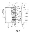
- Such a connector device is shown schematically in FIGS. 11 and 12 light, the same reference numerals being used for components already described, insofar as they recur here.
- 11 and 12 in turn contains a part 5 to be held in the module carrier 2 between the support rails 13 and 14, consisting of a base body 46 with an integrally molded base plate 47 and the attachment extensions 65 and 66.
- the base plate 47 contains three cylindrical bores 111a ... 111c, in which the sockets 53a ... 53c are arranged in a floating manner.
- the sockets 53a ... 53c spring back only slightly in relation to the flat front side of the base plate 47 and are held axially immovably.
- each of the sockets 52a ... 53c contains a multiplicity of contact points 112 which can be moved resiliently largely independently of one another within a certain range and which make contact with the plug pin 38a ... 38c to be inserted.
- the socket 53a shown enlarged there, which is essentially formed by a cylindrical piece of pipe with an internal width of approx. 2 mm, contains a circumferential groove 114 just behind its front insertion opening 113, which is formed in the inner circumferential surface of the socket 53a is pierced and which extends in the longitudinal direction over a considerable distance, but has only a comparatively small radial depth.
- this groove 114 is a multi-slit, approximately cylindrical Metallic contact piece 115 is used, the axial extent of which is slightly greater than the axial extent of the groove 114, so that the contact piece 115 bulges convexly in the direction of the longitudinal axis of the socket 53a due to the shape given before the insertion.
- the clear width of the contact piece 115 which is supported at its front ends on the axially located flanks of the groove 114 with respect to the socket 53a, is less than the clear width of the socket 53a in the remaining cylindrical region or less than the outer diameter of the pin 38a to be inserted.
- the tube-like bent contact piece 115 which is provided at 116 with a continuous longitudinal slot, is provided with a multiplicity of closed slots 117 on the edges, which between them projecting contact lamellae or contact strips limit which form the contact points 112.
- these contact lamellae or contact points 112 are connected in one piece to two strips 118, 119 running in the circumferential direction, these two strips 118, 119 being interrupted only in the area of the continuous slot 116.
- the two strips 118, 119 running in the circumferential direction are slotted or notched several times from their axially outer edge, so that tongues 119, 121 which are resilient and extend in the axial direction result independently of one another. on the flanks of the groove 114 support and via which the contact of the contact piece 115 with the base body of the socket 53a comes about.
- the multi-pole electrical switch 58 is provided, the actuator 59 of which projects through the front plate 47 in the direction of the part 6 to be inserted.
- the switch 58 is in turn flameproof and its switching paths are in series with the sockets 53a ... 53c, so that when the switch 58 is not actuated, the sockets 53a ... 53c are switched off and have no connection to the conductors of the cable 62.
- the arrangement between the actuation stroke of the switch 58 and the plugging or separating movement between the two parts 5 and 6 is such that, for example, when the two parts 5 and 6 are plugged together, the first one on the outer circumferential surface is smooth Make electrical contact pins 38a ... 38c with the contact blades 112 electrical contact and thus also with the sockets 53a ... 53c before the actuator 59 comes into engagement with the part 6 in order to switch the flameproof switch 58 in the on position convict.
- the contact points 112 which can be moved independently of one another, in the socket 53a ... 53c, they can also be arranged on the plug pins 38a ... 38c, for which purpose a contact piece is fundamentally suitable, which, like the contact piece 115, is, however, suitable bulges convexly or barrel-shaped outwards from the plug pin.
- the connector pin 38a ... 38c Execute so-called brush connector, in which the connector pin 38a ... 38c is formed by a plurality of individually movable spring tongues. In the latter two cases, the bushing 53a ... 53c can be designed as a simple, smooth-walled piece of pipe.
Abstract
Ein explosionsgeschütztes Modulgehäuse (3) für elektrische und/oder elektronische Baugruppen enthält wenigstens eine sandgefüllte Kammer (28), in der die Baugruppe untergebracht ist. Die Baugruppe (28) ist auf diese Weise in der Zündschutzart "Sandkapselung" geschützt. An dem Gehäuse (3) sind außerdem Anschlußeinrichtungen (6, 7) für Zuleitungen zu dem Gehäuse vorgesehen. Um das Modulgehäuse (3) jederzeit ohne Abschalten der Anlage, deren Bestandteil das Modulgehäuse (3) ist, einsetzen oder herausnehmen zu können, sind die Anschlußeinrichtungen (6, 7) von einer zweiteiligen Steckverbindungseinrichtung gebildet, die explosionsgeschützt ausgeführt ist und von der ein Teil elektrisch und/oder mit dem Gehäuse (3) verbunden ist. Über diese Steckverbindungseinrichtung sind die nicht eigensicheren Stromkreise geführt.An explosion-proof module housing (3) for electrical and / or electronic assemblies contains at least one sand-filled chamber (28) in which the assembly is housed. The assembly (28) is protected in this way in the "sand encapsulation" type of protection. Connection devices (6, 7) for supply lines to the housing are also provided on the housing (3). In order to be able to insert or remove the module housing (3) at any time without switching off the system, of which the module housing (3) is a part, the connection devices (6, 7) are formed by a two-part connector device, which is designed to be explosion-proof and of which part is electrically and / or connected to the housing (3). The non-intrinsically safe circuits are routed through this connector.
Description
Die Erfindung betrifft ein explosionsgeschütztes Modulgehäuse für elektrische und/oder elektronische Baugruppen mit den Merkmalen des Oberbegriffs des Anspruchs 1.The invention relates to an explosion-proof module housing for electrical and / or electronic assemblies with the features of the preamble of claim 1.
Aus dem Siemens-Katalog MP 29, Teil 10, Juni 1984, Seite 10/14, sind explosionsgeschützte Gehäuse für elektronische Baugruppen bekannt, die eine sandgefüllte Kammer enthalten, in der die Leiterplatte mit den elektronischen Bauelementen untergebracht ist. Um die elektrischen Verbindungen mit der sandgekapselten Leiterplatte herzustellen, enthält das Gehäuse außerdem einen Anschlußraum, der in der Schutzart "Erhöhte Sicherheit" ausgeführt ist und beispielsweise Schraubklemmen für die Anschlußverdrahtung enthält. Von diesen Schraubklemmen führen fest angeschlossene Leitungen in die sandgefüllte Kammer, wo sie an der Leiterplatte angeschlossen sind. Die Leitungsdurchführung zu der sandgefüllten Kammer braucht lediglich nach IP 54 ausgeführt zu sein.Explosion-proof housings for electronic assemblies are known from the Siemens catalog MP 29, part 10, June 1984, page 10/14, which contain a sand-filled chamber in which the circuit board with the electronic components is housed. In order to make the electrical connections with the sand-encapsulated printed circuit board, the housing also contains a connection space which is of the "increased safety" type of protection and contains, for example, screw terminals for the connection wiring. Firmly connected cables lead from these screw terminals into the sand-filled chamber, where they are connected to the printed circuit board. The cable duct to the sand-filled chamber only needs to be designed according to
Dieser Aufbau ist an sich recht einfach und hat insbesondere den Vorteil, daß das Gehäuse wegen der Sandkapselung nur geringe Wandstärken aufweisen muß, die wesentlich geringer sind als bei Gehäusen, die bei gleichem Volumen in der Schutzart "Druckfeste Kapselung" ausgeführt sind. Außerdem verbessert die Sandfüllung die Wärmeableitung aus dem Inneren des Gehäuses, verglichen mit der Luftfüllung bei einem druckfest gekapselten Gehäuse. Die elektronischen Bauelemente können deswegen bei diesem Gehäuse mit höherer Verlustleistung betrieben werden.This structure is quite simple in itself and has the particular advantage that, because of the sand encapsulation, the housing only has to have small wall thicknesses, which are considerably smaller than in the case of housings which have the same volume in the protection class "pressure resistant" Encapsulation ". In addition, the sand filling improves the heat dissipation from the interior of the housing compared to the air filling in a flameproof housing. The electronic components can therefore be operated with higher power dissipation in this housing.
Allerdings hat die Praxis gezeigt, daß hin und wieder elektronische Baugruppen ausfallen und deswegen ausgetauscht werden müssen. Auch im Falle einer Fehler- oder Störungssuche muß unter Umständen die jeweils betrachtete Baugruppe aus der übrigen Schaltung abgetrennt werden. Bei dem bekannten Modulgehäuse muß zu diesem Zweck die Anlage oder zumindest derjenige Teil der Anlage, der das jeweilige Modulgehäuse enthält, spannungslos geschaltet werden, ehe der Anschlußraum"Erhöhte Sicherheit" geöffnet werden darf, um die Zuleitungen darin abzuklemmen.However, practice has shown that electronic assemblies sometimes fail and therefore have to be replaced. Even in the event of a fault or fault search, the module in question may have to be disconnected from the rest of the circuit. In the known module housing, for this purpose the system or at least that part of the system which contains the respective module housing must be disconnected from the power supply before the "increased safety" connection space may be opened in order to disconnect the leads therein.
Bei Anlagen, die die bekannten Modulgehäuse enthalten, ist deswegen während der Fehlersuche oder Fehlerbeseitigung über eine verhältnismäßig große Zeitspanne die Anlage oder der entsprechende Teil stillgelegt, da auch für die anderen, einwandfrei abreitenden Modulgehäuse die Stromversorgung abgeschaltet ist. Dabei müssen nicht nur solche Teile der Anlage stillgelegt sein, die an derselben Stromversorgung hängen wie das auszutauschende Modul, sondern auch diejenigen Teile, von denen oder zu denen Signalleitungen führen, die nicht mehr als eigensichere, im Sinne von DIN EN 50020 gelten, obwohl unter Umständen die Anlage auch bei entfernter fehlerhafter elektronischer Baugruppe zumindest eingeschränkt weiter betrieben werden könnte.In systems which contain the known module housing, the system or the corresponding part is therefore shut down for a relatively long period of time during troubleshooting or fault elimination, since the power supply is also switched off for the other module housings which are functioning properly. Not only must those parts of the system that are connected to the same power supply as the module to be replaced be shut down, but also those parts from which or to which signal lines lead that are no longer considered intrinsically safe in the sense of DIN EN 50020, although under Under certain circumstances, the system could continue to be operated at least to a limited extent even if the defective electronic assembly was removed.
Ausgehend hiervon ist es Aufgabe der Erfindung, ein explosionsgeschütztes Modulgehäuse zu schaffen, das einfacher und schneller aus einer Anlage zu entnehmen und einzusetzen ist, ohne daß aus Gründen des Explosionsschutzes Versorgungsspannungen für die in dem Modulgehäuse untergebrachte Baugruppe oder nicht eigensichere Signalleitungen abgeschaltet werden müssen.Based on this, it is an object of the invention to provide an explosion-proof module housing that can be removed more easily and quickly from a system and is to be used without having to switch off supply voltages for the module accommodated in the module housing or non-intrinsically safe signal lines for reasons of explosion protection.
Diese Aufgabe wird erfindungsgemäß durch das Modulgehäuse mit den Merkmalen des Anspruches 1 gelöst.This object is achieved by the module housing with the features of claim 1.
Dadurch, daß die elektrischen Verbindungen,zumindest soweit sie nicht eigensicher sind, über eine Steckverbindungseinrichtung geführt sind, die explosionsgeschützt ausgeführt ist, kann jederzeit die Steckverbindungseinrichtung getrennt werden, ohne daß ansonsten besondere elektrische Maßnahmen erforderlich sind. Schließlich geht auch das Verbinden und Trennen einer solchen Steckverbindungseinrichtung wesentlich schneller als das Öffnen und Wiederherstellen geschraubter elektrischer Verbindungen. Selbst dann, wenn aus irgendwelchen anderen Gründen zum Herausnehmen des Modulgehäuses mit der auszutauschenden Baugruppe die Anlage stillgesetzt werden muß, ist die Abschaltzeit wesentlich kürzer als bei geschraubten Verbindungen.Characterized in that the electrical connections, at least insofar as they are not intrinsically safe, are made via a connector device that is designed to be explosion-proof, the connector device can be disconnected at any time without special electrical measures being otherwise required. Finally, the connection and disconnection of such a connector device is much faster than opening and restoring screwed electrical connections. Even if the system has to be shut down for any other reason to remove the module housing with the module to be replaced, the switch-off time is considerably shorter than with screwed connections.
Auf diese Weise wird es möglich, auch in ex-gefährdeten Räumen eine Baugruppenstecktechnik zu verwirklichen, wie sie in nicht geschützten Bereichen bereits üblich ist und sich bewährt hat. Diese Stecktechnik läßt sich mit den bekannten Modulgehäusen, die den Anschlußraum "Erhöhte Sicherheit" aufweisen, nicht verwirklichen, selbst dann nicht, wenn die Mehrzahl der Verbindungen eigensicher ist und über eine normale Buchsen- oder Messerleiste nach DIN 41612 oder 41617 od.dgl. geführt werden könnten. Bei dem neuen Modulgehäuse dagegen können derartige Stecker- oder Buchsenleisten sinnvollerweise zusammen mit der explosionsgeschützten Steckverbindungseinrichtung verwendet werden, wobei die eigensicheren Verbindungen zu bzw. von dem Modulgehäuse über die handelsüblichen Kontaktleisten geführt sind.In this way, it is possible to implement a plug-in technology, even in ex-hazardous areas, as is already common in unprotected areas and has proven itself. This plug-in technology cannot be implemented with the known module housings which have the "increased safety" connection space, even if the majority of the connections are intrinsically safe and the like via a normal female or male connector according to DIN 41612 or 41617. could be performed. In the new module housing, on the other hand, such plug or socket strips can usefully be used together with the explosion-proof plug connection device, the intrinsically safe connections to or are guided from the module housing over the commercially available contact strips.
Zur Halterung des Modulgehäuses sind zweckmäßigerweise parallel und mit Abstand voneinander verlaufende Führungsglieder vorgesehen.To hold the module housing, it is expedient to provide parallel and spaced-apart guide members.
Besonders raumsparend werden die Verhältnisse, wenn wenigstens ein Teil der Steckverbindungseinrichtung Steckerstifte enthält, die bei zusammengesteckter Steckverbindungseinrichtung einzeln und für sich druckfest gekapselt sind, da hierdurch sehr kleine zu schützende Volumina entstehen, die erheblich geringere Wandstärken erfordern als größere Volumina, die erforderlich sind, wennn mehrere Steckerstifte gemeinsam druckfest gekapselt sind.Diese druckfeste Kapselung läßt sich einfach dadurch erreichen, daß der andere Teil der Steckverbindungseinrichtung eine Bohrung an der entsprechenden Stelle enthält, die bei eingestecktem Steckerstift mit diesem zusammen einen zünddurchschlagsicheren Spalt bildet, während die elektrische Kontaktstelle für den Steckerstift, bezogen auf die Steckrichtung des Steckers, hinter der Bohrung liegt. Die Wandung der Bohrung besteht dabei aus elektrischem, nicht leitendem Material. Diese Kontaktstelle kann von einer Buchse gebildet sein, in die der Steckerstift schließlich eindringt.The situation becomes particularly space-saving if at least part of the plug-in connection device contains plug pins which are individually and pressure-tightly encapsulated when the plug-in connection device is plugged together, since this results in very small volumes to be protected, which require considerably smaller wall thicknesses than larger volumes which are required if necessary several plug pins are encapsulated together in a pressure-resistant manner. This pressure-resistant encapsulation can be achieved simply by the other part of the plug-in connection device containing a hole at the corresponding point, which together with the plug pin forms an ignition-proof gap, while the electrical contact point for the plug pin, based on the direction of insertion of the connector, behind the hole. The wall of the bore consists of electrical, non-conductive material. This contact point can be formed by a socket into which the plug pin finally penetrates.
Da die Steckerstifte zur Ausbildung des zünddurchschlagsicheren Spaltes eine verhältnismäßig große Länge aufweisen und andererseits auch die Buchsen in radialer Richtung Platz beanspruchen, ist es zweckmäßig wenn der Steckerstift im Bereich des entstehenden zünddurchschlagsicheren Spaltes einen vergrößerten Durchmesser aufweist, verglichen mit dem an seinem Vorder ende liegenden Abschnitt, der im eingesteckten Zustand in die Buchse eindringt. Auf diese Weise kann der Außendurchmesser der Buchse nahezu gleich dem Außendurchmesser des Steckerstiftes an der dicksten Stelle werden, während andererseits eine genügende Festigkeit erhalten wird.Since the plug pins for the formation of the ignition-proof gap have a relatively large length and, on the other hand, the sockets also take up space in the radial direction, it is expedient if the connector pin has an enlarged diameter in the region of the resulting ignition-proof gap, compared with that at its front End lying section that penetrates into the socket when inserted. In this way, the outer diameter of the socket can become almost equal to the outer diameter of the plug pin at the thickest point, while on the other hand a sufficient strength is obtained.
Um bei getrennter Steckverbindungseinrichtung die Schutzvorschrift nach IP 54 zu erfüllen, ist es entweder möglich, Schaltermittel zuverwenden, um die spannungsführenden Buchsen oder Steckerstifte spannungslos zu schalten oder die Buchsen durch selbsttätig schließende Abdeckmittel abzudecken.In order to meet the
Die Abdeckmittel können von einem oder mehreren Schiebern gebildet sein, die quer zu der Längsachse der Bohrungen für die Buchsen längsverschieblich gehaltert sind und Öffnungen entsprechend dem Muster der Bohrungen enthalten, so daß in einer Schieberstellung die Bohrungen verschlossen und in der anderen Schieberstellung die Bohrungen freigegeben sind, wobei die Betätigung des oder der Schieber beim Zusammenstecken der beiden Teile der Steckverbindungseinrichtung erfolgt.The covering means can be formed by one or more slides, which are mounted so as to be longitudinally displaceable transversely to the longitudinal axis of the bores for the bushings and contain openings corresponding to the pattern of the bores, so that the bores are closed in one slider position and the bores are released in the other slider position , wherein the actuation of the slider or slides takes place when the two parts of the connector device are plugged together.
Es ist auch möglich, die Bohrungen durch einen Zapfen zu verschließen, der in der Bohrung sowie der Buchse längsverschieblich gehaltert ist und beim Einschieben des Steckerstiftes in die Buchse zurückgedrückt wird, während beim Ziehen des Steckerstiftes der Zapfen von einer Druckfeder in die Bohrung vorgeschoben wird. Falls der die Bohrung verschließende Zapfen nicht aus Isoliermaterial, sondern aus elektrisch leitendem Material bestehen soll, ist es möglich, die Buchse gegenüber der den zünddurchschlagsicheren Spalt begrenzenden Bohrung zurückzuversetzen und den verschiebbaren Zapfen zwischen der Bohrung und der Buchse hin- und herschiebbar zu haltern, so daß der Zapfen in einer Stellung mit der Buchse elektrischen Kontakt macht, während in der anderen Endstellung die elektrische Verbindung unterbrochen ist, während die Betätigung des Zapfens durch den Steckerstift erfolgt.It is also possible to close the bores by means of a pin which is held in the bore and the socket in a longitudinally displaceable manner and which is pushed back when the plug pin is pushed into the socket, while the pin is pushed into the bore by a compression spring when the plug pin is pulled. If the pin closing the bore is not to be made of insulating material but of electrically conductive material, it is possible to place the bushing opposite the gap which is resistant to ignition set back limiting bore and to hold the slidable pin between the bore and the socket so that the pin makes electrical contact in one position with the socket, while in the other end position the electrical connection is interrupted while the pin is actuated done by the connector pin.
Eine sehr einfache Verschlußmöglichkeit besteht schließlich darin, vor den Bohrungen eine Membrane aus elastischem Material anzubringen, die im Bereich der Bohrungen geschlitzt oder eingeschnitten ist, derart, daß die Steckerstifte beim Zusammenstecken der Teile der Steckverbindungseinrichtung durch die Membrane hindurch in die Bohrungen bzw. Buchsen eindringen können, während bei gezogenen Steckerstiften die Membrane in ihre Ausgangsstellung zurückkehrt, um die Bohrungen nach IP 54 zu verschließen.Finally, a very simple locking possibility consists in attaching a membrane made of elastic material in front of the holes, which is slotted or cut in the area of the holes, such that the plug pins penetrate through the membrane into the holes or sockets when the parts of the plug connection device are plugged together can while the diaphragm returns to its original position when the connector pins are pulled to close the holes to
Das neue Modulgehäuse wird bevorzugt in einem Baugruppenträger verwendet, der in einem Rahmen eines oder mehrere Paare von Führungsgliedern für die Modulgehäuse enthält, die beim Einschieben des Modulgehäuses dessen Führungsglieder aufnehmen, wobei an der Stelle, an der bei eingestecktem Modulgehäuse der dem Modulgehäuse zugeordnete Teil der Steckverbindungseinrichtung zu liegen kommt, der dazu komplementäre Teil der Steckverbindungseinrichtung angeordnet ist. Zusätzlich können hierzu noch ungeschützte Steckverbindungseinrichtungen gehaltert sein, über die die eigensicheren Verbindungen geführt sind.The new module housing is preferably used in a subrack that contains one or more pairs of guide members for the module housing in a frame, which receive the guide members when the module housing is inserted, the part of the module housing assigned to the module housing being inserted when the module housing is inserted Plug connection device comes to rest, the complementary part of the plug connection device is arranged. In addition, unprotected plug connection devices can also be held for this purpose, via which the intrinsically safe connections are made.
Um eine weitgehende Berührungsfreiheit zu bekommen, ist es vorteilhaft, wenn die in dem Baugruppenträger angeordneten Teile der Steckverbindungseinrichtungen ohne Steckerstifte ausgebildet sind.In order to achieve extensive freedom from contact, it is advantageous if the parts of the plug connection devices arranged in the subrack are designed without plug pins.
Der Baugruppenträger bildet zusammen mit den explosionsgeschützten Modulgehäusen ein Modulstecksystem, in das weitgehend beliebig Modulgehäuse eingesteckt oder aus dem diese Modulgehäuse herausgezogen werden können, ohne daß aus Gründen des Explosionsschutzes Spannungen abgeschaltet werden müssen.The subrack, together with the explosion-proof module housings, forms a module plug-in system into which largely any module housing can be inserted or from which this module housing can be removed without having to switch off voltages for reasons of explosion protection.
Der in dem Baugruppenträger untergebrachte Teil der Steckverbindungseinrichtung enthält entweder einen Anschlußraum erhöhter Sicherheit für den Anschluß der Leitungen oder die Leitungen sind in bekannter Weise in diesem Teil der Steckverbindungseinrichtung explosionsgeschützt vergossen.The part of the plug connection device accommodated in the subrack either contains a connection space of increased security for the connection of the lines or the lines are cast in a known manner in this part of the plug connection device in an explosion-proof manner.
Außer der druckfesten Kapselung der Kontaktmittel der Steckverbindungseinrichtung ist es auch möglich, die Kontaktmittel in der Zündschutzart "Erhöhte Sicherheit" nach DIN EN 50019 "e" auszuführen, um ein leicht austauschbares Modulgehäuse zu erhalten. In diesem Falle est zwangsläufig zumindest in demjenigen Teil der Steckverbindungseinrichtung ein Schalter in der Zündschutzart "Druckfeste Kapselung" vorgesehen, dessen Kontaktmittel sonst nach dem Trennen der beiden Teile voneinander unter Spannung stehen würden. Durch den Schalter werden die Kontaktmittel spannungslos geschaltet. Dabei ist die Räumliche Anordnung derart getroffen, daß die Schalter erst schließen, wenn beim Zusammenstecken der Teile zwischen den Kontaktmitteln bereits die elektrische Verbindung hergestellt ist.In addition to the pressure-resistant encapsulation of the contact means of the plug-in connection device, it is also possible to design the contact means in the type of protection "increased safety" according to DIN EN 50019 "e" in order to obtain an easily replaceable module housing. In this case, a switch in the "flameproof enclosure" type of protection is inevitably provided at least in that part of the connector device, the contact means of which would otherwise be under voltage after the two parts have been separated from one another. The switch disconnects the contact means. The spatial arrangement is such that the switches only close when the electrical connection is already established when the parts are put together between the contact means.
Andererseits müssen die Schalter beim Auseinanderziehen der Teile bereits die elektrischen Verbindungen stromlos geschaltet haben, noch ehe die Kontaktmittel außer Eingriff geraten.On the other hand, when the parts are pulled apart, the switches must have already switched off the electrical connections before the contact means become disengaged.
Bei dieser Ausführungsform enthält die durch einander zugeordnete Kontaktmittel der beiden Teile gebildete Kontaktstrecke eine Vielzahl von Kontaktstellen, die jeweils weitgehend unabhängig voneinander federnd bewegbar sind. Damit ist sichergestellt, daß in dem jeweils zulässigen Strombereich nie alle Kontaktstellen gleichzeitig die mechanische Verbindung zu dem anderen Kontaktmittel verlieren, wodurch Funken entstehen könnten.In this embodiment, the contact path formed by mutually assigned contact means of the two parts contains a multiplicity of contact points, each of which is largely resiliently movable. This ensures that in the current range in each case all contact points never lose the mechanical connection to the other contact means at the same time, which could result in sparks.
Die unabhängig voneinander bewegbaren Kontakstellen können dabei wahlweise in dem als Buchse ausgebildeten Kontaktmittel oder auf dem als Stecker ausgebildeten Kontaktmittel vorgesehen sein. Dabei hat allerdings die Anbringung in der Buchse den Vorteil des besseren Schutzes für diese federnden Kontaktstellen, die im Hinblick auf die notwendige Miniaturisierung durchaus filigran sind und deswegen einen Schutz erfordern.The independently movable contact points can be provided either in the contact means designed as a socket or on the contact means designed as a plug. However, the attachment in the socket has the advantage of better protection for these resilient contact points, which are filigree in view of the necessary miniaturization and therefore require protection.
Als bewegliche Kontaktstellen kommen sowohl Lamellen, die an einer entsprechend geschlitzten Hülse ausgebildet sind, in Frage als auch beispielsweise Büschelstecker, wie sie sonst z.B. im Hochfrequenzbereich Anwendung finden.Possible movable contact points are both lamellae which are formed on a correspondingly slotted sleeve and, for example, tuft plugs, as are otherwise e.g. find application in the high frequency range.
In der Zeichnung sind Ausführungsbeispiele des Gegenstandes der Erfindung dargestellt. Es zeigen:
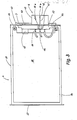
- Fig. 1 einen Baugruppenträger gemäß der Erfindung mit einem explosionsgeschützten Modulgehäuse gemäß der Erfindung, teilweise geschnitten und aufgebrochen, in einer perspektivischen Darstellung,
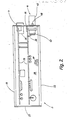
- Fig. 2 das expolosionsgeschützte Modulgehäuse nach Fig. 1 in einer Draufsicht mit abgenommener oberer Wand,
- Fig. 3 das explosionsgeschützte Modulgehäuse nach Fig. 1 mit abgenommener Seitenwand und teilweise aufgebrochenen, an dem Gehäuse gehalterten Teil der explosionsgeschützten Steckvorrichtung,
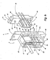
- Fig. 4 die explosionsgeschützte Steckvorrichtung, die in dem Baugruppenträger sowie dem explosionsgeschützten Modulgehäuse nach Fig. 1 zur Anwendung kommt, in einer perspektivischen Darstellung unter Veranschaulichung des inneren Aufbaus,
- Fig. 5 ein weiteres Ausführungsbeispiel der explosionsgeschützten Steckvorrichtung für den Baugruppenträger und das explosionsgeschützte Modulgehäuse nach Fig. 1, wobei die Bohrungen für die Buchsen durch einen Schieber verschließbar sind, in einer schematisierten geschnittenen Seitenansicht,
- Fig. 6 den Schieber der explosionsgeschützten Steckvorrichtung nach Fig. 5, in perspektivischer Darstellung,
- Fig. 7 eine explosionsgeschützte Steckverbindungseinrichtung für das explosionsgeschützte Modulgehäuse und den Baugruppenträger nach Fig. 1, wobei die Bohrung für die Buchse von einem Zapfen aus elektrischem nicht leitendem Material verschließbar ist, geschnitten und in einer schematisierten Seitendarstellung,
- Fig. 8 eine stark schematisierte explosionsgeschützte Steckvorrichtung für das explosionsgeschützte Modulgehäuse und den Baugruppenträger nach Fig. 1, wobei die Bohrung für die Buchse durch einen Zapfen aus elektrisch leitendem Material verschließbar ist, geschnitten und in einer Seitendarstellung,
- Fig. 9 eine explosionsgeschützte Steckverbindungseinrichtung für das explosionsgeschützte Modulgehäuse und den Baugruppenträger nach Fig. 1, wobei die Bohrung für die Buchse von einer entsprechend eingeschnittenen Membrane verschlossen ist, geschnitten und in einer schematisierten Seitenansicht,
- Fig.10 die Membrane für die explosionsgeschützte Steckverbindungseinrichtung nach Fig. 9, in einer perspektivischen Darstellung,
- Fig.11 eine explosionsgeschützte Steckvorrichtung, die in dem Baugruppenträger sowie in dem explosionsgeschützten Modulgehäuse nach Fig. 1 verwendbar und in der Zündschutzart "Erhöhte Sicherheit" ausgeführt ist, in einer Seitenansicht und teilweise aufgebrochen und
- Fig.12 eine vergrößerte Darstellung einer der Steckbuchsen der Steckverbindungseinrichtung nach Fig. 11 in einer teilweise geschnittenen perspektivischen Darstellung.
- 1 is a perspective view of a module rack according to the invention with an explosion-proof module housing according to the invention, partially cut and broken open,
- 2 shows the explosion-proof module housing according to FIG. 1 in a plan view with the top wall removed,
- 3 shows the explosion-protected module housing according to FIG. 1 with the side wall removed and part of the explosion-protected plug-in device which is held open on the housing,
- 4 is a perspective view illustrating the internal structure of the explosion-protected plug-in device which is used in the subrack and the explosion-protected module housing according to FIG. 1,
- 5 shows a further exemplary embodiment of the explosion-protected plug-in device for the module rack and the explosion-protected module housing according to FIG. 1, the bores for the sockets being closable by a slide, in a schematic sectional side view,
- 6 shows the slide of the explosion-proof plug device according to FIG. 5, in a perspective view,
- 7 shows an explosion-protected plug-in connection device for the explosion-protected module housing and the subrack according to FIG. 1, the bore for the socket being closable by a pin made of electrical non-conductive material, cut and in a schematic side view,
- 8 shows a highly schematic explosion-protected plug-in device for the explosion-protected module housing and the subrack according to FIG. 1, the bore for the socket being closable by a pin made of electrically conductive material, cut and in a side view,
- 9 shows an explosion-protected plug-in connection device for the explosion-protected module housing and the subrack according to FIG. 1, the bore for the socket being closed by a correspondingly cut membrane, cut and in a schematic side view,
- 10 shows the membrane for the explosion-proof connector device according to FIG. 9, in a perspective view,
- 11 shows an explosion-protected plug-in device which can be used in the subrack and in the explosion-protected module housing according to FIG. 1 and is of the "increased safety" type of protection, in a side view and partially broken open and
- 12 shows an enlarged illustration of one of the sockets of the connector device according to FIG. 11 in a partially sectioned perspective illustration.
In Fig. 1 ist perspektivisch und schematisiert bzw. vereinfacht ein explosionsgeschütztes Modulstecksystem 1 veranschaulicht, das einen Baugruppenträger 2 sowie in den Baugruppenträger einschiebbare explosionsgeschützte Modulgehäuse 3 aufweist, von denen lediglich eines veranschaulicht ist. Die elektrische Verbindung zwischen dem Baugruppenträger 2 und dem Modulsteckgehäuse 3 erfolgt für die sogenannten "nicht eigensicheren" Stromkreise über eine zweiteilige Steckverbindungseinrichtung 4 mit einem in dem Baugruppenträger 2 gehalterten Teil 5 und einem an dem Modulgehäuse 3 angebrachten Teil 6, die beide im zusammengesteckten Zustand für die darin befindlichen Kontaktmittel eine druckfeste Kapselung nach DIN EN 50018 bilden.1 is a perspective and schematic or simplified illustration of an explosion-protected module plug-in system 1 which has a
Die Verbindungen der eigensicheren Stromkreise erfolgt über eine handelsübliche, an dem Modulgehäuse 3 angebrachte Steckerleiste, die beispielsweise nach DIN 41612 oder DIN 41617 od.dgl. ausgeführt ist. Im eingesteckten Zustand macht diese Steckerleiste 7 in einer in dem Baugruppenträger 2 angebrachten Buchsenleiste Kontakt, die ebenfalls handelsüblich ist und aus Gründen der Übersichtlichkeit nicht dargestellt ist.The intrinsically safe circuits are connected via a commercially available connector strip attached to the
Der Baugruppenträger 2 enthält einen Rahmen 8 mit zwei Seitenwänden 9 und 11, die über insgesamt vier parallel und mit Abstand voneinander verlaufende und auf den Seitenwänden 9 und 11 senkrecht stehenden Tragschienen oder Streben 12, 13, und 14 miteinander verbunden sind; die vordere untere Tragschiene ist aus Darstellungsgründne nicht erkennbar. Die Tragschienen 12 bis 14 sind mittels Schrauben 15 mit den beiden Seitenwänden 9 und 11 verschraubt, und zwar liegen die beiden Tragschienen 12 und 13 an der Oberseite bzw. Oberkante der Seitenwände 9 und 11, während die anderen beiden Tragschienen, von denen nur die Tragschiene 14 sichtbar ist, an der Unterseite angeordnet sind.The
Die Tragschienen 12, 13, 14 dienen der Halterung von Führungsschienen 16 und 17, die, wie das Paar 16 und 17 zeigen, in Richtung aufeinander zu offene und aufeinander ausgerichtete Führungsnuten 18 und 19 enthalten. Die Führungsschienen 16 und 17 sind an den Tragschienen 12, 13, 14 mit Schrauben 21 angeschraubt, und zwar so, daß sie parallel und mit Abstand zueinander und parallel zu den Seitenwänden 9, 11 verlaufen.The support rails 12, 13, 14 serve to hold
Je nach Bedarf sind in dem Rahmen 8 des Baugruppenträgers 2 weitere Führungsschienen 16ʹ oder 16ʺ mit Schrauben 21ʹ und 21ʺ befestigt. Mit diesen Führungsschienen 16ʹ, 16ʺ fluchten entsprechende, an der Unterseite angebrachte Führungsschienen, von denen lediglich die Führungsschiene 17ʹ erkennbar ist.Depending on requirements, 2 additional guide rails 16ʹ or 16ʺ are fastened in the
Der Abstand der Führungsschienen 16, 17 voneinander entspricht, wie gezeigt, der Höhe des explosionsgeschützten Modulgehäuses 3, so daß es zwischen den Führungsschienen 16, 17 einführbar und von diesen quer zur Einsteckbewegung gehalten ist.The distance between the guide rails 16, 17 corresponds, as shown, to the height of the explosion-
In den Fig. 2 und 3 ist das explosionsgeschützte Modulgehäuse 3 geöffnet veranschaulicht. Dieses Modulgehßäuse mit seinen beiden Seitenwänden 22,23, einer unteren Wand 24, einer oberen Wand 25 sowie einer Rückwand 26 und einr Vorderwand 27 hat etwa quader förmige Gestalt und begrenzt eine Kammer 28, in der elektronische Baugruppen 29, die auf Leiterkarten aufgebaut sind, angeordnet sind. Die Kammer 28 des explosionsgeschützten Modulgehäuses 3 ist mit Sand oder Glaskugeln 30 gefüllt, so daß sich für die darin untergebrachten Baugruppen 29 eine Sandkapselung ergibt, d.h. die Baugruppen 29 sind in dem Modulgehäuse 3 in der Zündschutzart "Sandkapselung" nach DIN EN 50017 "q" geschützt. Die Wände 22 bis 27 können in beliebiger Weise miteinander verbunden sein, soweit die jeweils gewählte Verbindungstechnik die entsprechenden Schutzvorschriften erfüllt und die Baugruppen 29 in der Kammer 28 nach der Schutzvorschrift IP 54 mechanisch gegen Staub und Spritzwasser gescnützt sind. Bei Einhaltung dieser Schutzvorschrift wird außerdem sichergestellt, daß die Sandfüllung 30 in der Kammer 28 bleibt und seine Schutzfunktion erfüllt.2 and 3, the explosion-
An der oberen und der unteren Wand 24, 25 sind zwei in Längsrichtung des Modulgehäuses 3 verlaufende Führungsleisten 31, 32 angeformt, die in ihren Abmessungen auf die Führungsnuten 18, 19 in den Führungsschienen 16, 17 abgestimmt sind und in diesen Nuten beim Einstecken des Modulgehäuses in den Baugruppenträger 2 entlanggleiten. Sie sorgen hierbei gleichzeitig dafür, daß beim Einstecken des Modulgehäuses 3 angebrachten Teile 6 und 7 der Steckverbindungseinrichtungen 4 die in dem Baugruppenträger 2 gehalterten Teile 5 in der ricntigen Weise treffen.On the upper and
Die Rückwand 26 des gezeigten Modulgehäuses 3 enthält zwei rechteckige nebeneinanderliegende Öffnungen 33 und 34, in die der Teil 6 der druckfest gekapselten Steckverbindungseinrichtung 4 und die Steckerleiste 7 eingesetzt sind, wobei auch die Steckerleiste 7 so ausgeführt und eingesetzt ist, daß das Modulgehäuse 3 die Schutzvorschrift IP 54 erfüllt; entsprechendes gilt für den Teil 6. Im Inneren des Modulgehäuses 3 sind die Kontaktmittel der Steckerleiste 7 sowie der explosionsgeschützten Steckverbindungseinrichtung 6 mit den elektronischen Baugruppen 29 verbunden, und zwar entweder indem Verlängerungen 35 der Kontaktmittel unmittelbar in die Leiterplatten der Baugruppen 29 eingelötet sind oder mittels einer freien Verdrahtung 36, die von den Kontaktmitteln zu den entsprechenden Anschlußpunkten auf den Leiterplatten führen.The
In Fig. 4 sind sowohl der in dem Modulgehäuse 3 sitzende Teil 6 als auch der in dem Baugruppenträger an den Tragschienen 13 und 14 angeschraubte Teil 5 der explosionsgeschützten Steckverbindungseinrichtung vergrößert perspektivisch dargestellt und es ist in dieser Figur der innere Aufbau erkennbar.4, both the
Hiernach enthält der Teil 6 einen etwa plattenförmigen, aus Isolierstoff bestehenden Grundkörper 37, der beispielsweise in einem Spritzgießvorgang hergestellt ist. In dem Grundkörper 37 sind in dem gezeigten Ausführungsbeispiel insgesamt drei im wesentlichen zylindrische Steckerstifte 38a, 38b, 38c druckdicht verankert, beispielsweise indem sie in den Grundkörper 37 bei deren Herstellung mit einge spritzt sind. Die Steckerstifte bestehen zumindest auf ihrer Oberfläche aus einem elektrisch gut leitenden Material und ragen nach rückwärts durch den Grundkörper 37 hindurch, wo sie Anschlußfahnen 39 für die Verdrahtung 36 bilden. Um die Steckerstifte 38a ... 38c, die rechtwinklig zu dem Grundkörper 37 und damit rechtwinklig zu der Rückwand 26 des Modulgehäuses 3 verlaufen,unverrückbar zu haltern, weisen sie in bekannter Weise in dem in dem Grunkörper 37 eingebetteten Abschnitt Verjüngungen und/oder Verstärkungen auf, die einen formschlüssigen Verbund mit dem Grundkörper 37 ergeben. Der nach außen, bezogen auf das Modulgehäuse 3 hervorstehende Teil der Steckerstifte 38a...38c weist zwei zylindrische Abschnitt 41 und 42 auf, die zueinander koaxial sind, jedoch unterschiedlichen Durchmesser aufweisen, und zwar ist der längere Abschnitt 41 mit dem größeren Durchmesser dem Grundkörper 37 unmittelbar benachbart, während der Abschnitt 42 mit dem kleineren Durchmesser an der freien Spitze der Steckerstifte 38a...38c liegt.Thereafter,
Die Gruppe von insgesamt drei Steckerstiften 38a...38c ist von einem Schutzkragen 43 rohrförmig umgeben, der nach Art eines kurzen Rechteckrohres 43 ausgebildet ist und einstückiger Bestandteil des Grundkörpers 37 ist. Der Schutzkragen 43 hat eine Tiefe bzw. Länge, die der Länge der Steckerstifte 38a...38c entspricht, d.h. die Steckerstifte 38a...38c springen mit ihren Spitzen gegenüber dem vorderen Rand des Schutzkragens 43 geringfügig zurück. Sowohl der Schutzkragen 43 als auch die Steckerstifte 38a...38c verlaufen parallel zu den Führungsleisten 31, 32.The group of a total of three connector pins 38a ... 38c is tubularly surrounded by a
Der Schutzkragen 43 braucht nicht rundum geschlossen zu sein, sondern er kann auch Schlitze enthalten, falls dies fertigungstechnisch günstiger ist.The
Die Befestigung des Teils 6 in dem Modulgehäuse 3 erfolgt mit Flanschen 43 und 44, die an den Grundkörper 37 angespritzt sind und im montierten Zustand an der Rück- oder Innenseite der Rückwand 26 anliegen. In den Flanschen sind Bohrungen 45 für Befestigungsschrauben vorgesehen.The
Der an den Halteschienen 13 und 14 des Modulträgers 2 angebrachte Teil 5 der Steckverbindungseinrichtung 4 weist einen gehäuseartigen isolierenden Grundkörper 46 auf mit einer Grundplatte 47, an deren Rückseite ein Fortsatz 48 nach Art eines Vierkantrohrstückes einstückig angeformt ist. Die Grundplatte 47 enthält zylindrische Kammern oder Öffnungen 49a...49c, die in ihrer Anzahl und Anordnung der Anzahl und dem Anordnungsmuster der Steckerstifte 38a...38c entsprechen bzw. zu diesen spiegelsymmetrisch sind und bis in den Fortsatz 48 reichen, wo sie an ihrer Rückseite druckdicht verschlossen sind. Die zylindrischen Kammern 49a...49c sind untereinander gleich und bestehen aus einem ersten, an der Vorderseite des Teiles 5 mündenden zylindrischen Abschnitt 51 sowie einem zweiten dahinterliegenden zylindrischen Abschnitt 52, in dem jeweils eine elektrische Steckbuchse 53 in radialer Richtung schwimmend, in Längsrichtung jedoch unverschieblich untergebracht ist. Der Durchmesser des zylindrischen Abschnittes 51 entspricht dem Durchmesser des zugehörigen Steckerstiftes 38a...38c im Bereich 41 mit dem größeren Durchmesser, und zwar so, daß wenn der Steckerstift 38a...38c in die entsprechende Kammer 49a...49c eingesteckt ist, sich zwischen der zylindrischen Bohrung 51 und dem Abschnitt 41 ein zünddurchschlagsicherer Spalt nach DIN EN 50018 ergibt. Der zylindrische Abschnitt 52, in dem sich Buchse 53 befindet, ist so bei eingestecktem Steckerstift 38a...38c ein für sich druckfest gekapselter Raum.The
Damit das Zusammenstecken der beiden Teile 5 und 6 nicht durch den Schutzkragen 43 behindert ist, enthält der Grundkörper 46 für die Aufnahme des Schutzkragens 43 eine entsprechend komplementäre Ausnehmung 54. Sowohl die Ausnehmung 54 als auch der Schutzkragen 43 haben keine Schutzfunktion im Sinne eines Explosionsschutzes.So that the plugging together of the two
Jede in einer eigenen zylindrischen Kammer 49a...49c untergebrachte Buchse 53 trägt an ihrer Rückseite eine Kontaktfahne 55, die in den rohrförmigen Fortsatz 48 hineinragt, wo eine elektrische Anschlußleitung oder eine Verbindungsleitung 57 unlösbar angeschlossen ist.Each
Oberhalb der zylindrischen Kammern 49a...49c sitzt in dem Grundkörper 46 ein ein- oder mehrpoliger Mikroschalter 58, der in der Zündschutzart "Druckfeste Kapselung" ausgeführt ist und dessen Betätigungsstift 59 in Richtung auf den einzuführenden Teil 6 aus der Vorderseite der Grundplatte 57 vorragt und dessen Anschlußfahnen 61 sich in dem rohrförmigen Fortsatz 48 befinden. Über den Mikroschalter 58 werden solche elektrischen Verbindungen geführt, die, wenn der Teil 6 aus dem Teil 5 herausgezogen ist, die entsprechenden zugeordneten Buchsen 53 unter Spannung halten, d.h. im veranschaulichten Falle Zuleitungen für die Buchsen 53 in den zylindrischen Kammern 49a und 49b.Above the
Die explosionsgeschützte elektrische Verbindung mit dem Teil 5 geschieht über ein mehrpoliges Kabel 62, dessen einzelne Adern, wie die Ader 56, entweder unmittelbar an eine Anschlußfahne 55 einer Buchse 53 angelötet oder angeschweißt sind oder dessen Einzeladern, wie eine Einzelader 63, an entsprechende Anschlußfahnen 61 des Mikroschalters 58 angeschlossen sind, der über andere Anschlußfahnen 61 und Verbindungsleitungen 57 mit entsprechenden Buchsen 53 elektrisch verbunden ist. Der Innenraum des Fortsatzes 48 ist in bekannter Weise nach dem Herstellen der dauerhaften elektrischen Verbindungen mit einer Kunstharzmasse 64 vergossen.The explosion-proof electrical connection to the
Mit Hilfe von seitlichen Flanschen 65 und 66 ist der Teil 5 an den Tragschienen 13 und 14 gehaltert, und zwar an derjenigen Stelle, an der sich bei eingestecktem Modulgehäuse 3 der Teil 6 befindet, so daß die elektrische Verbindung über die explosionsgeschützte Steckverbindungseinrichtung 4 hergestellt ist.With the help of
Falls die in dem Modulgehäuse 3 untergebrachte Baugruppe 29 ihrerseits Speicher für elektrische Energie enthält, beispielsweise Glättungskondensatoren, die in der Lage sind, Spannungen und Ströme an Steckerstifte 38a bis 38c zu liefern, die außerhalb des als eigensicher angesehenen Stromspannungsbereiches liegen, kann auch in dem Teil 6 ein Mikroschalter 67 gehaltert sein, der in der Zündschutzart "Druckfeste Kapselung" ausgeführt ist und dessen Betätigungsstift 68 aus dem Grundkörper 37, wie gezeigt, hervorsteht. Dieser Mikroschalter 67 sorgt dafür, daß bei gezogenem Teil 6, wenn also die Steckerstifte 38a bis 38c aus dem Teil 5 herausgezogen sind, spannungslos geschaltet sind (siehe Fig. 2 und 3).If the
Wenn bei dem Modulstecksystem 1 nach Fig. 1 das explosionsgeschützte Modulgehäuse 3 mit seiner Rückwand 26 voraus und dem darauf befestigten Teil 6 bzw. der Steckerleiste 7 voraus, zwischen die entsprechenden Führungsschienen 16 und 17 in den Rahmen 8 eingesteckt wird, dringen die Steckerstifte 38a...38c in die zylindrischen Bohrungen 51 der zugehörigen, die Buchsen 53 enthaltenden zylindrischen Kammern ein, in dem Maße, in dem das explosionsgeschützte Modulgehäuse 3 vorgeschoben wird. Noch ehe ein elektrischer Kontakt zwischen den verjüngten Abschnitten 42 der Steckerstifte 38a...38c mit den Steckbuchsen 53 zustandekommt, bilden die Abschnitte 41 zusammen mit den Bohrungen 51 einen zünddurchschlagsicheren ex-Spalt mit ausreichender Länge, so daß, wenn bei der anschließenden Kontaktgabe Funken entstehen, der Raum, in dem diese Funken hervorgerufen werden, bereits im Sinne der Schutzvorschrift druckfest gekapselt ist. Diese Kontaktgabe tritt ein, wenn das Modulgehäuse 3 weit genug eingesteckt ist. Im Verlauf des weiteren Einschiebens dringen die Steckerstifte 38a...38c mit ihren verjüngten Abschnitten 42 tiefer in die Buchsen 53 ein. Gleichzeitig hierbei werden auch die Betätigungsstifte 59 und 68 der Mikroschalter 58 und 67 niedergedrückt, womit die von ihnen unterbrochenen elektrischen Verbindungen geschlossen werden. Wenn das explosionsgeschützte Modulgehäuse 3 vollständig eingesteckt ist, sind über die explosionsgeschützte Steckverbindungseinrichtung 4 die nicht eingensicheren Stromkreise zu den elektronischen Baugruppen 29 in dem Modulgehäuse 3 geschlossen. Gleichzeitig sind auch die elektrischen Verbindungen der eigensicheren Stromkreise über die Steckerleiste 7 und die entsprechende Buchsenleiste hergestellt, die, wie der Teil 5, an den rückwärtigen Tragschienen 13 und 14 an der entsprechenden Stelle befestigt sind.1, the explosion-
Beim Herausziehen des Modulgehäuses 3 werden umgekehrt durch Herausziehen der Steckerleiste 7 die eigensicheren Stromkreise unterbrochen und auch die nicht eigensicheren Stromkreise, wobei eventuell enstehende Öffnungsfunken in den als druckfest gekapselte Räume anzusehenden zylindrischen Kammern 49a... 49c hervorgerufen werden, die zur Rückseite hin durch die Vergußmasse 64 und zu der Vorderseite des Teils 5 hin durch den ex-Spalt verschlossen sind, der zwischen der Bohrung 51 und dem entsprechenden Abschnitt 41 des Steckerstiftes 38a...38c ausgebildet ist. Da beim Herausziehen des Modulgehäuses 3 das Niederdrücken der Betätigungsstifte 68 und 59 aufhört, unterbrechen die Mikroschalter 58 und 67 die elektrischen Verbindungen zu den entsprechenden Buchsen 53 oder Steckerstiften 38a...38c, so daß diese spannungslos geschaltet sind.When the
Ersichtlicherweise müssen vor dem Einsetzen oder dem Entfernen des Modulgehäuses 3 keine zusätzlichen Schalter willkürlich betätigt werden, da sämtliche notwendigen Strom- und Spannungsunterbrechungen selbsttätig beim Ziehen des Modulgehäuses 3 unterbrochen oder beim Einstecken hergestellt werden, wobei die beteiligten Buchsen und Steckerstifte Schalterfunktion übernehmen und der dabei auftretende Schaltvorgang in jeweils druckfest gekapselten Kammern erfolgt.Obviously, no additional switches have to be actuated arbitrarily before inserting or removing the
Anstatt die elektrischen Verbindungen zwischen den Buchsen 53 und der Zuleitung 62 zu vergießen, kann an der Rückseite des Teils 5 ein Anschlußraum erhöhte Sicherheit vorgesehen sein, in dem die Zuleitung 62 mit Klemmschrauben angeklemmt ist.Instead of shedding the electrical connections between the
Um die notwendigen Schutzvorschriften zu erfüllen, müssen nicht notwendigerweise die metallischen Teile der elektrischen Steckverbindungseinrichtung spannungslos geschaltet werden, sondern es genügt auch, wenn sie durch einfache Maßnahmen abgedeckt werden. In diesem Falle erfolgt zwangsläufig der elektrische Schaltvorgang durch das Trennen von Steckerstift und Buchse.In order to comply with the necessary protective regulations, the metallic parts of the electrical connector device do not necessarily have to be switched off, but it is also sufficient if they are covered by simple measures. In this case, the electrical switching process is inevitable by separating the plug pin and socket.
Ausführungsbeispiele, bei denen die Buchsen nach dem Ziehen des Modulgehäuses 3 abgedeckt sind, sind in den Fig. 5 bis 10 dargestellt, wobei für die einander entsprechenden Teile dieselben Bezugszeichen verwendet sind. Außerdem sind die Fig. 5 bis 10 stark vereinfacht und die Teile 5 und 6 der Steckverbindungseinrichtung sind nur ausschnittsweise gezeigt. So sind die Steckerstifte 38 mit durchgehend gleichem Durchmesser veranschaulicht und es sind die übrigen Maßnahmen, wie Vergießen u.dgl.. nicht gezeigt.Embodiments in which the sockets are covered after pulling the
Bei dem Ausführungsbeispiel nach Fig. 5 ist in dem Grundkörper 46 ein Schieber 71 längsverschieblich geführt, der bei gezogenem Teil 6 die Bohrungen 51 verschließt. Zu diesem Zweck enthält der Grundkörper 56 knapp hinter der außenliegenden Mündung der Bohrungen 51 einen rechteckigen Kanal 72, der rechtwinklig zu den Achsen der zueinander parallelen Bohrungen 51 verläuft. In diesem Kanal 72 steckt eine im Querschnitt rechteckige, längliche Zunge 71 mit entsprechend dem Muster der Bohrungen 51 angeordneten Öffnungen 74, so daß in einer Stellung der Zunge 73 in dem Kanal 72 der hinter dem Schieber 71 liegende Teil der Bohrungen 51 von vorne her zugänglich ist.In the embodiment according to FIG. 5, a
Am oberen Teil der Zunge 73 ist ein Betätigungsstück 75 einstückig angeformt, das eine abgeschrägte Betätigungsfläche 76 aufweist, die dem Teil 6 der Steckverbindungseinrichtung 4 zugekehrt ist. Das Betätigungsstück 75 ist in einer Ausnehmung 77 in dem Grundkörper 46 verschiebbar, in den auch eine Schraubenfeder 78 untergebracht ist, die an der Unterseite des Betätigungsstücks 75 angreift und den Schieber 71 in eine Stellung vorspannt, in der die Bohrungen 51 nach außen hin verschlossen sind. In dieser Stellung liegen die Öffnungen 74, wie gezeigt, jeweils ein kurzes Stück oberhalb der Bohrungen 51. Beim Einstecken des Teils 6 in das Teil 5 kommt der Schutzkragen 43 mit der abgeschrägten Fläche 46 in Eingriff, so daß bei einem weiteren Vorschieben das Betätigungsstück 75 in die Ausnehmung 77 eingeschoben wird. Gleichzeitig damit wird auch die Zunge 73 in dem Kanal 72 nach unten geschoben, wobei in der erreichten Endstellung die Öffnungen 74 mit den Bohrungen 51 fluchten und einen freien Durchtritt der Steckerstifte 38 in die Bohrungen 51 ermöglichen.An
Umgekehrt springt der Schieber 71 in die in Fig. 5 gezeigte Lage zurück, sobald der Teil 6 gezogen ist und der Kragen 43 von dem Betätigungsstück 75 freigekommen ist. Hierbei schiebt die Druckfeder 78 den Schieber 71 nach oben in eine Stellung, in der die Öffnungen 74 gegenüber den Bohrungen 51 versetzt sind. Diese sind daraufhin verschlossen.Conversely, the
Bei dem in Fig. 7 gezeigten Ausführungsbeispiel erfolgt das Verschließen der Bohrung 51 durch einen Zapfen 81 aus einem Isolierstoff. An die Buchse 53 schließt sich hierbei nach rückwärts ein becherförmiger Fortsatz 82 an, in dessen Öffnung eine Verschluß schraube 83 eingeschraubt ist. Die Verschlußschraube 83 kann ihrerseits als Anschlußklemme ausgebildet sein und enthält beispielsweise hierfür ein nicht erkennbares Innengewinde, in das eine Klemmschraube 84 einschraubbar ist. Auf der in das becherförmige Teil 82 hineinragenden Stirnseite trägt die Verschlußschraube 83 einen Zentrierzapfen 85, auf dem eine als Schraubenfeder ausgebildete Druckfeder 86 aufgesteckt ist. Das andere Ende der Schraubenfeder 86 stützt sich in einem becherförmigen Fortsatz 87 des Zapfens 81 ab, so daß die Druckfeder 86 bestrebt ist, den Zapfen 81 durch die Buchse 53 in die Bohrung 51 vorzuschieben. Beim Einstecken des Teils 6 in den Teil 5 schiebt der Steckerstift 38 den Zapfen 51 vor sich her und durch die Buchse 53 hindurch in deren becherförmigen Fortsatz 82 und gibt damit die Bohrung 51 frei. Auch hier bildet der Zapfen 38 mit der Bohrung 51 einen zünddurchschlagsicheren Spalt, noch ehe die vorderste Spitze des Steckerstiftes 38 mit der Buchse 53 elektrischen Kontakt macht.In the embodiment shown in FIG. 7, the
Umgekehrt ist bei gezogenem Teil 6 die Bohrung 51 durch den zylindrischen Zapfen 81 verschlossen, der beim Ziehen des Teils 6 von der Druckfeder 86 durch die Buchse 53 hindurch in die Bohrung 51 vorgeschoben wird.Conversely, when the
Bei dem Ausführungsbeispiel nach Fig. 8 ist die Buchse 53 zurückversetzt und zwischen der Bohrung 51 und der Buchse 53 ist ein aus einem elektrisch leitenden Material bestehender Bolzen 91 hin- und herschiebbar. Der Bolzen 91 weist einen Schaft 92 auf, der in der Bohrung 51 sich befindet und einstückig in einen Ringbund 93 größeren Durchmessers übergeht. Der Ringbund 93 legt sich an eine Ring schulter an, die an der Übergangsstelle von der zylindrischen Kammer 49, in der die Buchse 53 untergebracht ist, und der Bohrung 51 ausgebildet ist. Der Ringbund 93 trägt auf seiner der Buchse 53 gegenüberliegenden Stirnseite, an der sich eine als Schraubenfeder ausgebildete Druckfeder 94 abstützt, einen weiteren zylindrischen Zapfen 95, der dazu bestimmt ist, in die Buchse 53 einzudringen.In the exemplary embodiment according to FIG. 8, the
Wenn bei dieser Ausführungsform der Steckerstift 38 beim Einschieben des Modulgehäuses 3 in die Bohrung 51 eindringt, schiebt der Steckerstift 38, der mit der außenliegenden Stirnfläche des zylindrischen Schaftes 92 in Eingriff kommt, den Zapfen 91 gegen die Wirkung der Feder 94 vor sich her. Hierbei dringt der zylindrische Schaft 95 in die Buchse 53 ein, so daß eine elektrische Verbindung von der Buchse 53 über den Zapfen 91 zu der Stirnseite des Steckerstiftes 38 hergestellt wird.In this embodiment, when the
Beim Herausziehen des Steckerstiftes 38 infolge eines Trennens der Teile 5 und 6 zieht die Druckfeder 98 den zylindrischen Zapfen 95 wieder aus der Buchse 53 heraus, so daß keine elektrische Verbindung mehr zu dem Zapfen 91 besteht.When pulling out the
Die Druckfeder 94 stützt sich im Inneren des Grundkörpers 46 auf einem Isolierstück 96 ab, das die Buchse 53 umgibt.The
Schließlich ist es, wie die Fig. 9 und 10 zeigen, möglich, die Bohrungen 51 durch eine Membrane 897 aus einem gummielastischen Material zu verschließen, die auf der dem Teil 5 zugekehrten Seite des Grundkörpers 46 vor den Bohrungen 51 angebracht ist und dort mittels einer Befestigungsplatte 98 gehalten ist. Die Befestigungsplatte 98 enthält mit den Bohrungen 51 fluchtende Öffnungen 99, durch die hindurch die Steckerstifte 38 eindringen können. An denjenigen Stellen, an denen sich hinter der Membrane 97 die Bohrungen 51 befinden, ist die Membrane 97, wie Fig. 10 zeigt, mit sternförmig verlaufenden Einschnitten 101 versehen, so daß kleine Dreiecke entstehen, die an zwei Seiten von Schnitten begrenzt sind und die an der Grundseite mit dem Rest der Membrane 97 einstückig verbunden sind. Beim Einstecken des Teils 6 können die Steckerstifte die Membrane 97 dort, wo die sternförmigen Einschnitte 101 angebracht sind, durchdringen, um in die dahinter gelegenen Bohrungen 51 zu gelangen. Damit das dabei nach hinten ausweichende Material der Membrane 97 nicht an den Rändern der Bohrung 51 zerquetscht wird, sind die Bohrungen 51 unmittelbar hinter der Membrane 97 mit zylindrischen Ausnehmungen 102 ausgebildet, die Platz für die zurückweichenden Membranteile bilden.Finally, as FIGS. 9 and 10 show, it is possible to close the
Sobald der Teil gezogen ist, kehren die Membranteile elastisch in ihre Ausgangsstellung zurück, die in Fig. 10 veranschaulicht ist und verschließen die Bohrungen 51 gemäß der Schutzvorschrift IP 54.As soon as the part has been pulled, the membrane parts return elastically to their starting position, which is illustrated in FIG. 10, and close the
Anstelle einer Steckvorrichtung mit druckfester Kapselung der Kontaktmittel kann auch eine Steckvorrichtung 4 verwendet werden, bei der die Kontaktmittel 38, 53 in der Zündschutzart "Erhöhte Sicherheit" ausgeführt sind, um die elektrische Verbindung zwischen dem Modulgehäuse 3 und dem Baugruppenträger 2 herzustellen. Eine derartige Steckverbindungseinrichtung ist in den Fig. 11 und 12 schematisch veranschau licht, wobei für bereits beschriebene Bauteile, soweit sie hier wiederkehren, dieselben Bezugszeichen verwendet sind.Instead of a plug-in device with flameproof encapsulation of the contact means, a plug-in
Die Steckvorrichtung nach den Fig. 11 und 12 enthält wiederum einen in dem Modulträger 2 zwischen den Tragschienen 13 und 14 zu halternden Teil 5, bestehend aus einem Grundkörper 46 mit einer einstückig angeformten Grundplatte 47 und den Befestigungsfortsätzen 65 und 66. Die Grundplatte 47 enthält drei zylindrische Bohrungen 111a...111c, in denen schwimmend die Steckbuchsen 53a...53c angeordnet sind. Die Steckbuchsen 53a...53c springen nur geringfügig gegenüber der planen Vorderseite der Grundplatte 47 zurück und sind axial unverschieblich gehalten.11 and 12 in turn contains a
Um die Zündschutzart "Erhöhte Sicherheit" zu erfüllen, enthält jede der Steckbuchsen 52a...53c eine Vielzahl von Kontaktstellen 112, die innerhalb eines gewissen Bereiches weitgehend unabhängig voneinander federnd bewegbar sind und mit dem einzuführenden Steckerstift 38a...38c Kontakt machen.In order to meet the "increased safety" type of protection, each of the sockets 52a ... 53c contains a multiplicity of
Die Ausbildung der Vielzahl federnd elastischer Kontaktstellen ist aus Fig. 12 ersichtlich. Wie zu erkennen ist, enthält die dort vergrößert veranschaulichte Steckbuchse 53a , die im wesentlichen von einem zylindrischen Rohrstück mit einer lichten Weite von ca. 2 mm gebildet ist, knapp hinter ihrer vorderen Einführöffnung 113 eine umlaufende Nut 114, die in der Innenumfangsfläche der Buchse 53a eingestochen ist und die sich in deren Längsrichtung über ein beträchtliches Stück erstreckt, jedoch nur eine vergleichsweise geringe radiale Tiefe aufweist. In dieser Nut 114 ist ein mehrfach geschlitztes, etwa zylinderförmiges metallisches Kontaktstück 115 eingesetzt, dessen axiale Erstreckung geringfügig größer ist als die axiale Erstreckung der Nut 114, so daß sich das Kontaktstück 115 aufgrund der vor dem Einsetzen gegebenen Gestalt in Richtung auf die Längsachse der Buchse 53a konvex vorwölbt. Die lichte Weite des Kontaktstücks 115, das sich an seinen stirnseitig befindlichen Enden an den in Achsrichtung, bezogen auf die Buchse 53a gelegenen Flanken der Nut 114 abstützt, ist geringer als die lichte Weite der Buchse 53a in dem übrigen zylindrischen Bereich bzw. auch kleiner als der Außendurchmesser des einzuführenden Steckerstiftes 38a.The formation of the plurality of resiliently elastic contact points can be seen from FIG. 12. As can be seen, the socket 53a, shown enlarged there, which is essentially formed by a cylindrical piece of pipe with an internal width of approx. 2 mm, contains a
Um die mehrfachen und unabhängig voneinander bewegbaren Kontaktstellen zu erhalten, ist das rohrartig zusamengebogene Kontaktstück 115, das bei 116 mit einem durchgehenden Längsschlitz versehen ist, mit einer Vielzahl von randseitig geschlossenen Schlitzen 117 versehen, die zwischen sich in Richtung auf das Innere vorstehende Kontaktlamellen oder Kontaktstreifen begrenzen, die die Kontaktstellen 112 bilden. Infolge der nicht durchgehenden Schlitze 117 hängen diese Kontaktlamellen oder Kontaktstellen 112 einstückig an zwei in Umfangsrichtung verlaufenden Streifen 118, 119 einstückig zusammen, wobei diese beiden Streifen 118, 119 lediglich im Bereich des durchgehenden Schlitzes 116 unterbrochen sind.In order to obtain the multiple and independently movable contact points, the tube-like
Um auch mehrfach federnde Kontaktstellen mit der Buchse 53a herzustellen, sind die beiden in Umfangsrichtung verlaufenden Streifen 118, 119 von ihrer axial außen liegenden Kante her mehrfach eingeschlitzt oder eingekerbt, so daß sich voneinander unabhängig federnde und in axialer Richtung erstreckende Zungen 119, 121 ergeben, die sich an den Flanken der Nut 114 abstützen und über die der Kontakt des Kontaktstücks 115 mit dem Grundkörper der Steckbuchse 53a zustandekommt.In order to also produce multiple resilient contact points with the bushing 53a, the two
Beim Einstecken des Steckerstiftes 38a kommt die Außenumfangsfläche des Steckerstiftes 38 mit den Kontaktlamellen 112 in Berührung und drückt diese radial nach außen. Dabei bewegt sich jede der Kontaktlamellen 112 weitgehend unabhängig von den benachbarten Kontaktlamellen und kehrt auch beim Herauziehen des Steckerstiftes 38a wieder unabhängig von den übrigen Kontaktlamellen 112 federnd in die Ausgangsstellung zurück, wie sie in den Fig. 11 und 12 gezeigt ist.When the plug pin 38a is inserted, the outer circumferential surface of the
Damit bei dieser Ausführungsform der Steckverbindungseinrichtung 4 die Stromunterbrechung nicht durch ein Trennen der Kontaktmittel 38, 53 zustandekommt, was zündfähige Funken hervorrufen könnte, ist, wie bei dem vorherigen Beispiel nach Fig. 4,zumindest in demjenigen Teil der Steckverbindungsrichtung 4, der zu Spannungsquellen hin verbunden ist, in Fig. 11 beispielsweise dem Teil 5, der mehrpolige elektrische Schalter 58 vorgesehen, dessen Betätigungsglied 59 durch die Frontplatte 47 in Richtung auf den einzusteckenden Teil 6 ragt. Der Schalter 58 ist wiederum druckfest gekapselt und seine Schaltstrecken liegen in Serie zu den Buchsen 53a...53c, so daß bei unbetätigtem Schalter 58 die Buchsen 53a...53c spannungslos geschaltet sind und keine Verbindung zu den Leitern des Kabels 62 haben.So that in this embodiment of the
Die Anordnung zwischen dem Betätigungshub des Schalters 58 und der Steck- bzw. Trennbewegung zwischen den beiden Teilen 5 und 6 ist so getroffen, daß beispielsweise beim Zusammenstecken der beiden Teile 5 und 6 zunächst die auf der Außenumfangsfläche glattzylindri schen Steckerstifte 38a...38c mit den Kontaktlamellen 112 elektrischen Kontakt und damit auch mit den Steckbuchsen 53a...53c elektrischen Kontakt herstellen, ehe das Betätigungsglied 59 mit dem Teil 6 in Eingriff kommt, um den druckfest gekapselten Schalter 58 in die Einschaltstellung zu überführen. Die Kontaktgabe zwischen den Kontaktmitteln 38 und 53 erfüllt bereits die Vorschrift "Erhöhte Sicherheit", wenn schließlich durch das weitere Zusammenstecken der beiden Teile 5 und 6 das Betätigungsglied 59 von dem weiter angenäherten Teil 6 betätigt wird und damit die Schaltstrecken des Schalters 58 schließen, um die Stromkreise über die Schaltmittel 38, 53 herzustellen.The arrangement between the actuation stroke of the
Umkehrt werden sämtliche Stromkreise über die Kontaktstrecken, die von den Kontaktmitteln 38 und 53 gebildet sind, unterbrochen, noch ehe beim Auseinanderziehen der beiden Teile 5 und 6 die Steckerstifte 38a...38c von den Kontaktstellen 112 der Buchsen 53a...53c freigekommen sind, so daß in jedem Falle bei geschlossenen Kontaktstrecken des druckfest gekapselten Schalters 58 zwischen den Buchsen 53a...53c und den zugeordneten Steckerstiften 38a...38c elektrische Verbindungen bestehen, die die Vorschriften für die Zündschutzart "Erhöhte Sicherheit" erfüllen.Conversely, all circuits are interrupted via the contact paths which are formed by the contact means 38 and 53, before the plug pins 38a ... 38c are released from the contact points 112 of the sockets 53a ... 53c when the two
Anstatt die unabhängig voneinander bewegbaren Kontaktstellen 112 in der Buchse 53a...53c unterzubringen, können diese auch auf den Steckerstiften 38a...38c angeordnet sein, wozu sich grundsätzlich ein Kontaktstück eignet, das, ähnlich wie das Kontaktstück 115 gestaltet ist, sich jedoch von dem Steckerstift konvex oder tonnenförmig nach außen wölbt. Schließlich besteht die Möglichkeit, den Steckerstift 38a...38c als sogenannten Büschelstecker auszuführen, bei dem der Steckerstift 38a...38c von einer Vielzahl einzeln beweglicher Federzungen gebildet ist. In beiden letztgenannten Fällen kann die Buchse 53a...53c als einfaches glattwandiges Rohrstück ausgeführt sein.Instead of accommodating the contact points 112, which can be moved independently of one another, in the socket 53a ... 53c, they can also be arranged on the plug pins 38a ... 38c, for which purpose a contact piece is fundamentally suitable, which, like the
Claims (32)
Applications Claiming Priority (2)
| Application Number | Priority Date | Filing Date | Title |
|---|---|---|---|
| DE19863632676 DE3632676A1 (en) | 1986-09-26 | 1986-09-26 | EXPLOSION-PROTECTED MODULE HOUSING |
| DE3632676 | 1986-09-26 |
Publications (4)
| Publication Number | Publication Date |
|---|---|
| EP0261307A2 true EP0261307A2 (en) | 1988-03-30 |
| EP0261307A3 EP0261307A3 (en) | 1989-10-11 |
| EP0261307B1 EP0261307B1 (en) | 1993-02-03 |
| EP0261307B2 EP0261307B2 (en) | 1998-12-02 |
Family
ID=6310378
Family Applications (1)
| Application Number | Title | Priority Date | Filing Date |
|---|---|---|---|
| EP87106856A Expired - Lifetime EP0261307B2 (en) | 1986-09-26 | 1987-05-12 | Modular casing protected against explosion |
Country Status (4)
| Country | Link |
|---|---|
| US (1) | US4796159A (en) |
| EP (1) | EP0261307B2 (en) |
| JP (1) | JPS6384196A (en) |
| DE (2) | DE3632676A1 (en) |
Cited By (3)
| Publication number | Priority date | Publication date | Assignee | Title |
|---|---|---|---|---|
| DE19838492A1 (en) * | 1998-08-25 | 2000-03-09 | Stahl R Schaltgeraete Gmbh | Explosion-proof connector assembly |
| WO2011134770A2 (en) * | 2010-04-29 | 2011-11-03 | R. Stahl Schalgeräte Gmbh | Printed circuit board with partial housing encapsulated in a pressure-resistant manner |
| IT201700067928A1 (en) * | 2017-06-19 | 2018-12-19 | Nuovo Pignone Tecnologie Srl | CONTROL SYSTEM FOR TURBOMACCHINA FOR DANGEROUS AREAS |
Families Citing this family (50)
| Publication number | Priority date | Publication date | Assignee | Title |
|---|---|---|---|---|
| US4875861A (en) * | 1987-04-29 | 1989-10-24 | Hewlett-Packard Company | Mass interconnect system |
| DE3800077A1 (en) * | 1988-01-05 | 1989-07-13 | Bosch Gmbh Robert | DECENTRALIZED IN / OUTPUT ASSEMBLY FOR ELECTRONIC CONTROLLERS |
| US4908715A (en) * | 1988-03-29 | 1990-03-13 | Magnetic Peripherals Inc. | Disk drive unit |
| US5144517A (en) * | 1989-10-20 | 1992-09-01 | Pepperl + Fuchs, Inc. | Intrinsically safe barrier device |
| US5149281A (en) * | 1991-09-24 | 1992-09-22 | Teltronics, Inc. | Test enabling terminal enclosure apparatus and method |
| DE4233108A1 (en) * | 1992-10-02 | 1994-04-07 | Fernsprech Und Signalbau Gmbh | Safety coupling device, esp. for explosive environments - contains device with intrinsically safe components connected via cable and plug connector to device with encapsulated components |
| US5410446A (en) * | 1993-09-10 | 1995-04-25 | Cooper Industries, Inc. | Circuit breaker explosion stress absorber |
| US5580282A (en) * | 1994-01-14 | 1996-12-03 | Emerson Electric Co. | Sealable shaped connector block for a terminal assembly |
| US5941846A (en) * | 1995-03-13 | 1999-08-24 | Alaris Medical Systems, Inc. | Method and apparatus for power connection in a modular patient care system |
| US5610802A (en) * | 1995-05-23 | 1997-03-11 | Zb B Technologies, Inc. | Compact energy storage system |
| DE19636119A1 (en) * | 1996-09-06 | 1998-03-12 | Teves Gmbh Alfred | Plug connection to create a moisture-proof electrical transition |
| JPH10132122A (en) * | 1996-10-25 | 1998-05-22 | Aisin Seiki Co Ltd | Solenoid valve unit |
| DE29622180U1 (en) * | 1996-12-20 | 1998-04-23 | Hansen & Reinders Gmbh | Switching devices such as contactors |
| US6015197A (en) * | 1998-02-28 | 2000-01-18 | 3Com Corp. | Protective grommet apparatus and method |
| DE19810350C2 (en) * | 1998-03-10 | 2001-03-08 | Samson Ag | Field device of the type of protection of the flameproof enclosure |
| US6239365B1 (en) * | 1999-05-20 | 2001-05-29 | Mcevers Douglas W. | Sealable electrical outlet enclosure |
| US6309231B1 (en) * | 1999-09-02 | 2001-10-30 | Litton Precision Products International, Inc. | High current male and female power connector assembly |
| US6556447B2 (en) * | 2000-03-01 | 2003-04-29 | Endress + Hauser Flowtec Ag | Electronic apparatus with an enclosure |
| EP1158845A1 (en) * | 2000-05-25 | 2001-11-28 | Lucent Technologies Inc. | Arrangement of components while maintaining required tolerances |
| US7319191B2 (en) * | 2001-11-01 | 2008-01-15 | Thermo Fisher Scientific Inc. | Signal adapter |
| US6680434B2 (en) * | 2001-12-29 | 2004-01-20 | Hon Hai Precision Ind. Co., Ltd. | Terminal locating means assembly |
| GB0213705D0 (en) * | 2002-06-14 | 2002-07-24 | Powerlogic Internat Bv | Electrical connectors |
| DE10356985A1 (en) * | 2003-12-05 | 2005-07-07 | Cooper Crouse-Hinds Gmbh | Data communications equipment |
| FR2864423B1 (en) * | 2003-12-23 | 2006-04-07 | Sagem | INTEGRATED ELECTRONIC COMPONENT DEVICE HAVING A ZONE SEPARATION BIN. |
| US7005576B2 (en) * | 2004-07-12 | 2006-02-28 | Joy Mm Delaware, Inc. | Permissible controller cover resistant to fastener breakage |
| US7063574B2 (en) * | 2004-10-13 | 2006-06-20 | Power Logic Holdings Ag | Installation coupler |
| DE102005032808A1 (en) * | 2004-12-13 | 2007-01-18 | Krohne Ag | gauge |
| US7130176B2 (en) * | 2004-12-23 | 2006-10-31 | Lucent Technologies Inc. | Protective enclosures and related methods |
| US7097515B2 (en) * | 2005-01-19 | 2006-08-29 | Fmc Technologies, Inc. | Subsea electrical connector |
| BRPI0707234B1 (en) * | 2006-01-24 | 2018-12-11 | Fisher Controls Int Llc | flameproof appliance and method for operating systems and devices in a hazardous environment |
| DE102006009827B4 (en) * | 2006-03-01 | 2013-08-08 | KROHNE Meßtechnik GmbH & Co. KG | Non-intrinsically powered meter |
| DE102006052717A1 (en) * | 2006-11-08 | 2008-05-15 | Cooper Crouse-Hinds Gmbh | Plug housing module |
| US7626826B2 (en) * | 2007-01-31 | 2009-12-01 | Sun Microsystems, Inc. | Expansion card carrier and method for assembling the same |
| US7588448B2 (en) * | 2007-03-30 | 2009-09-15 | Ball-It Oy | Airtight electrical socket |
| EP2034501A1 (en) * | 2007-09-07 | 2009-03-11 | Eaton Electric B.V. | Quickly exchangeable switching device in fixed type medium voltage switchgear system |
| CN101945557B (en) * | 2010-09-14 | 2012-07-04 | 三一重型装备有限公司 | Anti-explosion electric cabinet |
| CN201975619U (en) * | 2011-02-28 | 2011-09-14 | 广东明家科技股份有限公司 | Socket |
| DE102013104627B3 (en) * | 2013-05-06 | 2014-09-25 | R. Stahl Schaltgeräte GmbH | Arrangement of a flameproof enclosure and a tempering device and method for monitoring thereof |
| DE102013111212A1 (en) * | 2013-10-10 | 2015-04-16 | R.Stahl Schaltgeräte GmbH | Safety circuit for an explosion-proof housing and method of operation thereof |
| CN104494608B (en) * | 2014-11-26 | 2017-02-01 | 中车南京浦镇车辆有限公司 | Special electric device mounting structure of rail car |
| WO2017087575A1 (en) * | 2015-11-16 | 2017-05-26 | Aegex Technologies, Llc | Intrinsically safe mobile device |
| MX2018010538A (en) | 2016-03-10 | 2018-11-09 | Eaton Intelligent Power Ltd | Explosion-proof enclosure with flame path maintenance and protection means. |
| JP2018154194A (en) * | 2017-03-16 | 2018-10-04 | 三菱自動車工業株式会社 | On-vehicle device protection structure |
| EP3579671B1 (en) * | 2018-06-05 | 2023-03-15 | R. STAHL Schaltgeräte GmbH | Housing for pressure-proof enclosure |
| DE102018251785A1 (en) * | 2018-12-28 | 2020-07-02 | Eaton Intelligent Power Limited | Switching and / or distribution device |
| US11469546B2 (en) | 2020-09-29 | 2022-10-11 | Western Technology, Inc. | Electrical connector system |
| DE102020127795A1 (en) | 2020-10-22 | 2022-04-28 | Turck Holding Gmbh | Module carrier in the area of secondary explosion protection |
| CN112490878B (en) * | 2020-12-07 | 2022-09-23 | 深圳市旭能达电气科技有限公司 | High-low voltage switch cabinet with explosion-proof function |
| DE102021105218A1 (en) * | 2021-03-04 | 2022-09-08 | Marquardt Gmbh | Switch module designed with a sealed interface |
| USD1006276S1 (en) | 2021-08-06 | 2023-11-28 | Western Technology, Inc. | Portable industrial light |
Citations (2)
| Publication number | Priority date | Publication date | Assignee | Title |
|---|---|---|---|---|
| EP0096652A2 (en) * | 1982-06-08 | 1983-12-21 | Siemens Aktiengesellschaft | Fire damp-proof switchgear with a bus bar duct |
| EP0112258A2 (en) * | 1982-12-21 | 1984-06-27 | Legrand | Electrical security socket, especially for an explosive atmosphere |
Family Cites Families (9)
| Publication number | Priority date | Publication date | Assignee | Title |
|---|---|---|---|---|
| US3904812A (en) * | 1973-08-10 | 1975-09-09 | Wagner Electric Corp | Logic module |
| US4213018A (en) * | 1978-06-06 | 1980-07-15 | Crouse-Hinds Company | Explosion-proof contact assembly and method of forming the same |
| US4229403A (en) * | 1979-02-01 | 1980-10-21 | S&C Electric Company | Method of assembling a fault limiter by molding a rigid housing about a non-rigid subassembly |
| US4216349A (en) * | 1979-06-29 | 1980-08-05 | General Signal Corporation | Fill control for sealing chamber in drainable enclosure for explosion-proof electrical system |
| US4399487A (en) * | 1980-09-12 | 1983-08-16 | Siemens Ag | Insulated plug-in module |
| US4591949A (en) * | 1982-06-29 | 1986-05-27 | Lahr Roy J | Modular patchboard for electrical devices |
| US4510553A (en) * | 1983-01-24 | 1985-04-09 | Burroughs Corporation | Electromechanical assembly for aligning, discharging, and sequentially engaging conductors of a P.C. board with a backplane |
| IN164043B (en) * | 1984-05-21 | 1988-12-31 | Siemens Ag | |
| US4664281A (en) * | 1985-10-15 | 1987-05-12 | Killark Electric Manufacturing Co. | Explosion proof enclosure |
-
1986
- 1986-09-26 DE DE19863632676 patent/DE3632676A1/en not_active Withdrawn
-
1987
- 1987-05-12 DE DE8787106856T patent/DE3783985D1/en not_active Expired - Lifetime
- 1987-05-12 EP EP87106856A patent/EP0261307B2/en not_active Expired - Lifetime
- 1987-07-15 JP JP62175011A patent/JPS6384196A/en active Pending
- 1987-09-10 US US07/095,561 patent/US4796159A/en not_active Expired - Lifetime
Patent Citations (2)
| Publication number | Priority date | Publication date | Assignee | Title |
|---|---|---|---|---|
| EP0096652A2 (en) * | 1982-06-08 | 1983-12-21 | Siemens Aktiengesellschaft | Fire damp-proof switchgear with a bus bar duct |
| EP0112258A2 (en) * | 1982-12-21 | 1984-06-27 | Legrand | Electrical security socket, especially for an explosive atmosphere |
Cited By (7)
| Publication number | Priority date | Publication date | Assignee | Title |
|---|---|---|---|---|
| DE19838492A1 (en) * | 1998-08-25 | 2000-03-09 | Stahl R Schaltgeraete Gmbh | Explosion-proof connector assembly |
| WO2011134770A2 (en) * | 2010-04-29 | 2011-11-03 | R. Stahl Schalgeräte Gmbh | Printed circuit board with partial housing encapsulated in a pressure-resistant manner |
| WO2011134770A3 (en) * | 2010-04-29 | 2012-06-28 | R. Stahl Schalgeräte Gmbh | Printed circuit board with partial housing encapsulated in a pressure-resistant manner |
| IT201700067928A1 (en) * | 2017-06-19 | 2018-12-19 | Nuovo Pignone Tecnologie Srl | CONTROL SYSTEM FOR TURBOMACCHINA FOR DANGEROUS AREAS |
| EP3418506A1 (en) * | 2017-06-19 | 2018-12-26 | Nuovo Pignone Tecnologie SrL | Turbomachine control system for hazardous areas |
| CN109139134A (en) * | 2017-06-19 | 2019-01-04 | 诺沃皮尼奥内技术股份有限公司 | turbine |
| CN109139134B (en) * | 2017-06-19 | 2023-02-24 | 诺沃皮尼奥内技术股份有限公司 | Turbine engine |
Also Published As
| Publication number | Publication date |
|---|---|
| EP0261307A3 (en) | 1989-10-11 |
| JPS6384196A (en) | 1988-04-14 |
| EP0261307B1 (en) | 1993-02-03 |
| US4796159A (en) | 1989-01-03 |
| DE3632676A1 (en) | 1988-03-31 |
| EP0261307B2 (en) | 1998-12-02 |
| DE3783985D1 (en) | 1993-03-18 |
Similar Documents
| Publication | Publication Date | Title |
|---|---|---|
| EP0261307B1 (en) | Modular casing protected against explosion | |
| DD292105A5 (en) | SWITCHING DEVICE WITH PROTECTED INTERRUPTORS | |
| EP1108273B1 (en) | Explosion-proof plug-in connector | |
| DE3734293A1 (en) | ELECTROMAGNETIC SWITCHING DEVICE WITH INTERCHANGEABLE SWITCHES | |
| DE3321497A1 (en) | ARRANGEMENT FOR CONNECTING AUXILIARY CABLES TO A SWITCHGEAR OR A SWITCHGEAR COMBINATION | |
| EP0079016B1 (en) | Pluggable connection with a switchable contacting bridge | |
| DE19627481C2 (en) | Electrical switch and fuse device | |
| DE3720751C2 (en) | Electrical connector assembly | |
| DE19509474C2 (en) | Electrical switchgear | |
| DE3220839C2 (en) | Explosion-proof or firedamp-proof plug-in device | |
| DE2829721C3 (en) | Mosaic building block for control rooms and message rooms | |
| EP0399205B1 (en) | Position-indicator for an explosion-proof plug-in connector | |
| DE102014007352A1 (en) | Overvoltage protection device with at least one overvoltage protection device | |
| EP0787376B1 (en) | Metal-cladded electrical high-voltage switching installation with a power switch | |
| DE4111956A1 (en) | Multipole electrical circuit board connector - has socket contacts within socket housing cooperating with pin contacts attached to respective clamp poles | |
| EP0080646B1 (en) | Base for a miniature relay | |
| EP0367903A2 (en) | Female plug part for simultaneously establishing high and low current connections | |
| DE3924032C1 (en) | Switch for opening and closing electrical circuits or lines - has fastening clamps for electrical conductors and housing for switch insert | |
| DE2757967A1 (en) | Connector having sockets on one face - connected to corresponding contact pins on opposite face by row of switches | |
| EP1032005B1 (en) | Electrical installation | |
| DE3309837C2 (en) | ||
| DE4411731A1 (en) | Surface-mounted plug socket | |
| DE2232322A1 (en) | PROGRAMMABLE SWITCHING DEVICE FOR FLAT WIRE FLAT CABLE CONNECTIONS | |
| DE3919219C1 (en) | ||
| DE19514768C2 (en) | Process connector |
Legal Events
| Date | Code | Title | Description |
|---|---|---|---|
| PUAI | Public reference made under article 153(3) epc to a published international application that has entered the european phase |
Free format text: ORIGINAL CODE: 0009012 |
|
| AK | Designated contracting states |
Kind code of ref document: A2 Designated state(s): DE FR GB IT |
|
| PUAL | Search report despatched |
Free format text: ORIGINAL CODE: 0009013 |
|
| AK | Designated contracting states |
Kind code of ref document: A3 Designated state(s): DE FR GB IT |
|
| 17P | Request for examination filed |
Effective date: 19891122 |
|
| 17Q | First examination report despatched |
Effective date: 19920629 |
|
| GRAA | (expected) grant |
Free format text: ORIGINAL CODE: 0009210 |
|
| AK | Designated contracting states |
Kind code of ref document: B1 Designated state(s): DE FR GB IT |
|
| ITF | It: translation for a ep patent filed |
Owner name: JACOBACCI CASETTA & PERANI S.P.A. |
|
| REF | Corresponds to: |
Ref document number: 3783985 Country of ref document: DE Date of ref document: 19930318 |
|
| GBT | Gb: translation of ep patent filed (gb section 77(6)(a)/1977) |
Effective date: 19930302 |
|
| ET | Fr: translation filed | ||
| PLBI | Opposition filed |
Free format text: ORIGINAL CODE: 0009260 |
|
| 26 | Opposition filed |
Opponent name: ENDRESS + HAUSER FLOWTEC AG Effective date: 19931022 |
|
| PLAW | Interlocutory decision in opposition |
Free format text: ORIGINAL CODE: EPIDOS IDOP |
|
| PLAW | Interlocutory decision in opposition |
Free format text: ORIGINAL CODE: EPIDOS IDOP |
|
| PUAH | Patent maintained in amended form |
Free format text: ORIGINAL CODE: 0009272 |
|
| STAA | Information on the status of an ep patent application or granted ep patent |
Free format text: STATUS: PATENT MAINTAINED AS AMENDED |
|
| 27A | Patent maintained in amended form |
Effective date: 19981202 |
|
| AK | Designated contracting states |
Kind code of ref document: B2 Designated state(s): DE FR GB IT |
|
| GBTA | Gb: translation of amended ep patent filed (gb section 77(6)(b)/1977) | ||
| ITF | It: translation for a ep patent filed |
Owner name: JACOBACCI & PERANI S.P.A. |
|
| ET3 | Fr: translation filed ** decision concerning opposition | ||
| REG | Reference to a national code |
Ref country code: GB Ref legal event code: IF02 |
|
| PGFP | Annual fee paid to national office [announced via postgrant information from national office to epo] |
Ref country code: FR Payment date: 20060519 Year of fee payment: 20 |
|
| PGFP | Annual fee paid to national office [announced via postgrant information from national office to epo] |
Ref country code: GB Payment date: 20060522 Year of fee payment: 20 |
|
| PGFP | Annual fee paid to national office [announced via postgrant information from national office to epo] |
Ref country code: IT Payment date: 20060531 Year of fee payment: 20 Ref country code: DE Payment date: 20060531 Year of fee payment: 20 |
|
| REG | Reference to a national code |
Ref country code: GB Ref legal event code: PE20 |
|
| PG25 | Lapsed in a contracting state [announced via postgrant information from national office to epo] |
Ref country code: GB Free format text: LAPSE BECAUSE OF EXPIRATION OF PROTECTION Effective date: 20070511 |