EP0258639B1 - Palier rotatif avec dispositif de freinage pour un panneau de fenêtre, porte ou similaire - Google Patents
Palier rotatif avec dispositif de freinage pour un panneau de fenêtre, porte ou similaire Download PDFInfo
- Publication number
- EP0258639B1 EP0258639B1 EP87111030A EP87111030A EP0258639B1 EP 0258639 B1 EP0258639 B1 EP 0258639B1 EP 87111030 A EP87111030 A EP 87111030A EP 87111030 A EP87111030 A EP 87111030A EP 0258639 B1 EP0258639 B1 EP 0258639B1
- Authority
- EP
- European Patent Office
- Prior art keywords
- bearing
- braking device
- window
- lug
- base element
- Prior art date
- Legal status (The legal status is an assumption and is not a legal conclusion. Google has not performed a legal analysis and makes no representation as to the accuracy of the status listed.)
- Expired - Lifetime
Links
- 238000006073 displacement reaction Methods 0.000 claims 1
- 230000000694 effects Effects 0.000 abstract description 7
- 230000033001 locomotion Effects 0.000 description 7
- 238000010276 construction Methods 0.000 description 4
- 101100390736 Danio rerio fign gene Proteins 0.000 description 2
- 101100390738 Mus musculus Fign gene Proteins 0.000 description 2
- 238000009434 installation Methods 0.000 description 2
- 238000004519 manufacturing process Methods 0.000 description 2
- 239000000463 material Substances 0.000 description 2
- 238000009420 retrofitting Methods 0.000 description 2
- 230000005540 biological transmission Effects 0.000 description 1
- 230000015572 biosynthetic process Effects 0.000 description 1
- 239000003518 caustics Substances 0.000 description 1
- 230000007812 deficiency Effects 0.000 description 1
- 210000003128 head Anatomy 0.000 description 1
- 238000004904 shortening Methods 0.000 description 1
- 239000007787 solid Substances 0.000 description 1
Images
Classifications
-
- E—FIXED CONSTRUCTIONS
- E05—LOCKS; KEYS; WINDOW OR DOOR FITTINGS; SAFES
- E05F—DEVICES FOR MOVING WINGS INTO OPEN OR CLOSED POSITION; CHECKS FOR WINGS; WING FITTINGS NOT OTHERWISE PROVIDED FOR, CONCERNED WITH THE FUNCTIONING OF THE WING
- E05F7/00—Accessories for wings not provided for in other groups of this subclass
- E05F7/04—Arrangements affording protection against rattling
-
- E—FIXED CONSTRUCTIONS
- E05—LOCKS; KEYS; WINDOW OR DOOR FITTINGS; SAFES
- E05D—HINGES OR SUSPENSION DEVICES FOR DOORS, WINDOWS OR WINGS
- E05D15/00—Suspension arrangements for wings
- E05D15/48—Suspension arrangements for wings allowing alternative movements
- E05D15/52—Suspension arrangements for wings allowing alternative movements for opening about a vertical as well as a horizontal axis
-
- E—FIXED CONSTRUCTIONS
- E05—LOCKS; KEYS; WINDOW OR DOOR FITTINGS; SAFES
- E05F—DEVICES FOR MOVING WINGS INTO OPEN OR CLOSED POSITION; CHECKS FOR WINGS; WING FITTINGS NOT OTHERWISE PROVIDED FOR, CONCERNED WITH THE FUNCTIONING OF THE WING
- E05F7/00—Accessories for wings not provided for in other groups of this subclass
- E05F7/005—Aligning devices for wings
-
- E—FIXED CONSTRUCTIONS
- E05—LOCKS; KEYS; WINDOW OR DOOR FITTINGS; SAFES
- E05Y—INDEXING SCHEME ASSOCIATED WITH SUBCLASSES E05D AND E05F, RELATING TO CONSTRUCTION ELEMENTS, ELECTRIC CONTROL, POWER SUPPLY, POWER SIGNAL OR TRANSMISSION, USER INTERFACES, MOUNTING OR COUPLING, DETAILS, ACCESSORIES, AUXILIARY OPERATIONS NOT OTHERWISE PROVIDED FOR, APPLICATION THEREOF
- E05Y2900/00—Application of doors, windows, wings or fittings thereof
- E05Y2900/10—Application of doors, windows, wings or fittings thereof for buildings or parts thereof
- E05Y2900/13—Type of wing
- E05Y2900/148—Windows
Definitions
- the invention relates to a rotary bearing with a braking device for a wing of a window, a door or the like.
- a mountable on a fixed frame or the wall provided with a bearing member base part of the bearing and a wing-mountable wing part of the bearing, the the bearing member of the base part is connected via a bearing axis, the bearing axis passing through a bearing eye of the wing part and brake disks and the latter being able to be subjected to a braking force by means of an axial tensioning device.
- a pivot bearing is known from FR-A-851 655.
- Modern warehouses such as turn-tilt fittings, are very easy to move. If they are not installed exactly vertically and at right angles and the axis of rotation is not exactly vertical as a result, this can lead to the wing opening or closing without any external force. The same effect can also occur if the adjusting devices provided on turn-tilt fittings are extremely adjusted.
- the generic fitting now makes it possible to prevent the undesired opening or closing of the wing with the help of the brake discs.
- the braking force can be adjusted at any time, i.e. only after moving into the building.
- the generic bearing is a pivot bearing with a braking device
- the use of this pivot bearing without a braking device is not possible for design reasons.
- the retrofitting of a pivot bearing with a braking device of the type described in FR-A-851655 is also not possible for design reasons.
- the unwanted opening and closing of the wing is rather the exception than the normal case , so that it is normally not worthwhile to install a rotary bearing with a brake device from the outset.
- a general installation of a bearing according to FR-A 851655 is out of the question, because in all cases in which a braking device is not required, this bearing would make the window or door unnecessarily expensive.
- a pivot bearing has become known with which two panels, for example, can be rotatably connected.
- One bearing part which can be used, for example, as a wing part, consists of two separately manufactured elements, each with a bearing sleeve. Between these, a third bearing sleeve of the other part of the rotary bearing, for example serving as a base part, engages.
- a bearing axis passes through all the bearing sleeves and brake rings are inserted between the bearing sleeves, which can be compressed to a greater or lesser extent by means of a tensioning device, so that the braking force can be varied.
- pivot bearing which is basically equipped with a braking device, which makes the construction unnecessarily expensive, where a pivot bearing without a braking device would be sufficient. Furthermore, this pivot bearing can not be used on a turn-tilt wing because it does not allow the tilting movement.
- the object of the invention is therefore to develop a pivot bearing of the type mentioned in such a way that it is suitable for retrofitting in a turn-tilt sash, whereby it can brake or prevent the undesired rotary movement, but allows the tilting movement.
- a pivot bearing with a braking device is proposed according to the preamble of claim 1, which is designed according to the characterizing part of this claim. It is a comparatively simple rotary bearing with a braking device, which is consequently inexpensive to manufacture and very robust. Because the bearing member is connected to the base part by means of a plug connection, this rotary bearing does not hinder the tilting of the wing, so that it can be used both with a pure rotary wing and with a turn-tilt wing. Because the plug connection can be released approximately perpendicular to the plane of the closed wing and the braking device holds the bearing member against rotation on the wing part. when closing the tilted wing the plug connection is automatically restored.
- a bearing has already become known from US-A-3 406 483, the bearing member of which can be plugged into a base part, but it is a pivot bearing of a different type, which does not have a braking device.
- this pivot bearing does not easily allow the wing formed there as a car tailgate to be tilted, rather the plug connection must be unlocked beforehand by means of a handle and a complex transmission mechanism. For this reason, this plug connection cannot be transferred to a generic bearing and even in the case of a transfer, the construction would be too complex overall and could not be accommodated on a window sash. Such a combination would also not be acceptable in terms of ease of use.
- the object is achieved in that the bearing member can be pressed onto the bearing eye by means of the clamping device and is connected to the base part via a plug connection.
- the braking device can be expanded or reduced at any time and, if necessary, completely removed.
- this bearing can first be installed without a braking device and later equipped with a braking device. Otherwise, it has all the advantages of the warehouse described above
- Threaded clamping devices are already known per se, for example from FR-A-851 655. It is characterized by an inexpensive and robust construction. In addition, the braking force can be set very sensitively via the thread. Of course, the bolt thread of the bearing axis must be secured against turning. This is easily guaranteed via the plug connection. The turning of the nut must lead to a shortening of the gap for the brake disc, so that the latter is pressed together and in this way the friction is increased or the braking effect is increased. If the bearing axis is provided with a thickened end, which can be compared to a screw head, the latter is expediently sunk in an enlarged bearing eye bore.
- a preferred variant of the pivot bearing with braking device is characterized in that the one end of the bearing axis in is held axially displaceably on the one bearing eye of the wing part and the thread of the bearing axis engages in a nut thread of the other bearing eye or a nut of the tensioning device assigned to or attached to the latter.
- the two bearing eyes are slightly pulled towards each other, which results in the brake discs being compressed and thereby increasing the braking effect.
- the braking device is assigned to the fixed bearing eye of the wing part.
- the construction is particularly simple if the bearing member is made in one piece with the bearing axis.
- the other bearing eye must be manufactured separately in this case and fastened in a suitable manner after the mounting of the bearing member.
- Another embodiment of the invention provides that the two bearing eyes are held on a common stop plate of the wing part, at least one bearing eye being made in one piece with the stop plate.
- both bearing eyes can be produced in one piece with the stop plate, while according to FIG. 5 the lower bearing eye is manufactured separately and is riveted, for example, to the stop plate after assembly of all parts.
- the stop plate can at the same time form the base body of the wing part and essentially represent the wing part with the bearing lugs produced in one piece.
- the plug-in connection advantageously consists of a pin and a receptacle adapted to its cross-sectional shape, but the cross-sectional adjustment must be carried out in such a way that the take-away takes place when the wing is opened without any lost motion and, on the other hand, the opening of the plug-in connection is not hindered when the wing is tilted. It should be noted here that the pin executes an arcuate movement when the tilt is opened.
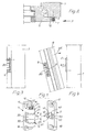
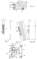
- the base part 2 (FIG. 1) or 3 (FIG. 5) is fastened, in particular screwed, to the fixed frame 1.
- the wing part 4 (FIG. 1) or 5 (FIG. 5) is attached to the wing frame 6 in accordance with the designation of this part.
- the latter and the fixed frame 1 are connected in the exemplary embodiment by a known type of turn-tilt fitting.
- the geometric axis of rotation of the wing coincides with the geometric axis 7 of the braking device.
- the braking device does not hinder the turning of the wing.
- the wing can be moved into the tilted position in a known manner without special measures being required on the braking device, because this has a plug connection 8, 9 or 10, 11, as will be described in more detail below.
- the base part 2 also has a plate-like shape with two horizontal, also countersunk elongated holes 17 and 18, which allow the base part 2 to be aligned with the fixed frame 1 in the horizontal direction, that is to say transversely to the geometric axis 7.
- a bearing member 20 (FIG. 1) or 21 (FIG. 5) is rotatably mounted on the wing part 4 via a rotary bearing 19, the connection being made via a bearing axis 22 or 23.
- a loose bearing axis is used, which is pushed from below through a bore in the bearing eye 14, a coaxial bore of the substantially sleeve-shaped bearing member 20 and finally through the bore in the bearing eye 13.
- a thickened head with a slot or hexagon, which is sunk or at least partially sunk in the bearing eye 14.
- a nut 24 is attached on the top of the bearing eye 13.
- the upper end of the bearing axis 22 is provided with a bolt thread which is screwed into the thread of the nut 24. It is obvious that one can turn the screw trained bearing axis 22 can pull the two bearing eyes 13 and 14 against each other and thereby clamp the bearing member 20 located between them more or less strongly.
- the bearing eyes 13 and 14 do not lie directly on the associated end faces of the bearing member 20, rather there is a brake disk 25 and 26 in between, respectively.
- the material corresponds to the material known for brake pads.
- the bearing axis forms an element of a clamping device 27, which also includes the nut 24.
- the bearing member 21 consists there of a solid part with a bearing pin projecting upwards and downwards, these two bearing pins together forming the bearing axis 23. While the lower bearing pin is only inserted into a hole in the bearing eye 29, the upwardly projecting bearing pin penetrates a hole in the bearing eye 30. It is provided with a bolt thread onto which a clamping nut 31 with an actuating slot or hexagon socket is screwed. In between there are a number of disks. A first brake disk 32 is located directly on the upper side of the bearing eye 30, over which an intermediate disk 33 is located. The latter carries a second brake disk 34 and an end disk 35.
- the intermediate disk 33 has a radially protruding lateral extension 36 which fits into a recess 37 or a longitudinal slot in the stop plate 12 engages and thereby holds the washer 33 rotatably to the stop plate.
- the end plate 35 is held in a manner not shown rotatably to the bearing axis.
- the first and the second brake disks 32 and 34 are non-rotatable with respect to the bearing axis 23. For this purpose it is flattened and the brake discs are adapted to the cross-section of the bearing axis at this point.
- a third brake disk 38 is also installed below the bearing eye 30. It lies on the underside of the bearing eye 30 on the one hand and on the upper end edge of the bearing member 21 on the other.
- the tensioning device 28 accordingly consists of the bearing member 21 with its upper threaded bolt and the nut 31.
- the two bearing eyes 13 and 14 are made in one piece with the stop plate 12, only the bearing eye 30 is molded onto the stop plate 12 of FIG. 5.
- the caustic eye 29, on the other hand is manufactured separately and, after the assembly of all parts, is connected in a suitable manner to the bearing plate 12, for example by riveting. This can be a rivet attachment of the bearing eye 29 push through the plate 12 towards its rearward side, which is permanently deformed after the bearing eye 29 is attached.
- the braking forces are absorbed essentially in the area of the bearing eye 30.
- a radially protruding, preferably rectangular pin 8 is attached or formed on the bearing member 20.
- the bearing member 20, which has a circular outer cross section, is expediently provided with a flattened area 39 at the relevant point. With separate production, this creates a good contact surface. There is also the fact that in this way an extension of the pin 8 to the inside is achieved, which can thereby penetrate deeper into the receptacle 9 of the base part 2.
- the receptacle 9 consists essentially of a recess or an opening 40 in the plate-shaped base part 2 and two parallel strips 41 and 42 projecting beyond the outside thereof. Each strip has a chamfer 43 or 44 on its inside, which when the tilted wing 6 is closed ( Fig. 4) in the direction of arrow 45 the entry of the pin 8 in the receptacle 9 facilitated. Otherwise, the free end of the pin 8 can also be chamfered in a manner not shown.
- the height 46 of the pin 8 is less than the height of the receptacle measured in the same direction. This gives you a sufficient tolerance in the vertical direction during assembly and on the other hand, this reliably ensures that the pin 8 emerges from the receptacle 9, wherein it should be noted that the pin 8 performs an arcuate movement when tilt-opening and tilt-closing according to arrow 45.
- a plug connection is also provided, which consists of a pin 11 and a receptacle 10.
- the pin 11 is fastened to the base part 3 and it has a circular cross section. Its free end is advantageously chamfered.
- the chamfer 11 runs in the longitudinal direction of the bearing axis 23 or the bearing member 21, to which it is attached in the form of an elongated hole recess. With the usual play, the width of the elongated hole corresponds approximately to the diameter of the pin 11. The length is again chosen so that on the one hand there is sufficient installation tolerance in the vertical direction and on the other hand the tilting movement is not hindered.
Landscapes
- Engineering & Computer Science (AREA)
- Mechanical Engineering (AREA)
- Hinges (AREA)
- Wing Frames And Configurations (AREA)
- Pivots And Pivotal Connections (AREA)
- Power-Operated Mechanisms For Wings (AREA)
Claims (13)
- Palier rotatif avec dispositif de freinage pour un battant d'une fenêtre, d'une porte ou similaire, avec une partie de base (2) du palier qui peut être fixée sur un cadre fixe (1) ou au mur et qui est munie d'un organe de palier (20), et avec une partie de battant (4) du palier qui peut être montée sur le battant (6) et qui est assemblée à l'organe de palier de la partie de base par l'intermédiaire d'un axe de palier (22), l'axe de palier traversant un oeil de palier de la partie de battant (4) ainsi que des rondelles de freinage (25,26), et ces rondelles pouvant être sollicitées par une force de freinage à l'aide d'un dispositif de serrage axial (27), caractérisé en ce que la partie de battant présente, à distance axiale de son oeil de palier (13), un second oeil de palier (14), et l'organe de palier (20) de la partie de base (2) s'engage entre les deux yeux de palier (13,14), l'organe de palier (20) étant assemblé à la partie de base (2) par un assemblage par emboîtement (8,9) qui peut être désassemblé approximativement perpendiculairement au plan du battant (6) fermé, et en ce que les deux yeux de palier (13,14) peuvent être tirés élastiquement l'un vers l'autre à l'aide du dispositif de serrage (27), et bloqués en position.
- Palier rotatif avec dispositif de freinage pour un battant d'une fenêtre, d'une porte ou similaire, avec une partie de base (3) du palier qui peut être fixée sur un cadre fixe (1) ou au mur et qui est munie d'un organe de palier (21), et avec une partie de battant (5) du palier qui peut être montée sur le battant (6) et qui est assemblée à l'organe de palier de la partie de base par l'intermédiaire d'un axe de palier (23), l'axe de palier traversant un oeil de palier de la partie de battant (5) ainsi que des rondelles de freinage (32,34,38), et ces rondelles pouvant être sollicitées par une force de freinage à l'aide d'un dispositif de serrage axial (28), caractérisé en ce que l'organe de palier (21) peut être pressé contre l'oeil de palier (30) à l'aide du dispositif de serrage (28), et est assemblé à la partie de base (3) par un assemblage par emboîtement (10,11).
- Palier rotatif avec dispositif de freinage selon la revendication 1 ou 2, caractérisé en ce que le dispositif de serrage (27,28) est constitué par un filetage mâle de l'axe de palier (22) et par un filetage femelle, et en ce qu'au moins une rondelle de freinage (25,26) est intercalée entre l'organe de palier (20) et chaque oeil de palier (13,14), ou en ce que, en présence d'un seul oeil (30), au moins une rondelle de freinage (38) est intercalée au moins entre cet oeil (30) et l'organe de palier (21).
- Palier rotatif avec dispositif de freinage selon la revendication 3, caractérisé en ce qu'une extrémité de l'axe de palier (22) est immobilisée en translation axiale sur un oeil de palier (14) de la partie de battant (4), et le filetage mâle de l'axe de palier (22) s'engage dans un filetage femelle de l'autre oeil de palier (13), ou d'un écrou (24) du dispositif de serrage (27) qui est associé à l'oeil (13) ou fixé sur ce dernier (figure 1).
- Palier rotatif avec dispositif de freinage selon la revendication 3, caractérisé en ce que l'axe de palier (23) est assemblé solidairement en rotation à l'organe de palier (21) ou en est solidaire, et dépasse aux deux extrémités, une extrémité de l'axe portant le filetage mâle sur lequel peut être vissé un écrou (31) du dispositif de serrage (28), et en ce qu'au moins une rondelle de freinage supplémentaire (32,34) est intercalée entre l'écrou (31) et l'oeil de palier associé (30), et l'autre extrémité de l'axe de palier (21) s'engage dans un autre oeil de palier (29) de la partie de battant (5) (figure 5).
- Palier rotatif avec dispositif de freinage selon la revendication 4 ou 5, caractérisé en ce que les deux yeux de palier (13,14; 29,30) sont fixés sur une plaque de butée commune (12) de la partie de battant (4,5), au moins un oeil de palier (13,14,30) étant solidaire de la plaque de butée (12).
- Palier rotatif avec dispositif de freinage selon la revendication 5 ou 6, caractérisé en ce que l'oeil de palier supplémentaire (29), qui est éloigné de l'écrou (31), est réalisé séparément (figure 5).
- Palier rotatif avec dispositif de freinage selon l'une des revendications 5 à 7, caractérisé en ce qu'une rondelle intermédiaire (33), solidaire de la plaque de butée, est intercalée entre deux ou chaque fois entre deux rondelles de freinage (31,34), et en ce qu'une rondelle d'arrêt bloquée en rotation (35) est intercalée entre l'écrou (31) et la rondelle de freinage associée (34).
- Palier rotatif avec dispositif de freinage selon au moins l'une des revendications précédentes, caractérisé en ce que l'assemblage par emboîtement (8,9; 10,11) est constitué d'un tourillon (8,11), et d'un logement (9,10) adapté à la forme de section de ce tourillon.
- Palier rotatif avec dispositif de freinage selon la revendication 9, caractérisé en ce que le tourillon (8) se trouve sur l'organe de palier (20) et présente une section sensiblement rectangulaire, le logement (9) sur la partie de base (2) étant réalisé sous la forme d'une fente longitudinale ou similaire, dont la longueur est supérieure à la hauteur (46) du tourillon (8).
- Palier rotatif avec dispositif de freinage selon la revendication 10, caractérisé en ce que la fente longitudinale (9) est au moins partiellement formée par deux bordures parallèles (41,42) qui dépassent du plan de la partie de base (2) et qui sont notamment chanfreinées vers l'intérieur (43, 44).
- Palier rotatif avec dispositif de freinage selon la revendication 9, caractérisé en ce que le tourillon (11), qui est de préférence de section circulaire, se trouve sur la partie de base (3) et s'engage dans une fente (10) ou similaire de l'organe de palier (21) qui est verticale en position d'utilisation.
- Palier rotatif avec dispositif de freinage selon au moins l'une des revendications précédentes, caractérisé en ce que la partie de base sensiblement en forme de plaque (2,3) présente des trous oblongs de fixation supérieur (17) et inférieur (18), qui sont approximativement horizontaux en position d'utilisation.
Priority Applications (1)
| Application Number | Priority Date | Filing Date | Title |
|---|---|---|---|
| AT87111030T ATE67005T1 (de) | 1986-09-05 | 1987-07-30 | Bremsvorrichtung fuer einen fluegel eines fensters, einer tuer od. dgl. |
Applications Claiming Priority (2)
| Application Number | Priority Date | Filing Date | Title |
|---|---|---|---|
| DE8623877U | 1986-09-05 | ||
| DE8623877U DE8623877U1 (de) | 1986-09-05 | 1986-09-05 | Bremsvorrichtung für einen Flügel eines Fensters, einer Tür od.dgl. |
Publications (3)
| Publication Number | Publication Date |
|---|---|
| EP0258639A2 EP0258639A2 (fr) | 1988-03-09 |
| EP0258639A3 EP0258639A3 (en) | 1988-07-20 |
| EP0258639B1 true EP0258639B1 (fr) | 1991-09-04 |
Family
ID=6798065
Family Applications (1)
| Application Number | Title | Priority Date | Filing Date |
|---|---|---|---|
| EP87111030A Expired - Lifetime EP0258639B1 (fr) | 1986-09-05 | 1987-07-30 | Palier rotatif avec dispositif de freinage pour un panneau de fenêtre, porte ou similaire |
Country Status (3)
| Country | Link |
|---|---|
| EP (1) | EP0258639B1 (fr) |
| AT (1) | ATE67005T1 (fr) |
| DE (2) | DE8623877U1 (fr) |
Families Citing this family (2)
| Publication number | Priority date | Publication date | Assignee | Title |
|---|---|---|---|---|
| FR2675191B1 (fr) * | 1991-04-09 | 1995-10-13 | Technal Sa | Dispositif a paumelle debrayable. |
| US5652694A (en) * | 1996-02-01 | 1997-07-29 | Canon Business Machines, Inc. | Friction hinge including compressed friction washer |
Family Cites Families (4)
| Publication number | Priority date | Publication date | Assignee | Title |
|---|---|---|---|---|
| FR851655A (fr) * | 1938-09-22 | 1940-01-12 | Paumelle | |
| US3406483A (en) * | 1967-03-16 | 1968-10-22 | Ford Motor Co | Combination hinge-latch device |
| FR2562136B1 (fr) * | 1984-03-29 | 1986-06-27 | Ferco Int Usine Ferrures | Dispositif d'applique intermediaire entre deux articulations |
| GB2166796B (en) * | 1984-11-08 | 1987-09-09 | Southco | Adjustable friction hinge |
-
1986
- 1986-09-05 DE DE8623877U patent/DE8623877U1/de not_active Expired
-
1987
- 1987-07-30 EP EP87111030A patent/EP0258639B1/fr not_active Expired - Lifetime
- 1987-07-30 AT AT87111030T patent/ATE67005T1/de not_active IP Right Cessation
- 1987-07-30 DE DE8787111030T patent/DE3772673D1/de not_active Expired - Lifetime
Also Published As
| Publication number | Publication date |
|---|---|
| DE3772673D1 (de) | 1991-10-10 |
| DE8623877U1 (de) | 1986-10-23 |
| ATE67005T1 (de) | 1991-09-15 |
| EP0258639A3 (en) | 1988-07-20 |
| EP0258639A2 (fr) | 1988-03-09 |
Similar Documents
| Publication | Publication Date | Title |
|---|---|---|
| EP0259618B1 (fr) | Penture de porte et fenêtre, réglable pendant et après le montage | |
| EP0467075B1 (fr) | Ferrure d'articulation pour portes, fenêtres et similaires, et élément de positionnement pour l'élément de guidage d'une telle ferrure | |
| EP1235967B1 (fr) | Bande pour portes, fenetres et similaires | |
| DE3240452A1 (de) | Treibstangenbeschlag fuer fenster, tueren o. dgl. | |
| EP1437467B1 (fr) | Charnière pour portes ou fenêtres | |
| DE19521539A1 (de) | Drehlager, insbesondere Scherenlager eines Drehbeschlags oder Dreh-Kippbeschlags für Fenster, Türen oder dergleichen | |
| EP0754827B1 (fr) | Dispositif pour la fixation amovible et axialement non coulissante d'une poignée sur un élément de palier, notamment pour une poignée de porte ou fenêtre | |
| EP0294630A2 (fr) | Fermeture pour fenêtres, portes, etc. | |
| EP0340456B1 (fr) | Palier de compas pour fenêtre oscillo-battante | |
| EP1863990B1 (fr) | Mecanisme de commande de bielle | |
| EP0258639B1 (fr) | Palier rotatif avec dispositif de freinage pour un panneau de fenêtre, porte ou similaire | |
| EP2317047B1 (fr) | Agencement de ferrure | |
| WO2007014604A1 (fr) | Systeme a profile et a bande | |
| WO2007087945A1 (fr) | Ensemble charnière permettant une liaison par l'intermédiaire d'une articulation à charnière | |
| DE19526016B4 (de) | Exzenterverstelleinrichtung für einen Beschlag für Fenster, Türen oder dergleichen | |
| EP1563152B1 (fr) | Charniere | |
| EP2304148A1 (fr) | Système de bande | |
| DE4323939C2 (de) | Gelenkvorrichtung, insbesondere für Drehkipptür oder -fenster | |
| EP2385200B1 (fr) | Elément de ferrure pour la fixation dans une rainure de ferrure en forme de C | |
| EP0340455B2 (fr) | Pivot pour la connexion de deux battants d'une fenêtre, d'une porte ou similaire | |
| EP2514892B1 (fr) | Système de fixation d'une partie de ferrure | |
| EP3667010B1 (fr) | Dispositif de butée pour un joint de porte automatique, en particulier pour une porte pivotante ou battante, agencement d'un joint de porte automatique et d'un dispositif de butée | |
| EP1688570B1 (fr) | Charnière pour portes, fenêtres ou similaire | |
| WO2007028490A1 (fr) | Charniere pour portes, fenetres ou elements similaires | |
| EP3101207B1 (fr) | Dispositif de porte coulissante |
Legal Events
| Date | Code | Title | Description |
|---|---|---|---|
| PUAI | Public reference made under article 153(3) epc to a published international application that has entered the european phase |
Free format text: ORIGINAL CODE: 0009012 |
|
| AK | Designated contracting states |
Kind code of ref document: A2 Designated state(s): AT CH DE FR GB LI |
|
| PUAL | Search report despatched |
Free format text: ORIGINAL CODE: 0009013 |
|
| AK | Designated contracting states |
Kind code of ref document: A3 Designated state(s): AT CH DE FR GB LI |
|
| 17P | Request for examination filed |
Effective date: 19881003 |
|
| 17Q | First examination report despatched |
Effective date: 19890814 |
|
| GRAA | (expected) grant |
Free format text: ORIGINAL CODE: 0009210 |
|
| AK | Designated contracting states |
Kind code of ref document: B1 Designated state(s): AT CH DE FR GB LI |
|
| REF | Corresponds to: |
Ref document number: 67005 Country of ref document: AT Date of ref document: 19910915 Kind code of ref document: T |
|
| REF | Corresponds to: |
Ref document number: 3772673 Country of ref document: DE Date of ref document: 19911010 |
|
| ET | Fr: translation filed | ||
| GBT | Gb: translation of ep patent filed (gb section 77(6)(a)/1977) | ||
| PGFP | Annual fee paid to national office [announced via postgrant information from national office to epo] |
Ref country code: CH Payment date: 19920611 Year of fee payment: 6 |
|
| PGFP | Annual fee paid to national office [announced via postgrant information from national office to epo] |
Ref country code: AT Payment date: 19920616 Year of fee payment: 6 |
|
| PLBE | No opposition filed within time limit |
Free format text: ORIGINAL CODE: 0009261 |
|
| STAA | Information on the status of an ep patent application or granted ep patent |
Free format text: STATUS: NO OPPOSITION FILED WITHIN TIME LIMIT |
|
| PG25 | Lapsed in a contracting state [announced via postgrant information from national office to epo] |
Ref country code: GB Effective date: 19920730 |
|
| 26N | No opposition filed | ||
| GBPC | Gb: european patent ceased through non-payment of renewal fee |
Effective date: 19920730 |
|
| PG25 | Lapsed in a contracting state [announced via postgrant information from national office to epo] |
Ref country code: AT Effective date: 19930730 |
|
| PG25 | Lapsed in a contracting state [announced via postgrant information from national office to epo] |
Ref country code: LI Effective date: 19930731 Ref country code: CH Effective date: 19930731 |
|
| REG | Reference to a national code |
Ref country code: CH Ref legal event code: PL |
|
| PGFP | Annual fee paid to national office [announced via postgrant information from national office to epo] |
Ref country code: FR Payment date: 20010709 Year of fee payment: 15 |
|
| PGFP | Annual fee paid to national office [announced via postgrant information from national office to epo] |
Ref country code: DE Payment date: 20010713 Year of fee payment: 15 |
|
| PG25 | Lapsed in a contracting state [announced via postgrant information from national office to epo] |
Ref country code: DE Free format text: LAPSE BECAUSE OF NON-PAYMENT OF DUE FEES Effective date: 20030201 |
|
| PG25 | Lapsed in a contracting state [announced via postgrant information from national office to epo] |
Ref country code: FR Free format text: LAPSE BECAUSE OF NON-PAYMENT OF DUE FEES Effective date: 20030331 |
|
| REG | Reference to a national code |
Ref country code: FR Ref legal event code: ST |