EP0258549A2 - Stapelbarer Flaschenkasten - Google Patents
Stapelbarer Flaschenkasten Download PDFInfo
- Publication number
- EP0258549A2 EP0258549A2 EP87108402A EP87108402A EP0258549A2 EP 0258549 A2 EP0258549 A2 EP 0258549A2 EP 87108402 A EP87108402 A EP 87108402A EP 87108402 A EP87108402 A EP 87108402A EP 0258549 A2 EP0258549 A2 EP 0258549A2
- Authority
- EP
- European Patent Office
- Prior art keywords
- handle
- box according
- box
- compartments
- compartment
- Prior art date
- Legal status (The legal status is an assumption and is not a legal conclusion. Google has not performed a legal analysis and makes no representation as to the accuracy of the status listed.)
- Granted
Links
- 230000002349 favourable effect Effects 0.000 description 4
- 238000007654 immersion Methods 0.000 description 3
- 230000015572 biosynthetic process Effects 0.000 description 2
- 238000007493 shaping process Methods 0.000 description 2
- 208000027418 Wounds and injury Diseases 0.000 description 1
- 230000006978 adaptation Effects 0.000 description 1
- 238000004873 anchoring Methods 0.000 description 1
- 239000007799 cork Substances 0.000 description 1
- 230000006378 damage Effects 0.000 description 1
- 238000011161 development Methods 0.000 description 1
- 230000018109 developmental process Effects 0.000 description 1
- 208000014674 injury Diseases 0.000 description 1
- 230000003993 interaction Effects 0.000 description 1
Images


Classifications
-
- B—PERFORMING OPERATIONS; TRANSPORTING
- B65—CONVEYING; PACKING; STORING; HANDLING THIN OR FILAMENTARY MATERIAL
- B65D—CONTAINERS FOR STORAGE OR TRANSPORT OF ARTICLES OR MATERIALS, e.g. BAGS, BARRELS, BOTTLES, BOXES, CANS, CARTONS, CRATES, DRUMS, JARS, TANKS, HOPPERS, FORWARDING CONTAINERS; ACCESSORIES, CLOSURES, OR FITTINGS THEREFOR; PACKAGING ELEMENTS; PACKAGES
- B65D1/00—Rigid or semi-rigid containers having bodies formed in one piece, e.g. by casting metallic material, by moulding plastics, by blowing vitreous material, by throwing ceramic material, by moulding pulped fibrous material or by deep-drawing operations performed on sheet material
- B65D1/22—Boxes or like containers with side walls of substantial depth for enclosing contents
- B65D1/24—Boxes or like containers with side walls of substantial depth for enclosing contents with moulded compartments or partitions
- B65D1/243—Crates for bottles or like containers
-
- B—PERFORMING OPERATIONS; TRANSPORTING
- B65—CONVEYING; PACKING; STORING; HANDLING THIN OR FILAMENTARY MATERIAL
- B65D—CONTAINERS FOR STORAGE OR TRANSPORT OF ARTICLES OR MATERIALS, e.g. BAGS, BARRELS, BOTTLES, BOXES, CANS, CARTONS, CRATES, DRUMS, JARS, TANKS, HOPPERS, FORWARDING CONTAINERS; ACCESSORIES, CLOSURES, OR FITTINGS THEREFOR; PACKAGING ELEMENTS; PACKAGES
- B65D2501/00—Containers having bodies formed in one piece
- B65D2501/24—Boxes or like containers with moulded compartments or partitions
- B65D2501/24006—Details relating to bottle crates
- B65D2501/24012—Materials
- B65D2501/24019—Mainly plastics
-
- B—PERFORMING OPERATIONS; TRANSPORTING
- B65—CONVEYING; PACKING; STORING; HANDLING THIN OR FILAMENTARY MATERIAL
- B65D—CONTAINERS FOR STORAGE OR TRANSPORT OF ARTICLES OR MATERIALS, e.g. BAGS, BARRELS, BOTTLES, BOXES, CANS, CARTONS, CRATES, DRUMS, JARS, TANKS, HOPPERS, FORWARDING CONTAINERS; ACCESSORIES, CLOSURES, OR FITTINGS THEREFOR; PACKAGING ELEMENTS; PACKAGES
- B65D2501/00—Containers having bodies formed in one piece
- B65D2501/24—Boxes or like containers with moulded compartments or partitions
- B65D2501/24006—Details relating to bottle crates
- B65D2501/2405—Construction
- B65D2501/24063—Construction of the walls
- B65D2501/24089—Height of the side walls
- B65D2501/24095—Height of the side walls corresponding to the full height of the bottles
-
- B—PERFORMING OPERATIONS; TRANSPORTING
- B65—CONVEYING; PACKING; STORING; HANDLING THIN OR FILAMENTARY MATERIAL
- B65D—CONTAINERS FOR STORAGE OR TRANSPORT OF ARTICLES OR MATERIALS, e.g. BAGS, BARRELS, BOTTLES, BOXES, CANS, CARTONS, CRATES, DRUMS, JARS, TANKS, HOPPERS, FORWARDING CONTAINERS; ACCESSORIES, CLOSURES, OR FITTINGS THEREFOR; PACKAGING ELEMENTS; PACKAGES
- B65D2501/00—Containers having bodies formed in one piece
- B65D2501/24—Boxes or like containers with moulded compartments or partitions
- B65D2501/24006—Details relating to bottle crates
- B65D2501/2405—Construction
- B65D2501/24121—Construction of the bottom
- B65D2501/24133—Grid, mesh
-
- B—PERFORMING OPERATIONS; TRANSPORTING
- B65—CONVEYING; PACKING; STORING; HANDLING THIN OR FILAMENTARY MATERIAL
- B65D—CONTAINERS FOR STORAGE OR TRANSPORT OF ARTICLES OR MATERIALS, e.g. BAGS, BARRELS, BOTTLES, BOXES, CANS, CARTONS, CRATES, DRUMS, JARS, TANKS, HOPPERS, FORWARDING CONTAINERS; ACCESSORIES, CLOSURES, OR FITTINGS THEREFOR; PACKAGING ELEMENTS; PACKAGES
- B65D2501/00—Containers having bodies formed in one piece
- B65D2501/24—Boxes or like containers with moulded compartments or partitions
- B65D2501/24006—Details relating to bottle crates
- B65D2501/2405—Construction
- B65D2501/24146—Connection between walls or of walls with bottom
- B65D2501/24152—Integral
-
- B—PERFORMING OPERATIONS; TRANSPORTING
- B65—CONVEYING; PACKING; STORING; HANDLING THIN OR FILAMENTARY MATERIAL
- B65D—CONTAINERS FOR STORAGE OR TRANSPORT OF ARTICLES OR MATERIALS, e.g. BAGS, BARRELS, BOTTLES, BOXES, CANS, CARTONS, CRATES, DRUMS, JARS, TANKS, HOPPERS, FORWARDING CONTAINERS; ACCESSORIES, CLOSURES, OR FITTINGS THEREFOR; PACKAGING ELEMENTS; PACKAGES
- B65D2501/00—Containers having bodies formed in one piece
- B65D2501/24—Boxes or like containers with moulded compartments or partitions
- B65D2501/24006—Details relating to bottle crates
- B65D2501/24197—Arrangements for locating the bottles
- B65D2501/24203—Construction of locating arrangements
- B65D2501/2421—Partitions
- B65D2501/24216—Partitions forming square or rectangular cells
-
- B—PERFORMING OPERATIONS; TRANSPORTING
- B65—CONVEYING; PACKING; STORING; HANDLING THIN OR FILAMENTARY MATERIAL
- B65D—CONTAINERS FOR STORAGE OR TRANSPORT OF ARTICLES OR MATERIALS, e.g. BAGS, BARRELS, BOTTLES, BOXES, CANS, CARTONS, CRATES, DRUMS, JARS, TANKS, HOPPERS, FORWARDING CONTAINERS; ACCESSORIES, CLOSURES, OR FITTINGS THEREFOR; PACKAGING ELEMENTS; PACKAGES
- B65D2501/00—Containers having bodies formed in one piece
- B65D2501/24—Boxes or like containers with moulded compartments or partitions
- B65D2501/24006—Details relating to bottle crates
- B65D2501/24197—Arrangements for locating the bottles
- B65D2501/24203—Construction of locating arrangements
- B65D2501/24261—Ribs on the side walls
-
- B—PERFORMING OPERATIONS; TRANSPORTING
- B65—CONVEYING; PACKING; STORING; HANDLING THIN OR FILAMENTARY MATERIAL
- B65D—CONTAINERS FOR STORAGE OR TRANSPORT OF ARTICLES OR MATERIALS, e.g. BAGS, BARRELS, BOTTLES, BOXES, CANS, CARTONS, CRATES, DRUMS, JARS, TANKS, HOPPERS, FORWARDING CONTAINERS; ACCESSORIES, CLOSURES, OR FITTINGS THEREFOR; PACKAGING ELEMENTS; PACKAGES
- B65D2501/00—Containers having bodies formed in one piece
- B65D2501/24—Boxes or like containers with moulded compartments or partitions
- B65D2501/24006—Details relating to bottle crates
- B65D2501/24197—Arrangements for locating the bottles
- B65D2501/24343—Position pattern
- B65D2501/2435—Columns and rows
-
- B—PERFORMING OPERATIONS; TRANSPORTING
- B65—CONVEYING; PACKING; STORING; HANDLING THIN OR FILAMENTARY MATERIAL
- B65D—CONTAINERS FOR STORAGE OR TRANSPORT OF ARTICLES OR MATERIALS, e.g. BAGS, BARRELS, BOTTLES, BOXES, CANS, CARTONS, CRATES, DRUMS, JARS, TANKS, HOPPERS, FORWARDING CONTAINERS; ACCESSORIES, CLOSURES, OR FITTINGS THEREFOR; PACKAGING ELEMENTS; PACKAGES
- B65D2501/00—Containers having bodies formed in one piece
- B65D2501/24—Boxes or like containers with moulded compartments or partitions
- B65D2501/24006—Details relating to bottle crates
- B65D2501/24197—Arrangements for locating the bottles
- B65D2501/24343—Position pattern
- B65D2501/24356—Staggered
-
- B—PERFORMING OPERATIONS; TRANSPORTING
- B65—CONVEYING; PACKING; STORING; HANDLING THIN OR FILAMENTARY MATERIAL
- B65D—CONTAINERS FOR STORAGE OR TRANSPORT OF ARTICLES OR MATERIALS, e.g. BAGS, BARRELS, BOTTLES, BOXES, CANS, CARTONS, CRATES, DRUMS, JARS, TANKS, HOPPERS, FORWARDING CONTAINERS; ACCESSORIES, CLOSURES, OR FITTINGS THEREFOR; PACKAGING ELEMENTS; PACKAGES
- B65D2501/00—Containers having bodies formed in one piece
- B65D2501/24—Boxes or like containers with moulded compartments or partitions
- B65D2501/24006—Details relating to bottle crates
- B65D2501/24363—Handles
- B65D2501/24509—Integral handles
- B65D2501/24528—Integral handles centrally located in open container
-
- B—PERFORMING OPERATIONS; TRANSPORTING
- B65—CONVEYING; PACKING; STORING; HANDLING THIN OR FILAMENTARY MATERIAL
- B65D—CONTAINERS FOR STORAGE OR TRANSPORT OF ARTICLES OR MATERIALS, e.g. BAGS, BARRELS, BOTTLES, BOXES, CANS, CARTONS, CRATES, DRUMS, JARS, TANKS, HOPPERS, FORWARDING CONTAINERS; ACCESSORIES, CLOSURES, OR FITTINGS THEREFOR; PACKAGING ELEMENTS; PACKAGES
- B65D2501/00—Containers having bodies formed in one piece
- B65D2501/24—Boxes or like containers with moulded compartments or partitions
- B65D2501/24006—Details relating to bottle crates
- B65D2501/24363—Handles
- B65D2501/24541—Hand holes
-
- B—PERFORMING OPERATIONS; TRANSPORTING
- B65—CONVEYING; PACKING; STORING; HANDLING THIN OR FILAMENTARY MATERIAL
- B65D—CONTAINERS FOR STORAGE OR TRANSPORT OF ARTICLES OR MATERIALS, e.g. BAGS, BARRELS, BOTTLES, BOXES, CANS, CARTONS, CRATES, DRUMS, JARS, TANKS, HOPPERS, FORWARDING CONTAINERS; ACCESSORIES, CLOSURES, OR FITTINGS THEREFOR; PACKAGING ELEMENTS; PACKAGES
- B65D2501/00—Containers having bodies formed in one piece
- B65D2501/24—Boxes or like containers with moulded compartments or partitions
- B65D2501/24006—Details relating to bottle crates
- B65D2501/24554—Stacking means
- B65D2501/24585—Stacking means for stacking or joining the crates together one upon the other, in the upright or upside-down position
- B65D2501/24605—Crates with stacking feet or corner elements
Definitions
- the invention relates to a stackable bottle crate according to the preamble of claim 1.
- Conventional bottle crates are made of plastic and have a compartment division for accommodating the bottles to be transported between the side walls encompassing the crate interior. These boxes usually have external dimensions of 400 x 300 mm and accommodate a total of twenty bottles. The bottle crate is transported via the handle openings provided in the side walls. The dimensions of such a box are comparatively bulky and can only be transported with difficulty through the handle openings in the side walls. The stacking is only vertical, an offset stacking is not possible. Overall, such boxes are unfavorably designed for the purpose of transport, because they are too bulky and too heavy and because gripping the box through the recessed handle openings is cumbersome and can only be done by strong people.
- the object of the invention is therefore to create a bottle crate which ensures consumer-friendly transport and at the same time permits stable and universal stacking.
- the invention is characterized by a targeted interaction of the arrangement of a center handle and the formation of a box bottom, which allows a design of the center handle that is favorable for gripping and transporting the box to be obtained and nevertheless ensures stable stacking.
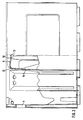
- this immersion of the central handle enables the handle bar to be pulled up in order to provide sufficient space below the handle bar for gripping the box.
- the recesses for the center handle are arranged in the bottom of the box so that they match or are aligned with the possible positions of the handle in the various stacking positions
- the advantage according to claim 1 also results in different stacking positions of the boxes.
- the training according to claim 12 is advantageous because a box module from 400 x 200 mm also permits an offset stacking of the boxes and in particular also stacking in connection with boxes of the so-called Euro standard, i.e. a module of 400 mm x 300 mm.
- the stable stacking is further favored by the fact that the bottom of the recess is formed as a contact surface for the handle. As a result, the handle is also used for support.
- the depth of the recess can be added to the grip area.
- the grip strip it is expedient for the grip strip to be curved in a substantially shell-like manner in longitudinal section, resulting in an ergonomically favorable grip.
- This advantage is only possible in that a corresponding pulling up of the handle is made possible due to the immersion of the handle in the recess.
- the grip behavior is further favored by the fact that the grip strip is essentially U-shaped in cross-section transversely to the longitudinal direction of the handle, the U-web being formed by a rounding.
- the openings in the bottom grille are designed in particular also in the recesses in such a way that the crown cork or the bottle neck cannot pass through.
- the stability of the box is further enhanced by the fact that the side walls are double-walled. In particular, this enables the boxes to be stacked horizontally.
- knobs, notches or webs on the outer surface of the web walls is favorable, as a result of which the wear on the side walls is reduced.
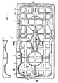
- the compartment division has a total of three compartment rows, of which the two outer compartment rows each limit four compartments 2 for holding bottles, whereas two compartments are present in the inner compartment row.
- the inner compartment row is aligned with a center handle 5, which is shown in detail in FIGS. 2 and 3.
- the bottle crate according to FIGS. 1 to 3 holds ten bottles, namely four each in the outer compartment rows and two in the inner compartment row, the two bottles in the inner compartment row being arranged offset to the adjacent bottles of the outer compartment row.
- the bottle crate 1 comprises four side walls 4, which are preferably double-walled. Especially in the narrower side walls are only in the drawings schematically shown handle openings 3 are provided, which can optionally be provided in addition to the center handle 5.
- the individual compartments 2, as far as the subjects of the outer rows of compartments are concerned, are delimited by the side walls 4 and compartment walls 6 formed in the interior of the box.
- the two compartments of the inner compartment row are limited solely by compartment walls 6, which form a column 7 with an octagonal floor plan.
- FIGS. 1 to 3 enables the bottles to be accommodated in the compartments by means of three-point storage. For example, the bottle 8 shown at the top left in FIG.
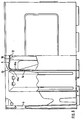
- the box bottom according to FIG. 1 has a series of recesses 11, as can be seen from the right-hand illustration in FIG. 1.
- the box is characterized by a length and width module of 400 x 200 mm, in contrast to the Euro standard with 300 x 400 mm, there is a large number of different stacking options also in connection with boxes of the Euronorm.
- the recesses 11 are designed so that even with a staggered stacking in the direction of length or width, the center handle or a recess comes to lie below or above a recess 11 or the center handle 5 and thus ensures stacking is.
- the middle handle 5 immersed in the corresponding recess 11 comes into contact with the bottom surface of the recess 11, so that there is an additional effective support of the load when stacking columns, that is to say vertically stacking the bottle crates. In this respect, there is an additional support surface due to the design of the recess 11 and the central handle 5.
- the upper handle bar 12 is curved downward in the manner of a shell, the lowest position being in the central region of the handle bar 12.
- the grip strip 12 Towards the two ends of the grip strip 12, it is pulled upwards and merges into a vertical support strut 14 on both sides via a curve 13.
- the grip strip 12 has the shape of a large U in a section transverse to the section according to FIG. 2, the two U legs 15 being connected to one another via a rounding 16, so that the U web is rounded is trained.
- the Curvature of the handle bar 12 in the longitudinal direction of the central handle 5 and the rounding on the underside of the handle bar 12 results overall in a handle bar 12 which is easy to grasp, in particular the curvature in the longitudinal direction of the central handle being possible due to the free space which results from the immersion of the central handle 5 in the recesses 11 of the box bottom is made possible.
- Fig. 1 shows that the box floor is like a floor grid, that is, with a number of openings 17a, 17b and 17c ..., these floor openings are also provided in the region of the recesses 11. These bottom openings 17a ... are dimensioned so that the bottles of a lower crate layer cannot dip through the crate bottom of the top layer.
- knobs, notches and webs in the manner of ribs which are formed or molded on the outer surface of the side walls 4 and provide stiffening of the side walls and wear protection when the box is arranged horizontally when the box is on one of the side walls is arranged standing.
- the webs extend in particular essentially over the entire depth or height of the bottle crate.
- the double-wall structure of the side wall 4 can be closed on the inner surface, as can be seen from a comparison with the side wall at the top left in FIG. 4.
- the closed structure of the side wall 4 has the advantage that dirt cannot build up on the side wall or in the region of openings in the side wall.
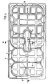
- FIGS. 4 to 6 differs from the embodiment according to FIGS. 1 to 3 in that the compartment division consists of two parallel rows of compartments, each with five compartments.
- the structure of the center handle is similar to the embodiment according to FIGS. 1 to 3, so that an additional explanation appears to be unnecessary.
- recesses 11 are formed at those points at which the center handle 5 can come to rest in different stacking positions in order to ensure that the center handle 5 is immersed in the bottom of the box and thus ensures vertical stacking.
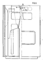
- the center handle has both in the region of the handle bar 12 and in the region of the essentially vertical ones Handle struts 14 in cross section on an open profile, which is essentially U-shaped or shell-shaped in the illustrated embodiment.
- the open profile of the center handle has, in particular in the central section, a region 16a set back from the profile ends 15a and 15b. In the exemplary embodiment shown, this recessed area is equal to the U-web between the two U-legs 15.
- This design of the center handle has the advantage that the burr that arises during the shaping of the box as a result of the separating edges of the tool can be shifted into this area, so that when the box is gripped the hand does not come into contact with the possibly sharp-edged ridge and thus risk of injury excluded are. Furthermore, an increase in the stiffness of the handle is achieved due to the curved profile of the center handle. A special adaptation of the handle to the load handling function is achieved when stacking several boxes on top of each other. The stiffening of the handle as a result of the profile of the central handle also brings about a stable connection of the handle to the box, which in turn is advantageous when carrying the box.
Landscapes
- Engineering & Computer Science (AREA)
- Ceramic Engineering (AREA)
- Mechanical Engineering (AREA)
- Stackable Containers (AREA)
- Details Of Rigid Or Semi-Rigid Containers (AREA)
- Containers Having Bodies Formed In One Piece (AREA)
- Basic Packing Technique (AREA)
- Steroid Compounds (AREA)
- Auxiliary Devices For And Details Of Packaging Control (AREA)
Abstract
Description
- Die Erfindung betrifft einen stapelbaren Flaschenkasten gemäß dem Oberbegriff des Patentanspruches 1.
- Herkömmliche Flaschenkästen sind aus Kunststoff hergestellt und weisen zwischen den das Kasteninnere umfaßenden Seitenwänden eine Facheinteilung für die Aufnahme der zu transportierenden Flaschen auf. Oblicherweise besitzen diese Kästen Außenabmessungen von 400 x 300 mm und nehmen insgesamt zwanzig Flaschen auf. Der Transport des Flaschenkastens erfolgt über in den Seitenwänden vorgesehenen Grifföffnungen. Ein derartiger Kasten ist von seinen Abmessungen her vergleichsweise sperrig und über die Grifföffnungen in den Seitenwänden nur umständlich zu transportieren. Die Stapelung erfolgt ausschließlich vertikal, eine versetzte Stapelung ist nicht möglich. Insgesamt sind derartige Kästen für den Zweck des Transportes ungünstig ausgelegt, weil sie zu sperrig und zu schwer sind und weil das Ergreifen des Kastens über die in den Seitenwänden eingelassenen Grifföffnungen umständlich ist sowie nur von kräftigen Personen vorgenommen werden kann.
- Es besteht demnach ein Bedürfnis nach Flaschenkästen, die eine vielseitige stabile Stapelung zulassen und ein unter ökonomischen Gesichtspunkten günstiges Tragverhalten ergeben.
- Aufgabe der Erfindung ist es somit, einen Flaschenkasten zu schaffen, der einen konsumentenfreundlichen Transport gewährleistet und gleichwohl eine stabile und universelle Stapelung erlaubt.
- Diese Aufgabe wird erfindungsgemäß durch die im kennzeichnenden Teil des Patentanspruches 1 enthaltenen Merkmale gelöst.
- Die Erfindung zeichnet sich durch ein gezieltes Zusammenwirken der Anordnung eines Mittelhandgriffes und der Ausbildung eines Kastenbodens aus, die es erlaubt, eine für das Ergreifen und Transportieren des Kastens günstige Gestaltung des Mittelhandgriffes zu erhalten und gleichwohl eine stabile Stapelung zu gewährleisten. Dadurch, daß der Mittelhandgriff in eine Ausnehmung im Kastenboden eines darüber angeordneten Kastens eintaucht, ergibt sich gewissermaßen eine Verankerung der Kästen in Stapellage, die den Stapel insgesamt seitlich stabilisiert und auch eine Zentrierung beim Stapeln ergibt. Gleichzeitig ermöglicht dieses Eintauchen des Mittelhandgriffs ein Hochziehen der Griffleiste, um unterhalb der Griffleiste einen ausreichenden Freiraum für das Ergreifen des Kastens zu ergeben.
- Dadurch, daß entsprechend Anspruch 2 die Ausnehmungen für den Mittelhandgriff so im Kastenboden angeordnet sind, daß sie mit den möglichen Stellungen des Handgriffes in den verschiedenen Stapellagen übereinstimmen bzw. ausgerichtet sind, ergibt sich der Vorteil nach Anspruch 1 auch in unterschiedlichen Stapelstellungen der Kästen. In diesem Zusammenhang ist die Ausbildung nach Anspruch 12 von Vorteil, da ein Kastenmodul von 400 x 200 mm auch eine versetzte Stapelung der Kästen zuläßt und insbesondere auch eine Stapelung in Verbindung mit Kästen der sogenannten Euro-Norm, also einem Modul von 400 mm x 300 mm.
- Begünstigt wird die stabile Stapelung noch dadurch, daß der Boden der Ausnehmung als Aufstandsfläche für den Handgriff gebildet ist. Dadurch wird der Handgriff zusätzlich zur Stützung herangezogen.
- Dadurch, daß die Griffleiste des Mittelhandgriffes im wesentlichen um das Maß der Tiefe der Ausnehmung hochgezogen ist, kann die Tiefe der Ausnehmung dem Griffbereich zugeschlagen werden.
- In diesem Zusammenhang ist es zweckmäßig, daß die Griffleiste im Längsschnitt im wesentlichen schalenförmig nach unten gewölbt ausgebildet ist, wodurch sich ein ergonomisch günstiger Griff ergibt. Dieser Vorteil ist erst dadurch möglich, daß infolge des Eintauchens des Griffs in die Ausnehmung ein entsprechendes Hochziehen des Handgriffes ermöglicht ist.
- Das Griffverhalten wird noch dadurch begünstigt, daß die Griffleiste im Querschnitt quer zur Längsrichtung des Handgriffes im wesentlichen U-förmig ausgebildet ist, wobei der U-Steg durch eine Rundung gebildet ist.
- Um ein Durchstoßen bzw. Durchtauchen von Flaschen der unteren Lage durch den darüberliegenden Kastenboden der oberen Lage zu verhindern, sind die Öffnungen des Bodengitters insbesondere auch in den Ausnehmungen so ausgebildet, daß der Kronenkorken oder der Flaschenhals nicht hindurchtreten kann.
- Die Stabilität des Kastens wird noch dadurch begünstigt, daß die Seitenwände doppelwandig aufgebaut sind. Dies ermöglicht insbesondere ein waagerechtes Stapeln der Kästen.
- Günstig bei einer waagerechten Stapelung ist die Anordnung bzw. Ausbildung von Noppen, Rasten oder Stegen an der Außenfläche der Stegwände, wodurch der Verschleiß der Seitenwände gemindert wird.
- Zweckmäßige Weiterbildungen der Erfindung ergeben sich aus den weiteren Unteransprüchen.
- Nachfolgend werden Ausführungsbeispiele der Erfindung anhand der Zeichnung beschrieben. Darin zeigen
- Fig. 1 eine Bodenansicht einer Ausführungsform eines Flaschenkastens,
- Fig. 2 eine Schnittansicht längs Linie C-C der Fig. 1,
- Fig. 3 einen Schnitt längs Linie B-B in der Fig. 1,
- Fig. 4 eine Bodenansicht einer weiteren Ausführungsform eines Flaschenkastens,
- Fig. 5 einen Schnitt längs Linie C-C in Fig. 3,
- Fig. 6 eine Schnittansicht längs Linie B-B von Fig. 2,
- Fig. 7 eine Draufsicht auf eine weitere Ausführungsform eines Flaschenkastens sowie
- Fig. 8 eine Schnittansicht des in Fig. 7 dargestellten Kastens zur Darstellung des Mittelhandgriffs.
- Bei der in den Fig. 1 bis 3 dargestellten Ausführungsform eines Flaschenkastens 1 weist die Facheinteilung insgesamt drei Fachreihen auf, von denen die beiden äußeren Fachreihen jeweils vier Fächer 2 zur Aufnahme von Flaschen begrenzen, wohingegen in der inneren Fachreihe zwei Fächer vorhanden sind. Die innere Fachreihe fluchtet mit einem Mittelhandgriff 5, der in seinen Einzelheiten in den Fig. 2 und 3 dargestellt ist. Insgesamt nimmt der Flaschenkasten nach den Fig. 1 bis 3 zehn Flaschen auf, nämlich jeweils vier in den äußeren Fachreihen und zwei in der inneren Fachreihe, wobei die beiden Flaschen in der inneren Fachreihe versetzt zu den benachbarten Flaschen der äußeren Fachreihe angeordnet sind.
- Der Flaschenkasten 1 umfaßt vier Seitenwände 4, die bevorzugt doppelwandig ausgebildet sind. Insbesondere in den schmäleren Seitenwänden sind in den Zeichnungen nur schematisch dargestellte Grifföffnungen 3 vorgesehen, die wahlweise zusätzlich zum Mittelhandgriff 5 vorgesehen sein können. Die einzelnen Fächer 2 sind, soweit die Fächer der äußeren Fachreihen betroffen sind, durch die Seitenwände 4 und im Inneren des Kastens ausgebildete Fachwände 6 begrenzt. Die beiden Fächer der inneren Fachreihe sind alleine durch Fachwände 6 begrenzt, welche eine Säule 7 mit oktagonalem Grundriß bilden. Die Ausführungsform nach den Fig. 1 bis 3 ermöglicht die Aufnahme der Flaschen in den Fächern im Wege einer Dreipunktlagerung. So ist beispielsweise die in Fig. 1 oben links durch einen Kreis verdeutlichte Flasche 8 an den Stellen 9a, 9b und 9c eingespannt, so daß sie unter Vorspannung innerhalb des entsprechenden Faches und damit gegen ein Klappern und Herausfallen gesichert aufgenommen ist. Durch entsprechende Gestaltung der oktagonalen Säule 7 sind auch die beiden in den Fächern der inneren Fachreihe aufgenommenen Flaschen durch eine Dreipunktauflagerung fest innerhalb des Kastens abgestützt.
- Gemäß den Fig. 2 und 3 ist der Mittelhandgriff 5 weit nach oben gezogen, so daß sich ein ausreichender Freiraum 10 für den Griff des Kastens ergibt. Um dies zu gewährleisten und gleichwohl eine vertikale Stapelung (Säulenstapel) der Kästen zu ermöglichen, weist der Kastenboden entsprechend Fig. 1 eine Reihe von Ausnehmungen 11 auf, wie aus der rechten Darstellung aus Fig. 1 hervorgeht. Diese Aussparungen 11, die durch Ausprägungen des Kastenbodens des Flaschenkastens nach oben, also in Richtung auf das Kasteninnere, vorgenommen sind, sind in einer Anzahl und Lage am Kastenboden ausgebildet, daß in den verschiedensten möglichen Stapelstellungen des Kastens eine Stapelung mehrerer Kasten durch Eintauchen des Mittelhandgriffes 5 in die entsprechende Ausnehmung 11 gewährleistet ist. Da der Kasten sich durch einen Längen- und Breitenmodul von 400 x 200 mm auszeichnet, im Unterschied zur Euro-Norm mit 300 x 400 mm ergibt sich eine große Anzahl unterschiedlicher Stapelmöglichkeiten auch in Verbindung mit Kästen der Euronorm. Jedoch sind die Ausnehmungen 11 so ausgebildet, daß auch bei einer versetzten Stapelung in Richtung der Länge oder in Richtung der Breite jeweils der Mittelhandgriff bzw. eine Ausnehmung unter bzw. über eine Ausnehmung 11 bzw. den Mittelhandgriff 5 zu liegen kommt und damit eine Stapelung gewährleistet ist. Der in die entsprechende Ausnehmung 11 eintauchende Mittelhandgriff 5 gelangt hierbei in Anlage an die Bodenfläche der Ausnehmung 11, so daß sich eine zusätzliche wirksame Abstützung der Last bei einer Säulenstapelung, also einer vertikalen Stapelung der Flaschenkästen ergibt. Insofern ergibt sich aufgrund der Ausbildung der Ausnehmung 11 und des Mittelhandgriffes 5 eine zusätzliche Stützfläche.
- Entsprechend Fig. 2, die einen Längsschnitt durch den Mittelhandgriff 5 darstellt, ist die obere Griffleiste 12 nach unten in Art einer Schale gewölbt, wobei die tiefste Stellung im Mittenbereich der Griffleiste 12 liegt. Zu den beiden Enden der Griffleiste 12 hin ist diese nach oben gezogen und geht beidseitig über eine Rundung 13 in vertikale Stützstreben 14 über.
- Wie Fig. 3 zeigt, weist die Griffleiste 12 in einem Schnitt quer zum Schnitt nach Fig. 2 die Form eines großen U auf, wobei die beiden U-Schenkel 15 über eine Rundung 16 miteinander verbunden sind, so daß also der U-Steg gerundet ausgebildet ist. Durch die Wölbung der Griffleiste 12 in Längsrichtung des Mittelhandgriffes 5 und die Rundung an der Unterseite der Griffleiste 12 ergibt sich insgesamt eine bequem zu fassende Griffleiste 12, wobei insbesondere die Wölbung in Längsrichtung des Mittelhandgriffes aufgrund des Freiraumes möglich ist, welcher infolge des Eintauchens des Mittelhandgriffes 5 in die Ausnehmungen 11 des Kastenbodens ermöglicht ist.
- Fig. 1 zeigt, daß der Kastenboden bodengitterartig, also mit einer Anzahl von Öffnungen 17a, 17b und 17c ... durchsetzt ist, wobei diese Bodenöffnungen auch im Bereich der Ausnehmungen 11 vorgesehen sind. Diese Bodenöffnungen 17a ... sind so bemessen, daß die Flaschen einer unteren Kastenlage nicht durch den Kastenboden der oberen Lage hindurchtauchen können.
- Nicht dargestellt in den Figuren sind Noppen, Rasten und Stege in Art von Rippen, die an der Außenfläche der Seitenwände 4 ausgebildet oder angeformt sind und eine Versteifung der Seitenwände und einen Verschleißschutz bei einer waagerechten Anordnung des Kastens ergeben, wenn der Kasten auf einer der Seitenwände stehend angeordnet ist. Die Stege erstrecken sich hierbei insbesondere im wesentlichen über die gesamte Tiefe bzw. Höhe des Flaschenkastens.
- Schließlich ergibt sich aus der Detaildarstellung oben links der Fig. 1, daß der doppelwandige Aufbau der Seitenwand 4 an der Innenfläche geschlossen sein kann, wie sich aus einem Vergleich mit der Seitenwand oben links in Fig. 4 ergibt. Der geschlossene Aufbau der Seitenwand 4 hat den Vorteil, daß sich Verschmutzungen an der Seitenwand bzw. im Bereich von Öffnungen der Seitenwand nicht aufbauen können.
- Die Ausführungsform nach den Fig. 4 bis 6 unterscheidet sich von der Ausführungsform nach den Fig. 1 bis 3 dadurch, daß dort die Facheinteilung insgesamt aus zwei parallelen Fachreihen mit jeweils fünf Fächern besteht. Der Aufbau des Mittelhandgriffes ist ähnlich der Ausführungsform nach den Fig. 1 bis 3, so daß eine zuzügliche Erläuterung entbehrlich erscheint.
- Auch bei der Ausführungsform nach den Fig. 4 bis 6 sind Ausnehmungen 11 an denjenigen Stellen ausgeformt, an denen der Mittelhandgriff 5 bei verschiedenen Stapelstellungen zu liegen kommen kann, um ein Eintauchen des Mittelhandgriffes 5 in den Kastenboden und damit eine senkrechte Stapelung zu gewährleisten.
- Aus Fig. 1 ist schließlich noch ersichtlich, daß durch den im Bereich des Mittelhandgriffes 5 nach außen gezogenen Verlauf der Fachwände 6a der Zugriffsbereich zur Griffleiste 12 des Mittelhandgriffes 5 auch in der Breite vergrößert wird. Auch dies begünstigt die Handhabung des Flaschenkastens beim Transport.
- Bei der Ausführungsform nach Fig. 7, bei der ebenso wie bei der Ausführungsform nach Fig. 6 eine Facheinteilung aus zwei parallelen Fachreihen mit jeweils fünf Fächern vorgesehen ist, weist der Mittelhandgriff sowohl im Bereich des Griffstegs 12 wie auch im Bereich der im wesentlichen vertikal verlaufenden Griffstreben 14 im Querschnitt ein offenes Profil auf, welches im dargestellten Ausführungsbeispiel im wesentlichen U-förmig bzw. schalenförmig ist. Das offene Profil des Mittelhandgriffs weist insbesondere im mittleren Abschnitt einen gegenüber den Profilenden 15a und 15b zurückgesetzten Bereich 16a auf. Im dargestellten Ausführungsbeispiel ist dieser zurückgesetzte Bereich gleich dem U-Steg zwischen den beiden U-Schenkeln 15.
- Diese Ausbildung des Mittelhandgriffs hat den Vorteil, daß der bei der Formgebung des Kastens infolge der Trennkanten des Werkzeugs entstehende Grat in diesen Bereich verlagert werden kann, so daß beim Greifen des Kastens die Hand nicht in Kontakt mit dem ggf. scharfkantigen Grat kommt und damit Verletzungsgefahren ausgeschlossen sind. Ferner wird aufgrund des gewölbten Profils des Mittelhandgriffes eine Erhöhung der Steifigkeit des Griffes erzielt. Dadurch wird eine besondere Anpassung des Griffes an die Lastaufnahmefunktion beim Stapeln mehrerer Kasten übereinander erreicht. Die infolge der Profilausbildung des Mittelhandgriffs bewirkte Griffversteifung bringt auch eine stabile Anbindung des Griffs an den Kasten, was wiederum beim Tragen des Kastens vorteilhaft ist.
Claims (19)
dadurch gekennzeichnet,
daß im Kastenboden mindestens eine Ausnehmung (11) für das Eintauchen des Mittelhandgriffs (5) eines Kastens (1) der nächstunteren Stapellage ausgebildet ist.
dadurch gekennzeichnet,
daß die Ausnhemungen (11) für den Mittelhandgriff (5) in Ausrichtung mit allen Lagen des Mittelhandgriffes in sämtlichen Stapelstellungen des Kastens (1) angeordnet sind.
dadurch gekennzeichnet,
daß der Boden der Ausnehmung (11) als Aufstandfläche für den Mittelhandgriff (5) ausgebildet ist.
dadurch gekennzeichnet,
daß die Griffleiste (12) des Mittelhandgriffes (5) im wesentlichen um das Maß der Tiefe der Ausnehmung (5) hochgezogen ist.
dadurch gekennzeichnet,
daß die Griffleiste (12) im Längsschnitt zur Griffleistenmitte hin im wesentlichen schalenförmig nach unten gewölbt ist.
dadurch gekennzeichnet,
daß die Griffleiste (12) an den beiden Längsenden über eine Rundung (13) in die vertikalen Griffstreben (14) übergeht.
dadurch gekennzeichnet,
daß die Griffleiste (12) und/oder die Griffstreben (14) im Querschnitt als offenes Profil ausgebildet sind.
dadurch gekennzeichnet,
daß das offene Profil vorzugsweise mittig einen gegenüber den Profilenden (15a und 15b) zurückgesetzten Bereich (16, 16a) für eine Trennahtaufnahme aufweist.
dadurch gekennzeichnet,
daß das Profil der Griffleiste (12) und/oder der Griffstreben (14) im wesentlichen U-förmig ausgebildet ist.
dadurch gekennzeichnet,
daß der U-Steg des Profils zwischen den beiden U-Schenkeln (15) mit einer Rundung (16) ausgebildet ist.
dadurch gekennzeichnet,
daß der Kastenboden auch in den hochgezogenen Ausnehmungen (11) für den Mittelhandgriff (5) mit einem Bodengitter ausgebildet ist, von dem mindestens eine Abmessung der Gitteröffnungen (17a, b, c...) kleiner als der Durchmesser der Kronkorkens oder des Flaschenhalses ist.
dadurch gekennzeichnet,
daß die Seitenwände (4) doppelwandig aufgebaut sind
dadurch gekennzeichnet,
daß auf der Außenseite der Seitenwände (4) des Kastens (1) Noppen, Rasten oder Stege angeformt sind.
dadurch gekennzeichnet,
daß die Innenwand der Seitenwände (4) vollständig geschlossen ist.
dadurch gekennzeichnet,
daß der Kasten (1) einen Längen- und Breitenmodul von 400 und 200 mm aufweist.
dadurch gekennzeichnet,
daß die Fachwände (6) zwei geradlinige Fachreihen mit jeweils fünf Fächern bilden.
dadurch gekennzeichnet,
daß die Fachwände (10) Fächer mit drei Fachreihen begrenzen, von denen die zwei äußeren Fachreihen vier Fächer und die innere, mit dem Mittelhandgriff (5) fluchtende Fachreihe zwei Fächer (2) bildet, die versetzt zwischen den Fächern (2) der beiden äußeren Fachreihen angeordnet sind.
dadurch gekennzeichnet,
daß die die Fächer (2) der inneren Fachreihe begrenzenden Fachwände (6) eine Säule (7) mit oktogonalem Grundriß bilden.
dadurch gekennzeichnet,
daß die Fachwände (6) der Säule (7) untereinander und mit den Seitenwänden (4) des Kastens (1) je Fach eine Dreipunktauflagerung für die in den Fächern unter Vorspannung aufgenommen Flaschen bilden.
Priority Applications (1)
| Application Number | Priority Date | Filing Date | Title |
|---|---|---|---|
| AT87108402T ATE89795T1 (de) | 1986-09-05 | 1987-06-10 | Stapelbarer flaschenkasten. |
Applications Claiming Priority (2)
| Application Number | Priority Date | Filing Date | Title |
|---|---|---|---|
| DE3630383 | 1986-09-05 | ||
| DE3630383 | 1986-09-05 |
Publications (4)
| Publication Number | Publication Date |
|---|---|
| EP0258549A2 true EP0258549A2 (de) | 1988-03-09 |
| EP0258549A3 EP0258549A3 (en) | 1989-03-22 |
| EP0258549B1 EP0258549B1 (de) | 1993-05-26 |
| EP0258549B2 EP0258549B2 (de) | 1996-05-01 |
Family
ID=6309048
Family Applications (1)
| Application Number | Title | Priority Date | Filing Date |
|---|---|---|---|
| EP87108402A Expired - Lifetime EP0258549B2 (de) | 1986-09-05 | 1987-06-10 | Stapelbarer Flaschenkasten |
Country Status (5)
| Country | Link |
|---|---|
| EP (1) | EP0258549B2 (de) |
| JP (1) | JP2557067B2 (de) |
| AT (1) | ATE89795T1 (de) |
| DE (1) | DE3785981D1 (de) |
| ES (1) | ES2040225T5 (de) |
Cited By (5)
| Publication number | Priority date | Publication date | Assignee | Title |
|---|---|---|---|---|
| WO1990005676A3 (de) * | 1988-11-08 | 1990-06-28 | Schoeller Int Eng | Flaschenkasten aus kunststoff |
| DE4027813A1 (de) * | 1990-09-01 | 1992-03-05 | Wilhelm Goetz | Transport und aufbewahrungsbehaelter |
| EP0388720A3 (de) * | 1989-03-22 | 1992-04-01 | Schoeller-Plast AG | Anlagen zur Endbehandlung von Flaschenkästen aus Kunststoff |
| GR900100306A (en) * | 1990-04-23 | 1992-07-30 | Schoeller International Engin | Synthetic packing cases for bottles |
| EP1110875A3 (de) * | 1999-12-20 | 2002-06-26 | Schoeller Wavin Systems GmbH | Transportsystem mit Flaschenträger |
Family Cites Families (8)
| Publication number | Priority date | Publication date | Assignee | Title |
|---|---|---|---|---|
| DE2320603A1 (de) * | 1973-04-24 | 1974-11-14 | Spumalit Anstalt | Stapelbarer flaschenkasten |
| GB1383878A (en) * | 1973-10-04 | 1974-02-12 | Dale Ltd John | Crate |
| CA1018942A (en) * | 1975-12-11 | 1977-10-11 | Scepter Manufacturing Company Limited | Stacking case |
| JPS52155125U (de) * | 1976-05-20 | 1977-11-25 | ||
| DE2718067C2 (de) * | 1977-04-22 | 1983-06-01 | Alexander Schoeller & Co AG, Volketswil, Schwerzenbach | Stapelbarer Flaschenkasten aus Kunststoff |
| DE2828395A1 (de) * | 1978-06-28 | 1980-01-17 | Schoeller & Co Ag A | 10er-minikasten |
| DE2945112C2 (de) * | 1979-11-08 | 1984-03-22 | Stucki Kunststoffwerk Und Werkzeugbau Gmbh, 4902 Bad Salzuflen | Flaschenkasten aus Kunststoff |
| DE8513674U1 (de) * | 1985-05-09 | 1985-08-29 | Seidel, Walter, 6526 Alsheim | Flaschenträger |
-
1987
- 1987-06-10 AT AT87108402T patent/ATE89795T1/de not_active IP Right Cessation
- 1987-06-10 EP EP87108402A patent/EP0258549B2/de not_active Expired - Lifetime
- 1987-06-10 ES ES87108402T patent/ES2040225T5/es not_active Expired - Lifetime
- 1987-06-10 DE DE8787108402T patent/DE3785981D1/de not_active Expired - Lifetime
- 1987-08-18 JP JP20360887A patent/JP2557067B2/ja not_active Expired - Lifetime
Cited By (5)
| Publication number | Priority date | Publication date | Assignee | Title |
|---|---|---|---|---|
| WO1990005676A3 (de) * | 1988-11-08 | 1990-06-28 | Schoeller Int Eng | Flaschenkasten aus kunststoff |
| EP0388720A3 (de) * | 1989-03-22 | 1992-04-01 | Schoeller-Plast AG | Anlagen zur Endbehandlung von Flaschenkästen aus Kunststoff |
| GR900100306A (en) * | 1990-04-23 | 1992-07-30 | Schoeller International Engin | Synthetic packing cases for bottles |
| DE4027813A1 (de) * | 1990-09-01 | 1992-03-05 | Wilhelm Goetz | Transport und aufbewahrungsbehaelter |
| EP1110875A3 (de) * | 1999-12-20 | 2002-06-26 | Schoeller Wavin Systems GmbH | Transportsystem mit Flaschenträger |
Also Published As
| Publication number | Publication date |
|---|---|
| ES2040225T5 (es) | 1996-06-16 |
| JP2557067B2 (ja) | 1996-11-27 |
| ATE89795T1 (de) | 1993-06-15 |
| EP0258549B1 (de) | 1993-05-26 |
| EP0258549B2 (de) | 1996-05-01 |
| JPS6367255A (ja) | 1988-03-26 |
| ES2040225T3 (es) | 1993-10-16 |
| DE3785981D1 (de) | 1993-07-01 |
| EP0258549A3 (en) | 1989-03-22 |
Similar Documents
| Publication | Publication Date | Title |
|---|---|---|
| DE3686998T2 (de) | In mehreren ebenen stapelbare/ineinandersetzbare schalen. | |
| DE1218340B (de) | Transportkasten fuer Flaschen u. dgl. | |
| AT521362B1 (de) | Stapelbare Kiste | |
| DE3036330A1 (de) | Einpassbarer und uebereinandersetzbarer kastenbehaelter | |
| DE102017124272A1 (de) | Mehrflaschengebinde, wie Sixpacks und dergleichen | |
| DE19641686C2 (de) | Stapelbarer Behälter, insbesondere Lager- und Transportbehälter sowie Behältersystem | |
| EP0258549B1 (de) | Stapelbarer Flaschenkasten | |
| DE102017124267A1 (de) | Flaschenkasten für die Einstellung von sowohl Einzelflaschen wie auch Mehrflaschenpacks und dergleichen Flaschengebinden | |
| DE8623928U1 (de) | Stapelbarer Flaschenkasten | |
| DE4442836A1 (de) | Flaschenkasten | |
| EP0275919B1 (de) | Kasten aus insbesondere Kunststoff, zur Aufnahme von Behältern, insbesondere Flaschen | |
| EP3428084B1 (de) | Mehrflaschengebinde, wie sixpacks und dergleichen | |
| DE29819420U1 (de) | Tablar o.dgl. Tragmittel | |
| EP0585535B1 (de) | Stapelkasten aus Kunststoff | |
| WO1987007577A1 (fr) | Casier a bouteilles gerbable | |
| DE8113717U1 (de) | Quaderfoermiger Flaschenkasten aus Kunststoff | |
| DE102005021170A1 (de) | Transport- und Lagerbehälter | |
| DE3419910C2 (de) | ||
| DE3014239C2 (de) | Flaschenkasten | |
| EP0487824B1 (de) | Flaschenkasten aus Kunststoff | |
| DE3232732A1 (de) | Einsatzbehaeltnis fuer einkaufswagen | |
| DE3004673A1 (de) | Transport- und/oder lagerkasten | |
| EP3626646A1 (de) | Stapelbare kiste | |
| EP0835817A2 (de) | Stapelbarer Behälter, insbesondere Lager- und Transportbehälter sowie Behältersystem | |
| DE4411647A1 (de) | Im Kreuzstapelverbund stapelbarer Transportbehälter |
Legal Events
| Date | Code | Title | Description |
|---|---|---|---|
| PUAI | Public reference made under article 153(3) epc to a published international application that has entered the european phase |
Free format text: ORIGINAL CODE: 0009012 |
|
| AK | Designated contracting states |
Kind code of ref document: A2 Designated state(s): AT BE CH DE ES FR GB GR IT LI LU NL SE |
|
| RBV | Designated contracting states (corrected) |
Designated state(s): AT CH DE ES LI NL |
|
| PUAL | Search report despatched |
Free format text: ORIGINAL CODE: 0009013 |
|
| AK | Designated contracting states |
Kind code of ref document: A3 Designated state(s): AT CH DE ES LI NL |
|
| 17P | Request for examination filed |
Effective date: 19890913 |
|
| RAP1 | Party data changed (applicant data changed or rights of an application transferred) |
Owner name: SCHOELLER-PLAST AG |
|
| 17Q | First examination report despatched |
Effective date: 19910326 |
|
| GRAA | (expected) grant |
Free format text: ORIGINAL CODE: 0009210 |
|
| AK | Designated contracting states |
Kind code of ref document: B1 Designated state(s): AT CH DE ES LI NL |
|
| REF | Corresponds to: |
Ref document number: 89795 Country of ref document: AT Date of ref document: 19930615 Kind code of ref document: T |
|
| REF | Corresponds to: |
Ref document number: 3785981 Country of ref document: DE Date of ref document: 19930701 |
|
| PLBI | Opposition filed |
Free format text: ORIGINAL CODE: 0009260 |
|
| PLBI | Opposition filed |
Free format text: ORIGINAL CODE: 0009260 |
|
| 26 | Opposition filed |
Opponent name: OBERLAND PLASTIC GMBH Effective date: 19931129 |
|
| 26 | Opposition filed |
Opponent name: STUCKI KUNSTSTOFFWERK UND WERKZEUGBAU GMBH Effective date: 19931218 Opponent name: OBERLAND PLASTIC GMBH Effective date: 19931129 |
|
| NLR1 | Nl: opposition has been filed with the epo |
Opponent name: OBERLAND PLASTIC GMBH. |
|
| NLR1 | Nl: opposition has been filed with the epo |
Opponent name: STUCKI KUNSTSTOFFWERK UND WERKZEUGBAU GMBH |
|
| PGFP | Annual fee paid to national office [announced via postgrant information from national office to epo] |
Ref country code: ES Payment date: 19950630 Year of fee payment: 9 |
|
| PLAW | Interlocutory decision in opposition |
Free format text: ORIGINAL CODE: EPIDOS IDOP |
|
| PUAH | Patent maintained in amended form |
Free format text: ORIGINAL CODE: 0009272 |
|
| STAA | Information on the status of an ep patent application or granted ep patent |
Free format text: STATUS: PATENT MAINTAINED AS AMENDED |
|
| 27A | Patent maintained in amended form |
Effective date: 19960501 |
|
| AK | Designated contracting states |
Kind code of ref document: B2 Designated state(s): AT CH DE ES LI NL |
|
| REG | Reference to a national code |
Ref country code: CH Ref legal event code: AEN Free format text: AUFRECHTERHALTUNG DES PATENTES IN GEAENDERTER FORM |
|
| REG | Reference to a national code |
Ref country code: ES Ref legal event code: DC2A Kind code of ref document: T5 Effective date: 19960616 |
|
| PGFP | Annual fee paid to national office [announced via postgrant information from national office to epo] |
Ref country code: AT Payment date: 19960621 Year of fee payment: 10 |
|
| PGFP | Annual fee paid to national office [announced via postgrant information from national office to epo] |
Ref country code: CH Payment date: 19960625 Year of fee payment: 10 |
|
| NLR2 | Nl: decision of opposition | ||
| NLR3 | Nl: receipt of modified translations in the netherlands language after an opposition procedure | ||
| PG25 | Lapsed in a contracting state [announced via postgrant information from national office to epo] |
Ref country code: AT Effective date: 19970610 |
|
| PG25 | Lapsed in a contracting state [announced via postgrant information from national office to epo] |
Ref country code: ES Free format text: LAPSE BECAUSE OF EXPIRATION OF PROTECTION Effective date: 19970611 |
|
| PG25 | Lapsed in a contracting state [announced via postgrant information from national office to epo] |
Ref country code: LI Free format text: LAPSE BECAUSE OF NON-PAYMENT OF DUE FEES Effective date: 19970630 Ref country code: CH Free format text: LAPSE BECAUSE OF NON-PAYMENT OF DUE FEES Effective date: 19970630 |
|
| REG | Reference to a national code |
Ref country code: CH Ref legal event code: PL |
|
| PGFP | Annual fee paid to national office [announced via postgrant information from national office to epo] |
Ref country code: NL Payment date: 19980625 Year of fee payment: 12 |
|
| PG25 | Lapsed in a contracting state [announced via postgrant information from national office to epo] |
Ref country code: NL Free format text: LAPSE BECAUSE OF NON-PAYMENT OF DUE FEES Effective date: 20000101 |
|
| NLV4 | Nl: lapsed or anulled due to non-payment of the annual fee |
Effective date: 20000101 |
|
| REG | Reference to a national code |
Ref country code: ES Ref legal event code: FD2A Effective date: 20000201 |
|
| PGFP | Annual fee paid to national office [announced via postgrant information from national office to epo] |
Ref country code: DE Payment date: 20060828 Year of fee payment: 20 |