EP0257397B1 - Vorrichtung zum Reinigen von Fischnetzen - Google Patents
Vorrichtung zum Reinigen von Fischnetzen Download PDFInfo
- Publication number
- EP0257397B1 EP0257397B1 EP87111360A EP87111360A EP0257397B1 EP 0257397 B1 EP0257397 B1 EP 0257397B1 EP 87111360 A EP87111360 A EP 87111360A EP 87111360 A EP87111360 A EP 87111360A EP 0257397 B1 EP0257397 B1 EP 0257397B1
- Authority
- EP
- European Patent Office
- Prior art keywords
- outlet
- section
- central
- nozzles
- net
- Prior art date
- Legal status (The legal status is an assumption and is not a legal conclusion. Google has not performed a legal analysis and makes no representation as to the accuracy of the status listed.)
- Expired - Lifetime
Links
Images
Classifications
-
- A—HUMAN NECESSITIES
- A01—AGRICULTURE; FORESTRY; ANIMAL HUSBANDRY; HUNTING; TRAPPING; FISHING
- A01K—ANIMAL HUSBANDRY; AVICULTURE; APICULTURE; PISCICULTURE; FISHING; REARING OR BREEDING ANIMALS, NOT OTHERWISE PROVIDED FOR; NEW BREEDS OF ANIMALS
- A01K75/00—Accessories for fishing nets; Details of fishing nets, e.g. structure
-
- A—HUMAN NECESSITIES
- A01—AGRICULTURE; FORESTRY; ANIMAL HUSBANDRY; HUNTING; TRAPPING; FISHING
- A01K—ANIMAL HUSBANDRY; AVICULTURE; APICULTURE; PISCICULTURE; FISHING; REARING OR BREEDING ANIMALS, NOT OTHERWISE PROVIDED FOR; NEW BREEDS OF ANIMALS
- A01K73/00—Drawn nets
- A01K73/02—Trawling nets
- A01K73/06—Hauling devices for the headlines
-
- B—PERFORMING OPERATIONS; TRANSPORTING
- B08—CLEANING
- B08B—CLEANING IN GENERAL; PREVENTION OF FOULING IN GENERAL
- B08B3/00—Cleaning by methods involving the use or presence of liquid or steam
- B08B3/02—Cleaning by the force of jets or sprays
- B08B3/022—Cleaning travelling work
Definitions
- the present invention relates to a device for cleaning fish nets.
- the mesh of a fishnet is replaced by modders, shells, shellfish, small fish and the like. Like. added and cleaned so that the network can be used again.
- the device 1 is rotationally symmetrical and consists of an inlet part 2, a middle part 3 and an outlet part 4, through which parts a passage opening 24 extends.
- the inlet part 2 is designed as a roundel with an internally rounded inlet section 5 and a conical inlet surface 6.
- the chest angle of the surface 6 can be 60 °.
- the inlet part 2 is attached to and at a certain distance from the central part 3 by means of a number of bolts 7, a circumferential water outlet opening 8 being created.
- the middle part 3 also has an inner, rounded middle section 9, which is delimited on both sides by conical surfaces 10 and 11.
- the chest angle of the feed surface 10 can be 40 ° and that of the discharge surface 11 50 °.
- the diameter of the middle section 9 can be the same as that of the inlet section 5.
- the outlet part 4 is fastened on the middle part 3 with screws 12.
- the outlet part 4 has an inner, rounded outlet section 13, which is delimited on the start-up side by a vertical surface 14 and on the outlet side by a conical execution surface 15, the latter of which has an increasing diameter in the direction of an outlet end 16.
- the outlet section 13 can have a somewhat larger diameter than the sections 5 and 9.
- Channels 17 are provided in the outlet part 4, the center lines of which are directed obliquely forward to the central section 9 and intersect at a point on the axis of symmetry of the device.
- channels 17 There are at least two opposite arrangements of channels 17, which are provided in two mutually perpendicular planes.
- the channels can be arranged at an angle of 55 ° to the axis of symmetry of the device.
- distributor nozzles 18 are provided, the distributor angle of which is adjustable.
- the nozzles are attached to a cylindrical holder 19 which is arranged in the channels 17 with a slight sliding fit.
- the holder 19 can be controllable in relation to the channels 17 in that a spring 20 on the holder engages with a groove 21 which is provided in the channels and the position of the holder can be tightened by means of a screw, not shown .
- Hoses 22 are fixed to the holder 19, through which water is supplied from a pump, not shown.
- the channels 17 are consequently arranged and aligned in relation to the central part 3 such that the beams of rays from the nozzles can pass through the central section 9 and through a fishnet which is drawn through the device.
- the fishnet is centered by the water jets and lightly pressed together so that it does not touch sections 9 and 13.
- Air is drawn in through end 16 during cleaning. Effective mixing is done by converting static pressure into speed pressure of water and air, so the cleaning effect is significantly improved.
- the polluted water leaves the device through the water outlet opening 8.
- Salt water can be used for cleaning and the device can be attached to a ship so that the fishing nets can be cleaned immediately after fishing.
- the device can be made of metal or polyethylene.
Landscapes
- Life Sciences & Earth Sciences (AREA)
- Environmental Sciences (AREA)
- Animal Husbandry (AREA)
- Biodiversity & Conservation Biology (AREA)
- Marine Sciences & Fisheries (AREA)
- Processing Of Meat And Fish (AREA)
- External Artificial Organs (AREA)
- Nitrogen Condensed Heterocyclic Rings (AREA)
- Catching Or Destruction (AREA)
Description
- Vorliegende Erfindung betrifft eine Vorrichtung zum Reinigen von Fischnetzen.
- Nach einer gewissen Anwendungszeit sind die Maschen eines Fischnetzes durch Modder, Schalen, Schalentiere, Kleinfisch u. dgl. zugesetzt und zu reinigen, damit das Netz erneut angewendet werden kann.
- Wie unter Berufsfischern allgemein bekannt, wurde diese Reinigung bisher derart vorgenommen, dass man das Netz in eine Tonne legte, wo es über einen Monat lang liegen blieb. Hierbei wurden die Verunreinigungen ganz oder teilweise durch Mikroorganismen zersetzt. Dieses Reinigungsverfahren ist jedoch zeitraubend und nicht besonders effektiv.
- Es ist daher eine Aufgabe vorliegender Erfindung, eine Vorrichtung zu schaffen, mittels der ein Fischnetz in sehr kurzer Zeit effektiv gereinigt werden kann. Dies wird durch die in Anspruch 1 angegebene Vorrichtung erreicht.
- Durch das in Anspruch 2 Angegebene wird erreicht, dass die Vorrichtung derart eingestellt werden kann, dass der Reinigungseffekt maximal ist.
- Durch das in Anspruch 3 Angegebene wird eine Geschwindigkeitssteigerung der Luft erreicht, die durch das Auslassende eingesaugt wird, wobei eine effektive Mischung von Wasser und Luft erzielt wird.
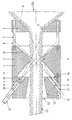
- Die Erfindung wird nachfolgend näher beschrieben unter Hinweis auf die Zeichnung, welche schematisch einen Schnitt durch eine Vorrichtung gemäss der Erfindung zeigt.
- Wie in der Zeichnung dargestellt, ist die Vorrichtung 1 rotationssymmetrisch aufgebaut und besteht aus einem Einlassteil 2, einem Mittelteil 3 und einem Auslassteil 4, durch welche Teile sich eine Durchlassöffnung 24 erstreckt.
- Der Einlassteil 2 ist ausgeführt als ein Rondell mit einem innen abgerundeten Einlassabschnitt 5 und einer kegelförmigen Einlassfläche 6. Der Brustwinkel der Fläche 6 kann 60° betragen.
- Der Einlassteil 2 ist mittels einer Anzahl Bolzen 7 an und in einem gewissen Abstand zu dem Mittelteil 3 angebracht, wobei eine umlaufende Wasserauslassöffnung 8 geschaffen wird.
- Der Mittelteil 3 besitzt ebenso einen inneren, abgerundeten Mittelabschnitt 9, der auf beiden Seiten von kegelförmigen Flächen 10 und 11 abgegrenzt ist. Der Brustwinkel der Zuführfläche 10 kann 40° und der der Abführfläche 11 50° betragen. Die Durchmesser des Mittelabschnittes 9 kann gleich dem des Einlassabschnittes 5 sein.
- Der Auslassteil 4 ist auf dem Mittelteil 3 mit Schrauben 12 befestigt.
- Der Auslassteil 4 besitzt einen inneren, abgerundeten Auslassabschnitt 13, der auf der Anlaufseite von einer lotrechten Fläche 14 und auf der Ablaufseite von einer kegelförmigen Ausführfläche 15 abgegrenzt ist, wovon die letztere in Richtung auf ein Auslassende 16 zunehmenden Durchmesser aufweist.
- Der Auslassabschnitt 13 kann einen etwas grösseren Durchmesser aufweisen als die Abschnitte 5 und 9.
- Im Auslassteil 4 sind Kanäle 17 vorgesehen, deren Zentrumlinien schräg vorwärts zum Mittelabchnitt 9 gerichtet sind und sich in einem Punkte der Symmetrieachse der Vorrichtung schneiden.
- Es sind wenigstens zwei entgegengesetzte Anordnungen von Kanälen 17 vorhanden, die in zwei zueinander winkelrechten Ebenen vorgesehen sind. Die Kanäle können in einem Winkel von 55° zur Symmetrieachse der Vorrichtung angeordnet sein.
- In den Kanälen 17 sind Verteilerdüsen 18 vorgesehen, deren Verteilerwinkel einstellbar ist. Die Düsen sind an einem zylinderförmigen Halter 19 angebracht, welcher mit leichter Gleitpassung in den Kanälen 17 angeordnet ist. Der Halter 19 kann im Verhältnis zu den Kanälen 17 steuerbar sein, indem eine Feder 20 am Halter mit einer Nute 21 in Eingriff steht, welche Nute in den Kanälen vorgesehen ist, und der Halter lässt sich in seiner Lage mit Hilfe einer nicht gezeigten Schraube festspannen.
- An dem Halter 19 sind Schläuche 22 festgesetzt, durch welche Wasser von einer nicht gezeigten Pumpe zugeführt wird.
- Die Kanäle 17 sind folglich derart im Verhältnis zum Mittelteil 3 angeordnet und ausgerichtet, dass die Strahlenbündel von den Düsen ungehindert durch den Mittelabschnitt 9 und durch ein Fischnetz passieren können, welches durch die Vorrichtung gezogen wird. Das Fischnetz wird von den Wasserstrahlen zentriert und leicht zusammen gedrückt, so dass es die Abschnitte 9 und 13 nicht berührt.
- Hierbei wird der Widerstand gegen das Passieren des Netzes vermindert und das Netz lässt sich leicht von Hand durch die Vorrichtung ziehen.
- Während des Reinigens wird Luft durch das Ende 16 eingesaugt. Indem statischer Druck in Geschwindigkeitsdruck umgesetzt wird, geschieht ein effektives Mischen von Wasser und Luft, so durch die Reinigungswirkung wesentlich verbessert wird. Das verschmutzte Wasser verlässt die Vorrichtung durch die Wasserauslassöffnung 8.
- Zur Reinigung lässt sich Salzwasser verwenden und die Vorrichtung kann auf einem Schiff angebracht werden, so dass die Fischnetze unmittelbar nach einem Fischfang gereinigt werden können.
- Die Vorrichtung lässt sich aus Metall oder aus Polyäthylen herstellen.
- Die gezeigte und beschriebene Ausführungsform soll nur als Beispiel der Erfindung dienen.
Claims (3)
- Vorrichtung zum Reinigen von Fischnetzen, dadurch gekennzeichnet, dass die Vorrichtung (1) zentral eine im wesentlichen zylinderförmige oder schwach kegelförmige Durchlassöffnung (24) für ein Netz (23) aufweist, welche Öffnung gebildet wird von einem Einlassabschnitt (5) in einem Einlassteil (2), einem Mittelabschnitt (9) in einem Mittelteil (3) und einem Auslassabschnitt (13) in einem Auslassteil (4), dass im Bereich zwischen dem Einlassteil (2) und dem Mittelteil (3) sich eine Auslassöffnung (8) für Wasser befindet, dass der Mittelabschnitt (9) im Mittelteil (3) auf der einen Seite an eine kegelförmige Zuführfläche (10) und auf der anderen an eine kegelförmige Abführfläche (11) angrenzt, dass im Auslassteil (4) wenigstens zwei entgegengesetzte Anordnungen von Düsen (18) in zwei zueinander winkelrechten Ebenen angebracht sind, dass die Düsen (18) mit ihrer Strahlrichtung schräg nach vorne zum Mittelabschnitt (9) gerichtet und derart angeordnet sind, dass die Strahlen an der Abführfläche (11) entlang, durch das Netz (23) im Bereich des Mittelabschnittes (9), an der Zuführfläche (10) vorbei und durch die Wasserauslassöffnung (8) hinaus frei passieren können, ohne wesentlichen Widerstand von einem Teil der Vorrichtung zu erfahren.
- Vorrichtung nach Anspruch 1, dadurch gekennzeichnet, dass die Düsen (18) derart ausgeführt und angeordnet sind, dass sowohl der Verteilerwinkel als auch der Abstand der Düsen von der Mittellinie der Vorrichtung einstellbar sind.
- Vorrichtung nach Anspruch 1, dadurch gekennzeichnet, dass der Auslassabschnitt (13) im Auslassteil (4) sich kegelförmig erweitert in Form einer Ausführfläche (15) zum Auslassende (16) hin.
Priority Applications (1)
| Application Number | Priority Date | Filing Date | Title |
|---|---|---|---|
| AT87111360T ATE71565T1 (de) | 1986-08-14 | 1987-08-06 | Vorrichtung zum reinigen von fischnetzen. |
Applications Claiming Priority (2)
| Application Number | Priority Date | Filing Date | Title |
|---|---|---|---|
| DK386686A DK157608C (da) | 1986-08-14 | 1986-08-14 | Aggregat til rensning af fiskegarn |
| DK3866/86 | 1986-08-14 |
Publications (3)
| Publication Number | Publication Date |
|---|---|
| EP0257397A2 EP0257397A2 (de) | 1988-03-02 |
| EP0257397A3 EP0257397A3 (en) | 1989-06-28 |
| EP0257397B1 true EP0257397B1 (de) | 1992-01-15 |
Family
ID=8127624
Family Applications (1)
| Application Number | Title | Priority Date | Filing Date |
|---|---|---|---|
| EP87111360A Expired - Lifetime EP0257397B1 (de) | 1986-08-14 | 1987-08-06 | Vorrichtung zum Reinigen von Fischnetzen |
Country Status (5)
| Country | Link |
|---|---|
| EP (1) | EP0257397B1 (de) |
| AT (1) | ATE71565T1 (de) |
| DE (1) | DE3776030D1 (de) |
| DK (1) | DK157608C (de) |
| ES (1) | ES2029460T3 (de) |
Families Citing this family (5)
| Publication number | Priority date | Publication date | Assignee | Title |
|---|---|---|---|---|
| FR2651639A1 (fr) * | 1989-09-08 | 1991-03-15 | Cnmh | Dispositif d'elimination des algues sur les filets de peche. |
| FR2672466B1 (fr) * | 1991-02-12 | 1993-06-11 | Maiziere Michel | Dispositif d'assistance de relevage de filets de peche par jets hydrodynamique. |
| SE469267B (sv) * | 1991-07-01 | 1993-06-14 | Candor Sweden Ab | Ytbehandlingsanordning, varvid ett medium under tryck riktas mot en loepande materialbana i en kavitet |
| FR2826597B1 (fr) * | 2001-06-28 | 2004-03-12 | Joseph Merlin | Machine de nettoyage de filets de peche ou de ralingues |
| JP3981064B2 (ja) | 2003-10-22 | 2007-09-26 | 株式会社カイジョー | 両面式超音波シャワー洗浄装置 |
Family Cites Families (5)
| Publication number | Priority date | Publication date | Assignee | Title |
|---|---|---|---|---|
| US2194565A (en) * | 1938-03-05 | 1940-03-26 | Kennecott Wire And Cable Compa | Device and method for cleaning or drying wire and other strand material |
| DE1422984A1 (de) * | 1959-10-21 | 1970-09-17 | Lipsner Smith Corp | Vorrichtung zum Reinigen eines mit Aufnahmen versehenen fotographischen Films durch Ultraschall |
| FR1470011A (fr) * | 1965-02-24 | 1967-02-17 | Kovofinis Narodni Podnik Ledec | Procédé et installation pour le traitement de surface de produits métallurgiques ou analogues |
| SE405259B (sv) * | 1975-03-25 | 1978-11-27 | Wennberg Ab C J | Sett vid avstrykning, tvettning i motstrom och torkning av i nagot medium ytbehandlade foremal av material i langa lengder samt anordning for genomforande av forfarandet |
| US4591390A (en) * | 1981-03-25 | 1986-05-27 | Shell Internationale Research Maatschappij B. V. | Cable cleaning system |
-
1986
- 1986-08-14 DK DK386686A patent/DK157608C/da not_active IP Right Cessation
-
1987
- 1987-08-06 EP EP87111360A patent/EP0257397B1/de not_active Expired - Lifetime
- 1987-08-06 AT AT87111360T patent/ATE71565T1/de not_active IP Right Cessation
- 1987-08-06 DE DE8787111360T patent/DE3776030D1/de not_active Expired - Lifetime
- 1987-08-06 ES ES198787111360T patent/ES2029460T3/es not_active Expired - Lifetime
Also Published As
| Publication number | Publication date |
|---|---|
| EP0257397A2 (de) | 1988-03-02 |
| ATE71565T1 (de) | 1992-02-15 |
| DK386686D0 (da) | 1986-08-14 |
| DE3776030D1 (de) | 1992-02-27 |
| DK386686A (da) | 1988-02-15 |
| ES2029460T3 (es) | 1992-08-16 |
| DK157608C (da) | 1990-06-18 |
| DK157608B (da) | 1990-01-29 |
| EP0257397A3 (en) | 1989-06-28 |
Similar Documents
| Publication | Publication Date | Title |
|---|---|---|
| DE68905728T2 (de) | Reinigungsapparat. | |
| DE69304335T2 (de) | Vorrichtung zum mischen von zwei flüssigkeiten mit unterschiedlicher temperatur | |
| EP0582191B1 (de) | Vorrichtung und Verfahren für die Behandlung von empfindlichen Oberflächen, insbesondere von Skulpturen | |
| DE102011007003B4 (de) | Bernoulli-Filter und Verfahren zum Filtrieren von Flüssigkeiten | |
| DE2135332A1 (de) | Vorrichtung zur homogenen Feinverteilung eines Strömungsmittels durch ein anderes | |
| DE1913713A1 (de) | Spritzduese | |
| DE3016804A1 (de) | Buerstenkopf fuer eine rohrreinigungsmaschine | |
| DE2243635B2 (de) | Verfahren und Vorrichtung zum Abfuhren des Bohrstaubes beim Gesteinsbohren mit Spulluft | |
| DE2627106A1 (de) | Vorrichtung zum bilden einer pulverschicht auf der oberflaeche eines gegenstandes | |
| DE2524146A1 (de) | Vorrichtung zum beimischen eines durch eine fluessigkeit abtragbaren, festen stoffes zu der fluessigkeit | |
| DE1290841B (de) | Wasserstrahl-Antriebseinrichtung fuer Wasscrfahrzeuge | |
| DE2753788A1 (de) | Vorrichtung zum zerstaeuben und dispergieren von fluida | |
| DE2928093A1 (de) | Vorrichtung zum abscheiden von feststoffen aus einem fluessigkeitsstrom | |
| EP0257397B1 (de) | Vorrichtung zum Reinigen von Fischnetzen | |
| DE2928698A1 (de) | Vorrichtung zur erzeugung eines mit schleifmittelteilchen versetzten fluessigkeitsstrahles (dispenser) | |
| DE1471630A1 (de) | Verfahren und Vorrichtung zur Reinigung von Gasen | |
| EP1475159B1 (de) | Sprühgerät für Beschichtungsmaterial, insbesondere Beschichtungspulver | |
| DE4417727A1 (de) | Schlauchbürste | |
| DE4129594C2 (de) | Vorrichtung zum Behandeln einer Flüssigkeit | |
| DE2417580A1 (de) | Verfahren und vorrichtung zum richten eines feste abriebpartikel enhaltenden fluessigkeitsstrahls auf die oberflaeche eines werkstuecks | |
| DD220770A3 (de) | Vorrichtung zum druckluftstrahlen | |
| DE2336925A1 (de) | Fliessmittel-mischkammer | |
| DE4313704C2 (de) | Vorrichtung zum Erzeugen eines mit einem Abrasivmittel versetzten Flüssigkeitsstrahles | |
| DE4312994C2 (de) | Vorrichtung zur Verspritzung von Suspensionen, insbesondere Mörteln | |
| DE69923211T2 (de) | Einrichtung zum antrieb von schiffen und düse hierfür |
Legal Events
| Date | Code | Title | Description |
|---|---|---|---|
| PUAI | Public reference made under article 153(3) epc to a published international application that has entered the european phase |
Free format text: ORIGINAL CODE: 0009012 |
|
| AK | Designated contracting states |
Kind code of ref document: A2 Designated state(s): AT BE CH DE ES FR GB GR IT LI LU NL SE |
|
| PUAL | Search report despatched |
Free format text: ORIGINAL CODE: 0009013 |
|
| AK | Designated contracting states |
Kind code of ref document: A3 Designated state(s): AT BE CH DE ES FR GB GR IT LI LU NL SE |
|
| 17P | Request for examination filed |
Effective date: 19890905 |
|
| 17Q | First examination report despatched |
Effective date: 19901127 |
|
| GRAA | (expected) grant |
Free format text: ORIGINAL CODE: 0009210 |
|
| AK | Designated contracting states |
Kind code of ref document: B1 Designated state(s): AT BE CH DE ES FR GB GR IT LI LU NL SE |
|
| PG25 | Lapsed in a contracting state [announced via postgrant information from national office to epo] |
Ref country code: NL Effective date: 19920115 Ref country code: IT Free format text: LAPSE BECAUSE OF FAILURE TO SUBMIT A TRANSLATION OF THE DESCRIPTION OR TO PAY THE FEE WITHIN THE PRE;WARNING: LAPSES OF ITALIAN PATENTS WITH EFFECTIVE DATE BEFORE 2007 MAY HAVE OCCURRED AT ANY TIME BEFORE 2007. THE CORRECT EFFECTIVE DATE MAY BE DIFFERENT FROM THE ONE RECORDED.SCRIBED TIME-LIMIT Effective date: 19920115 Ref country code: GR Free format text: LAPSE BECAUSE OF FAILURE TO SUBMIT A TRANSLATION OF THE DESCRIPTION OR TO PAY THE FEE WITHIN THE PRESCRIBED TIME-LIMIT Effective date: 19920115 Ref country code: GB Effective date: 19920115 Ref country code: BE Effective date: 19920115 |
|
| REF | Corresponds to: |
Ref document number: 71565 Country of ref document: AT Date of ref document: 19920215 Kind code of ref document: T |
|
| REF | Corresponds to: |
Ref document number: 3776030 Country of ref document: DE Date of ref document: 19920227 |
|
| ET | Fr: translation filed | ||
| NLV1 | Nl: lapsed or annulled due to failure to fulfill the requirements of art. 29p and 29m of the patents act | ||
| GBV | Gb: ep patent (uk) treated as always having been void in accordance with gb section 77(7)/1977 [no translation filed] | ||
| PG25 | Lapsed in a contracting state [announced via postgrant information from national office to epo] |
Ref country code: AT Effective date: 19920806 |
|
| REG | Reference to a national code |
Ref country code: ES Ref legal event code: FG2A Ref document number: 2029460 Country of ref document: ES Kind code of ref document: T3 |
|
| PG25 | Lapsed in a contracting state [announced via postgrant information from national office to epo] |
Ref country code: LU Free format text: LAPSE BECAUSE OF NON-PAYMENT OF DUE FEES Effective date: 19920831 Ref country code: LI Effective date: 19920831 Ref country code: CH Effective date: 19920831 |
|
| PLBE | No opposition filed within time limit |
Free format text: ORIGINAL CODE: 0009261 |
|
| STAA | Information on the status of an ep patent application or granted ep patent |
Free format text: STATUS: NO OPPOSITION FILED WITHIN TIME LIMIT |
|
| 26N | No opposition filed | ||
| REG | Reference to a national code |
Ref country code: CH Ref legal event code: AUV Free format text: DAS OBENGENANNTE PATENT IST, MANGELS BEZAHLUNG DER 6. JAHRESGEBUEHR GELOESCHT WORDEN. Ref country code: CH Ref legal event code: PL |
|
| EAL | Se: european patent in force in sweden |
Ref document number: 87111360.1 |
|
| PGFP | Annual fee paid to national office [announced via postgrant information from national office to epo] |
Ref country code: FR Payment date: 19950725 Year of fee payment: 9 |
|
| PGFP | Annual fee paid to national office [announced via postgrant information from national office to epo] |
Ref country code: ES Payment date: 19950726 Year of fee payment: 9 |
|
| PG25 | Lapsed in a contracting state [announced via postgrant information from national office to epo] |
Ref country code: ES Free format text: LAPSE BECAUSE OF THE APPLICANT RENOUNCES Effective date: 19960807 |
|
| PG25 | Lapsed in a contracting state [announced via postgrant information from national office to epo] |
Ref country code: FR Effective date: 19970430 |
|
| REG | Reference to a national code |
Ref country code: FR Ref legal event code: ST |
|
| REG | Reference to a national code |
Ref country code: ES Ref legal event code: FD2A Effective date: 19991007 |
|
| PGFP | Annual fee paid to national office [announced via postgrant information from national office to epo] |
Ref country code: SE Payment date: 20030530 Year of fee payment: 17 |
|
| PGFP | Annual fee paid to national office [announced via postgrant information from national office to epo] |
Ref country code: DE Payment date: 20031028 Year of fee payment: 17 |
|
| PG25 | Lapsed in a contracting state [announced via postgrant information from national office to epo] |
Ref country code: SE Free format text: LAPSE BECAUSE OF NON-PAYMENT OF DUE FEES Effective date: 20040807 |
|
| PG25 | Lapsed in a contracting state [announced via postgrant information from national office to epo] |
Ref country code: DE Free format text: LAPSE BECAUSE OF NON-PAYMENT OF DUE FEES Effective date: 20050301 |
|
| EUG | Se: european patent has lapsed |