EP0257006A2 - Procédé pour nettoyer le fond d'un bassin - Google Patents
Procédé pour nettoyer le fond d'un bassin Download PDFInfo
- Publication number
- EP0257006A2 EP0257006A2 EP87850226A EP87850226A EP0257006A2 EP 0257006 A2 EP0257006 A2 EP 0257006A2 EP 87850226 A EP87850226 A EP 87850226A EP 87850226 A EP87850226 A EP 87850226A EP 0257006 A2 EP0257006 A2 EP 0257006A2
- Authority
- EP
- European Patent Office
- Prior art keywords
- pool
- pool cleaner
- wall
- cleaner
- coupling position
- Prior art date
- Legal status (The legal status is an assumption and is not a legal conclusion. Google has not performed a legal analysis and makes no representation as to the accuracy of the status listed.)
- Granted
Links
Images


Classifications
-
- E—FIXED CONSTRUCTIONS
- E04—BUILDING
- E04H—BUILDINGS OR LIKE STRUCTURES FOR PARTICULAR PURPOSES; SWIMMING OR SPLASH BATHS OR POOLS; MASTS; FENCING; TENTS OR CANOPIES, IN GENERAL
- E04H4/00—Swimming or splash baths or pools
- E04H4/14—Parts, details or accessories not otherwise provided for
- E04H4/16—Parts, details or accessories not otherwise provided for specially adapted for cleaning
- E04H4/1654—Self-propelled cleaners
Definitions
- the invention relates to a method of cleaning the bottom of a pool with the aid of a self-propelling, motorised pool cleaner, the pool cleaner travelling to and fro, with parallel movement at change of direction, in straight paths between two opposite walls of the pool while collecting material lying at the bottom of the pool, said pool cleaner comprising control means arranged to emit control signals to the members governing movement of the pool cleaner, in order to change the direction of travel when encountering a wall of the pool.
- pool cleaners operating in various ways to clean the bottom of a pool.
- These pool cleaners comprise collecting members, usually in the form of rotating brushes arranged at two ends of the pool cleaner. These brushes collect loose material lying at the bottom of the pool, which is sucked up with the aid of a pump, into filter bags on the machine to be disposed of subsequently.
- the pool cleaner is propelled along the bottom of the pool by a drive motor.
- Two main principles pertain in moving a pool cleaner along the bottom of a pool.
- the pool cleaner In the first the pool cleaner is allowed to move along the bottom while being subjected to random changes of direction. It might, for instance, be time-controlled, or the changes of direction may occur when the cleaner encounters the edge of the pool, sensing devices causing the drive means to reverse direction and the pool cleaner to travel in arbitrary direction away from the wall.
- the random movement principle has considerable drawbacks, due both to its inefficiency since several outer regions will be covered several times, and to the cleaning being unsatisfactory since many areas will not be traversed at all and will therefore never be cleaned.
- the second principle is based on controlled movement of the pool cleaner so that it will move in overlapping, parallel paths and being accurately turned at the pool walls. Hitherto it has been necessary to use pool cleaners with reversible drives, operating in two directions, i.e. forwards and backwards. Suction capacity for both directions of travel had therefore to be provided, as well as brushes and sensing devices at both ends of the pool cleaner. Such machines are therefore relatively expensive.
- a pool cleaner with controlled travel across the entire pool is known through EP-A 83106211.1, for instance.
- the pool cleaner is run to and fro between opposite pool walls, travelling perpendicularly in towards a wall but leaving it at an angle to the previous path after reversal of the drive direction, so that it encounters the next wall at an angle and leaves it again at an angle.
- the changes in direction of travel are effected with the aid of two fenders, adjustable in longitudinal direction, arranged at each end of the apparatus, i.e. four fenders in all, which encounter the pool wall and align the cleaner in relation thereto.
- the fenders protrude the same distance and the pool cleaner will therefore back out perpendicularly from the wall, whereas the fenders protrude different lengths at the other end and the cleaner will therefore be aligned at .
- the cleaner will move diagonally over the previous path until upon reaching the opposite wall, it has been displaced one path width.
- the cleaner thus operates extremely inefficiently since at least half the surface already covered is cleaned again.
- the fenders must be accurately adjusted according to the width of the pool to prevent the overlap being even greater than 50% or parts not being cleaned. In practice such adjustment is extremely difficult and is extremely time-consuming if an optimum result is to be obtained. Furthermore, it is entirely unsuitable for automatic cleaning of pools of irregular shape since the same unsatisfactory results are obtained as with random movement.
- the object of the invention is to achieve a method of automatically cleaning the bottom of a pool, of the type described in the introduction which, although permitting a simpler and less expensive design for the pool cleaner, entails more efficient and reliable cleaning than previous methods have been able to offer.
- the pool cleaner after having travelled in a straight path towards one wall, being turned a half turn and simultaneously displaced laterally perpendicular to the initial direction of travel, the pool cleaner being thereafter driven on a path parallel to the initial direction of travel to the opposite wall of the pool, the pool cleaner being there again turned a half turn and simultaneously displaced laterally in the same direction as the lateral displacement at the previous turn, and the pool cleaner thereafter being driven back to the opposite wall of the pool, the process then being repeated until the desired bottom section has been covered.
- the main advantage is that the pool cleaner can be simpler and less expensive in design while still cleaning the pool more efficiently and at least as reliably as previously known methods.
- the pool cleaner need be provided with only a single collection means and need be designed to suck in water from only one direction. A pump with less capacity, and thus less expensive, is therefore sufficient.
- the parallel paths are obtained by only one control impulse at the turning positions and, since the pool cleaner travels in only one operating direction, its course-maintaining stability is increased.
- the machine can be made more compact so that the majority of its weight is taken by a smaller support member surface, the motor and pump being located immediately above or close to two drive wheels, for instance, thus giving high friction between support members and the bottom of the pool. Only one fender is required if the pool wall is utilized for aligning the pool cleaner.
- the pool cleaner shown in Figures 1 and 2 comprises a chassis 1, in which drive wheels 23 and a rear support wheel 4 are rotatably journalled.
- the drive wheels 2, 3 are connected to a reversible motor 5 via a transmission chain comprising gears of convention type, not shown in detail, couplings 23, 24 and drift shaft.
- the electric motor 5 also drives two brush rollers 7, 8 arranged on the same shaft, by way of two belt transmissions 9, 10.
- the brushes 7, 8 are movably supported in relation to the drive shaft by means of pivotably journalled brush holders 11, 12 at the sides of the pool cleaner 1 on the drive shaft.
- Each brush holder 11, 12 is provided with a slip-roll 13 having a surface of low-friction material over which the belt 9 glides.
- the slip-roll 13 has two functions: that of regulating the belt tension and increasing the angle at which the belt 9 surrounds the brush-roller axle and also that of preventing plasters or similar matter collected up from entering and catching between the belt 9 and the belt groove.
- the pool cleaner also includes a pump with pump housing 21 and pump motor 20, which sucks up water and material collected by the brushes 7,8 and carries it to a store permeable to water, such as a filter bag 15.
- a pump with pump housing 21 and pump motor 20, which sucks up water and material collected by the brushes 7,8 and carries it to a store permeable to water, such as a filter bag 15.
- a fender 16 is provided at the rear of the pool cleaner, to align it with a pool wall after a turning movement.
- the fender 16, best illustrated in Figure 2 comprises two stops 17, 18 at the sides of the cleaner, arranged so that a surface at a tangent to these stops 17, 18 forms a right angle to the direction of travel of the pool cleaner.
- the driven support wheel 4 is provided with an impulse emitter and an impulse receiver 22 is arranged on the chassis 1.
- impulse generators are known per se and many types are possible.
- the impulse emission may be purely mechanical, for instance, utilizing one or more spring tongues actuating a switch, for instance, or it may occur with out contacts, inductively or capacitively, for instance, as is deemed expedient.
- the number of transducers is of course dependent on the requirement.
- Each driving wheel 2, 3 is provided with a separate magnetic coupling 23 and 24, respectively, allowing the relevant drive wheel 2, 3 to be coupled to or released from the drive shaft.
- both wheels 2 and 3 are connected to the drive shaft so that the pool cleaner moves along a straight path when the drive motor 5 receives current.
- the transformer 25 transforms the supply power to 48 V alternating voltage.
- the pump motor 20 communicates directly with the transformer 25 and is thus always driven when there is voltage at the transformer output. Water is drawn into the pump housing 21 and out into the filter 15, where solid material is caught while the water flows through.
- the power supply to the magnetic couplings 23, 24 of the drive motor 5 is controlled by a circuit 26 which, via a lead 27, is connected to the impulse sensor 22 and, via a lead 28, to an operating box 29 which is preferably designed to be portable and includes switches for switching between automatic and manual operation.
- the operating box is provided with buttons for oscillating movements in various directions and for driving forwards or backwards when in manual mode.
- the apparatus is driven forwards by the two wheels 2, 3 being driven by the drive shaft.
- the impulse sensor 22 emits signals to the control means 26 which comprises a time-delay circuit which is cleared by a signal from the sensor and releases a signal after a time interval exceeding that between two impulses.
- This time-delayed signal now activates a control program during which the current delay to the drive motor 5 is pole-inverted, the drive thus being reversed and the cleaner moving backwards. Reversing is time-controlled so that the apparatus moves back about 5 dm, after which the current supply to one of the magnetic couplings 23, 24 is disconnected for a predetermined period. Since one of the wheels 2, 3 is driven and the other not, the whole apparatus will swing around.
- the predetermined time interval is such in relation to the speed of the pool cleaner that it will be turned half a turn.
- both magnetic couplings 23, 24 will receive current.
- the apparatus will then move back until it is stopped by the pool wall and, with the aid of the fender 16, is aligned to the wall.
- After a suitable period for alignment the direction of drive is again reversed so that the pool cleaner travels along the bottom of the pool in the opposite direction.
- the process triggered by sensor 22 is then repeated at the opposite wall, with the difference that the control means 26 now disconnects the current supply to the other of the magnetic couplings 24, 23, thus releasing the second wheel 3, 2 from the drive shaft while the wheel 2, 3 which was not driven in the previous turn, will now be driven.
- the procedure is repeated until the desired pool section has been covered, the driving wheels 2, 3 being alternately connected and disconnected to the drive shaft at the turning points.
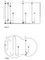
- Figures 3 and 4 show various examples of the method according to the invention, curve A in Figure 3 corresponding to the procedure described above so that no further explanation is required here.
- the larger arrows in the figures indicate forward direction whereas the smaller arrows indicate that the apparatus is reversing.
- control means 26 is arranged to steer the cleaner towards a pool wall along a straight path, after which it is backed a suitable distance from the wall, 5 dm for instance, whereupon it is turned 180 0 and again driven forwards towards the opposite pool edge.
- This procedure is particularly suitable for pools of irregular shape since the cleaner is not aligned to a wall behind.
- Curve D in Figure 2 also describes a procedure particularly suitable for irregularly shaped pools.
- the pool cleaner is here provided with sensors capable of detecting the wall while still at a distance therefrom.
- the pool cleaner At a suitable distance from the wall the pool cleaner is swung a half turn and then travels towards the opposite wall where it again swings round and returns parallel to the initial direction of travel, and so on.
- This machine can of course also be used for rectangular pools.
- control means governing the movement in response to detection of a pool wall by the sensors may contain a running program specifically programmed for the pool in question where the turning movements and the various driving lengths in an irregularly shaped pool are time-controlled.
- curve B in Figure 3 the cleaner is run until it is stopped by a pool wall, after which the drive is reversed for about 7 dm and then again reversed at the same time as one driving wheel is driven and the other allowed to run free.
- the drive is again connected for the second wheel, at the same time as the motor is reversed so that the machine backs towards the wall, stops and is aligned therewith, after which the drive is reversed so that the machine travels towards the other wall where the procedure is repeated.
- Curve C illustrates a procedure in which the pool cleaner is provided with sensors capable of sensing the pool wall when still at a distance therefrom. The pool cleaner is stopped at a suitable distance from the wall, after which the control program causes it to turn half a turn, back to the wall, align itself with the wall and then run forwards.
Landscapes
- Engineering & Computer Science (AREA)
- Architecture (AREA)
- Civil Engineering (AREA)
- Structural Engineering (AREA)
- Cleaning In General (AREA)
- Control Of Position, Course, Altitude, Or Attitude Of Moving Bodies (AREA)
- Electric Suction Cleaners (AREA)
- Electric Vacuum Cleaner (AREA)
- Cleaning Or Drying Semiconductors (AREA)
Priority Applications (1)
| Application Number | Priority Date | Filing Date | Title |
|---|---|---|---|
| AT87850226T ATE52301T1 (de) | 1986-08-20 | 1987-07-13 | Verfahren zur bodenreinigung eines beckens. |
Applications Claiming Priority (2)
| Application Number | Priority Date | Filing Date | Title |
|---|---|---|---|
| SE8603505 | 1986-08-20 | ||
| SE8603505A SE465629B (sv) | 1986-08-20 | 1986-08-20 | Foerfarande foer rengoering av en bassaengbotten |
Publications (3)
| Publication Number | Publication Date |
|---|---|
| EP0257006A2 true EP0257006A2 (fr) | 1988-02-24 |
| EP0257006A3 EP0257006A3 (en) | 1988-09-21 |
| EP0257006B1 EP0257006B1 (fr) | 1990-04-25 |
Family
ID=20365348
Family Applications (1)
| Application Number | Title | Priority Date | Filing Date |
|---|---|---|---|
| EP87850226A Expired - Lifetime EP0257006B1 (fr) | 1986-08-20 | 1987-07-13 | Procédé pour nettoyer le fond d'un bassin |
Country Status (5)
| Country | Link |
|---|---|
| US (1) | US4786334A (fr) |
| EP (1) | EP0257006B1 (fr) |
| AT (1) | ATE52301T1 (fr) |
| DE (1) | DE3762440D1 (fr) |
| SE (1) | SE465629B (fr) |
Cited By (7)
| Publication number | Priority date | Publication date | Assignee | Title |
|---|---|---|---|---|
| EP0352487A1 (fr) * | 1988-06-28 | 1990-01-31 | EGATECHNICS S.r.l. | Appareil automobile pour nettoyer automatiquement les piscines |
| EP0465453A1 (fr) * | 1990-07-02 | 1992-01-08 | Jean Albert François SÜNNEN | Perfectionnement aux robots de service |
| EP0483677A2 (fr) * | 1990-10-31 | 1992-05-06 | 3S Systemtechnik Ag | Méthode de fonctionnement et appareil de nettoyage d'un bassin de natation |
| FR2692617A1 (fr) * | 1992-05-29 | 1993-12-24 | De Lavergne Christian | Flotteurs d'hivernage sans lest destinés à éviter en cas de gel la détérioration des parois des piscines. |
| EP0483470B1 (fr) * | 1990-10-31 | 1996-05-08 | 3S Systemtechnik Ag | Appareil de nettoyage à auto-propulsion,en particulier pour bassins de natation |
| EP0989256A1 (fr) * | 1998-09-23 | 2000-03-29 | 3S Systemtechnik Ag | Procédé de travail et appareil de nettoyage pour nettoyer une piscine |
| EP1826338A2 (fr) * | 2006-02-24 | 2007-08-29 | 3S Systemtechnik AG | Procédé de travail et appareil de nettoyage destiné au nettoyage d'une piscine |
Families Citing this family (23)
| Publication number | Priority date | Publication date | Assignee | Title |
|---|---|---|---|---|
| US6398878B1 (en) * | 1997-05-06 | 2002-06-04 | Melvyn L. Henkin | Automatic pool cleaner including motion sensor and repositioning means |
| SE510376C2 (sv) * | 1997-09-26 | 1999-05-17 | Weda Poolcleaner Ab | Automatisk bassängrenare |
| US6099658A (en) * | 1998-09-29 | 2000-08-08 | Aqua Products Inc. | Apparatus and method of operation for high-speed swimming pool cleaner |
| US6299699B1 (en) * | 1999-04-01 | 2001-10-09 | Aqua Products Inc. | Pool cleaner directional control method and apparatus |
| US6758226B2 (en) * | 1999-04-01 | 2004-07-06 | Aqua Products Inc. | Motion detection and control for automated pool cleaner |
| US6478911B1 (en) | 2000-09-27 | 2002-11-12 | Guardian Industries Corp. | Vacuum IG window unit with edge seal formed via microwave curing, and corresponding method of making the same |
| EP1512810B1 (fr) | 2001-10-15 | 2008-11-26 | Aqua Products Inc. | Appareil et procédé de nettoyage de piscine |
| KR100446800B1 (ko) * | 2002-10-18 | 2004-09-04 | 윤동현 | 양어장의 수조바닥 세척장치 |
| WO2005035909A1 (fr) * | 2003-10-14 | 2005-04-21 | Maytronics Ltd. | Robot de nettoyage de piscine sans fil |
| US8241430B2 (en) * | 2003-11-04 | 2012-08-14 | Aqua Products, Inc. | Directional control method for dual brush robotic pool cleaners |
| CN100434641C (zh) * | 2003-11-04 | 2008-11-19 | 水溶液产品公司 | 用于控制自动推动机器人池清洁器的移动方向的设备和方法 |
| US9051750B2 (en) | 2003-11-04 | 2015-06-09 | Aqua Products, Inc. | Directional control for dual brush robotic pool cleaners |
| US6984315B2 (en) | 2003-12-16 | 2006-01-10 | Dolton Iii Edward Gerard | Pool cleaning device |
| US6942790B1 (en) | 2004-06-10 | 2005-09-13 | Edward Dolton | Open-air filtration cleaning device for pools and hot tubs |
| WO2007047827A1 (fr) * | 2005-10-18 | 2007-04-26 | Aquatron Inc. | Procédé et appareil de nettoyage de piscine programmable sur mesure |
| US7690066B2 (en) * | 2005-11-03 | 2010-04-06 | Zodiac Pool Care, Inc. | Automatic pool cleaner |
| US7621014B2 (en) * | 2006-09-29 | 2009-11-24 | Aquatron Llc | Method for controlling twisting of pool cleaner power cable |
| US20080099409A1 (en) * | 2006-10-26 | 2008-05-01 | Aquatron Robotic Systems Ltd. | Swimming pool robot |
| ES2344821B1 (es) * | 2007-10-11 | 2011-07-11 | Fanor, S.L. | Robot limpia-fondos para vasos de piscinas. |
| US20180209161A1 (en) * | 2015-03-31 | 2018-07-26 | Benjamin Fertic | Pool cleaning device |
| US10619371B2 (en) | 2015-06-22 | 2020-04-14 | Aqua Products, Inc. | Robotic cleaner with extended brush assembly |
| ES2906710T3 (es) * | 2016-09-13 | 2022-04-20 | Maytronics Ltd | Robot de limpieza de piscinas |
| CN107377553B (zh) * | 2017-07-20 | 2023-05-26 | 芜湖华衍水务有限公司 | 一种池体清洗设备 |
Citations (5)
| Publication number | Priority date | Publication date | Assignee | Title |
|---|---|---|---|---|
| US2988762A (en) * | 1960-02-08 | 1961-06-20 | Hugh H Babcock | Self-steering submarine suction cleaner |
| DE1238649B (de) * | 1964-02-08 | 1967-04-13 | Walter Haack | Bodenreinigungs- und Behandlungsgeraet fuer Schwimmbecken |
| US3753265A (en) * | 1971-03-15 | 1973-08-21 | S Wulc | Translatable suction cleaning vehicle |
| DE8107667U1 (de) * | 1981-03-17 | 1982-02-25 | Corvinus, Rolf, 6450 Hanau | Geraet zum reinigen eines schwimmbeckens |
| EP0099489A1 (fr) * | 1982-07-05 | 1984-02-01 | Sommer, Schenk AG | Procédé et appareil de nettoyage d'un bassin |
Family Cites Families (3)
| Publication number | Priority date | Publication date | Assignee | Title |
|---|---|---|---|---|
| US3439368A (en) * | 1967-01-03 | 1969-04-22 | Robert R Myers | Swimming pool cleaner |
| US3950809A (en) * | 1974-11-08 | 1976-04-20 | Rudolf Emil Schatzmann | Combination sweeper and vacuum cleaner for swimming pools |
| US4651376A (en) * | 1985-10-04 | 1987-03-24 | Ford Ralph W | Underwater self-contained cleaning assembly |
-
1986
- 1986-08-20 SE SE8603505A patent/SE465629B/sv not_active IP Right Cessation
-
1987
- 1987-07-13 AT AT87850226T patent/ATE52301T1/de not_active IP Right Cessation
- 1987-07-13 EP EP87850226A patent/EP0257006B1/fr not_active Expired - Lifetime
- 1987-07-13 DE DE8787850226T patent/DE3762440D1/de not_active Expired - Lifetime
- 1987-08-05 US US07/082,047 patent/US4786334A/en not_active Expired - Fee Related
Patent Citations (5)
| Publication number | Priority date | Publication date | Assignee | Title |
|---|---|---|---|---|
| US2988762A (en) * | 1960-02-08 | 1961-06-20 | Hugh H Babcock | Self-steering submarine suction cleaner |
| DE1238649B (de) * | 1964-02-08 | 1967-04-13 | Walter Haack | Bodenreinigungs- und Behandlungsgeraet fuer Schwimmbecken |
| US3753265A (en) * | 1971-03-15 | 1973-08-21 | S Wulc | Translatable suction cleaning vehicle |
| DE8107667U1 (de) * | 1981-03-17 | 1982-02-25 | Corvinus, Rolf, 6450 Hanau | Geraet zum reinigen eines schwimmbeckens |
| EP0099489A1 (fr) * | 1982-07-05 | 1984-02-01 | Sommer, Schenk AG | Procédé et appareil de nettoyage d'un bassin |
Cited By (14)
| Publication number | Priority date | Publication date | Assignee | Title |
|---|---|---|---|---|
| EP0352487A1 (fr) * | 1988-06-28 | 1990-01-31 | EGATECHNICS S.r.l. | Appareil automobile pour nettoyer automatiquement les piscines |
| EP0465453A1 (fr) * | 1990-07-02 | 1992-01-08 | Jean Albert François SÜNNEN | Perfectionnement aux robots de service |
| BE1003703A3 (fr) * | 1990-07-02 | 1992-05-26 | Sunnen Jean | Perfectionnement aux robots de service. |
| EP0483470B1 (fr) * | 1990-10-31 | 1996-05-08 | 3S Systemtechnik Ag | Appareil de nettoyage à auto-propulsion,en particulier pour bassins de natation |
| EP0483677A2 (fr) * | 1990-10-31 | 1992-05-06 | 3S Systemtechnik Ag | Méthode de fonctionnement et appareil de nettoyage d'un bassin de natation |
| EP0483677A3 (en) * | 1990-10-31 | 1992-09-23 | 3S Systemtechnik Ag | Functioning method and cleaning device for swimming pools |
| US5256207A (en) * | 1990-10-31 | 1993-10-26 | 3S Systemtechnik Ag | Process for cleaning a swimming pool |
| FR2692617A1 (fr) * | 1992-05-29 | 1993-12-24 | De Lavergne Christian | Flotteurs d'hivernage sans lest destinés à éviter en cas de gel la détérioration des parois des piscines. |
| EP0989256A1 (fr) * | 1998-09-23 | 2000-03-29 | 3S Systemtechnik Ag | Procédé de travail et appareil de nettoyage pour nettoyer une piscine |
| US6309468B1 (en) | 1998-09-23 | 2001-10-30 | 3S Systemtechnik Ag | Working method and cleaning device for cleaning a swimming pool |
| EP1826338A2 (fr) * | 2006-02-24 | 2007-08-29 | 3S Systemtechnik AG | Procédé de travail et appareil de nettoyage destiné au nettoyage d'une piscine |
| EP1826338A3 (fr) * | 2006-02-24 | 2008-07-09 | 3S Systemtechnik AG | Procédé de travail et appareil de nettoyage destiné au nettoyage d'une piscine |
| US7682461B2 (en) | 2006-02-24 | 2010-03-23 | 3S Systemtechnik Ag | Working method and cleaning device to clean a swimming pool |
| US7987543B2 (en) | 2006-02-24 | 2011-08-02 | 3S Systemtechnik Ag | Working method and cleaning device to clean a swimming pool |
Also Published As
| Publication number | Publication date |
|---|---|
| EP0257006B1 (fr) | 1990-04-25 |
| SE465629B (sv) | 1991-10-07 |
| SE8603505L (sv) | 1988-02-21 |
| SE8603505D0 (sv) | 1986-08-20 |
| EP0257006A3 (en) | 1988-09-21 |
| US4786334A (en) | 1988-11-22 |
| ATE52301T1 (de) | 1990-05-15 |
| DE3762440D1 (de) | 1990-05-31 |
Similar Documents
| Publication | Publication Date | Title |
|---|---|---|
| US4786334A (en) | Method of cleaning the bottom of a pool | |
| AU761745B2 (en) | Robotic floor cleaning device | |
| DE69821659T2 (de) | Reinigungsroboter | |
| JPH0732751B2 (ja) | 自走式掃除機 | |
| US6815918B2 (en) | Pool cleaning method and apparatus | |
| JP2520732B2 (ja) | 電気掃除機の吸込口体 | |
| GB2344900A (en) | Robotic floor cleaning device with obstacle detection | |
| JP2002355204A (ja) | 自走式電気掃除機 | |
| JPS62292126A (ja) | 自走式掃除機 | |
| GB1342633A (en) | Self-steering vehicles | |
| JPH0584210A (ja) | 床面清掃ロボツト | |
| RU96123766A (ru) | Пылесос | |
| KR20030046325A (ko) | 자주식청소장치 및 자주식청소방법 | |
| US2950772A (en) | Electrically propelled household vacuum cleaner | |
| JP4621544B2 (ja) | 吸込口体及びこれを備える電気掃除機 | |
| JPH04328607A (ja) | 掃除ロボット | |
| RU2707821C2 (ru) | Пылесос и способ управления данным пылесосом | |
| US3056152A (en) | Electrically propelled household devices | |
| KR100283865B1 (ko) | 로봇청소기의청소제어장치및그방법 | |
| JP3314469B2 (ja) | 自走式掃除機 | |
| JPH05207955A (ja) | 自走式掃除機 | |
| KR100514993B1 (ko) | 무인청소기 | |
| KR930000310Y1 (ko) | 물걸레기능을 가진 전기청소기 | |
| JP3036863B2 (ja) | 走行ロボット | |
| KR20080077488A (ko) | 자동 주행 청소기 및 그 제어방법 |
Legal Events
| Date | Code | Title | Description |
|---|---|---|---|
| PUAI | Public reference made under article 153(3) epc to a published international application that has entered the european phase |
Free format text: ORIGINAL CODE: 0009012 |
|
| AK | Designated contracting states |
Kind code of ref document: A2 Designated state(s): AT BE CH DE ES FR GB GR IT LI NL |
|
| PUAL | Search report despatched |
Free format text: ORIGINAL CODE: 0009013 |
|
| AK | Designated contracting states |
Kind code of ref document: A3 Designated state(s): AT BE CH DE ES FR GB GR IT LI NL |
|
| 17P | Request for examination filed |
Effective date: 19890118 |
|
| 17Q | First examination report despatched |
Effective date: 19890904 |
|
| GRAA | (expected) grant |
Free format text: ORIGINAL CODE: 0009210 |
|
| AK | Designated contracting states |
Kind code of ref document: B1 Designated state(s): AT BE CH DE ES FR GB GR IT LI NL |
|
| PG25 | Lapsed in a contracting state [announced via postgrant information from national office to epo] |
Ref country code: IT Free format text: LAPSE BECAUSE OF FAILURE TO SUBMIT A TRANSLATION OF THE DESCRIPTION OR TO PAY THE FEE WITHIN THE PRE;WARNING: LAPSES OF ITALIAN PATENTS WITH EFFECTIVE DATE BEFORE 2007 MAY HAVE OCCURRED AT ANY TIME BEFORE 2007. THE CORRECT EFFECTIVE DATE MAY BE DIFFERENT FROM THE ONE RECORDED.SCRIBED TIME-LIMIT Effective date: 19900425 Ref country code: GR Free format text: LAPSE BECAUSE OF FAILURE TO SUBMIT A TRANSLATION OF THE DESCRIPTION OR TO PAY THE FEE WITHIN THE PRESCRIBED TIME-LIMIT Effective date: 19900425 Ref country code: NL Effective date: 19900425 Ref country code: BE Effective date: 19900425 Ref country code: AT Effective date: 19900425 |
|
| REF | Corresponds to: |
Ref document number: 52301 Country of ref document: AT Date of ref document: 19900515 Kind code of ref document: T |
|
| REF | Corresponds to: |
Ref document number: 3762440 Country of ref document: DE Date of ref document: 19900531 |
|
| ET | Fr: translation filed | ||
| PG25 | Lapsed in a contracting state [announced via postgrant information from national office to epo] |
Ref country code: ES Free format text: LAPSE BECAUSE OF FAILURE TO SUBMIT A TRANSLATION OF THE DESCRIPTION OR TO PAY THE FEE WITHIN THE PRESCRIBED TIME-LIMIT Effective date: 19900805 |
|
| NLV1 | Nl: lapsed or annulled due to failure to fulfill the requirements of art. 29p and 29m of the patents act | ||
| PLBE | No opposition filed within time limit |
Free format text: ORIGINAL CODE: 0009261 |
|
| STAA | Information on the status of an ep patent application or granted ep patent |
Free format text: STATUS: NO OPPOSITION FILED WITHIN TIME LIMIT |
|
| 26N | No opposition filed | ||
| PGFP | Annual fee paid to national office [announced via postgrant information from national office to epo] |
Ref country code: GB Payment date: 19910712 Year of fee payment: 5 |
|
| PGFP | Annual fee paid to national office [announced via postgrant information from national office to epo] |
Ref country code: FR Payment date: 19910726 Year of fee payment: 5 |
|
| PGFP | Annual fee paid to national office [announced via postgrant information from national office to epo] |
Ref country code: CH Payment date: 19911029 Year of fee payment: 5 |
|
| PG25 | Lapsed in a contracting state [announced via postgrant information from national office to epo] |
Ref country code: GB Effective date: 19920713 |
|
| PGFP | Annual fee paid to national office [announced via postgrant information from national office to epo] |
Ref country code: DE Payment date: 19920714 Year of fee payment: 6 |
|
| PG25 | Lapsed in a contracting state [announced via postgrant information from national office to epo] |
Ref country code: LI Effective date: 19920731 Ref country code: CH Effective date: 19920731 |
|
| GBPC | Gb: european patent ceased through non-payment of renewal fee |
Effective date: 19920713 |
|
| PG25 | Lapsed in a contracting state [announced via postgrant information from national office to epo] |
Ref country code: FR Effective date: 19930331 |
|
| REG | Reference to a national code |
Ref country code: CH Ref legal event code: PL |
|
| REG | Reference to a national code |
Ref country code: FR Ref legal event code: ST |
|
| PG25 | Lapsed in a contracting state [announced via postgrant information from national office to epo] |
Ref country code: DE Effective date: 19940401 |