EP0253003B1 - Récipient de forme plate pour confiseries, en particulier calendrier d'Avent - Google Patents
Récipient de forme plate pour confiseries, en particulier calendrier d'Avent Download PDFInfo
- Publication number
- EP0253003B1 EP0253003B1 EP86109567A EP86109567A EP0253003B1 EP 0253003 B1 EP0253003 B1 EP 0253003B1 EP 86109567 A EP86109567 A EP 86109567A EP 86109567 A EP86109567 A EP 86109567A EP 0253003 B1 EP0253003 B1 EP 0253003B1
- Authority
- EP
- European Patent Office
- Prior art keywords
- container
- opening
- rear wall
- front wall
- wall
- Prior art date
- Legal status (The legal status is an assumption and is not a legal conclusion. Google has not performed a legal analysis and makes no representation as to the accuracy of the status listed.)
- Expired - Lifetime
Links
Images

Classifications
-
- B—PERFORMING OPERATIONS; TRANSPORTING
- B65—CONVEYING; PACKING; STORING; HANDLING THIN OR FILAMENTARY MATERIAL
- B65D—CONTAINERS FOR STORAGE OR TRANSPORT OF ARTICLES OR MATERIALS, e.g. BAGS, BARRELS, BOTTLES, BOXES, CANS, CARTONS, CRATES, DRUMS, JARS, TANKS, HOPPERS, FORWARDING CONTAINERS; ACCESSORIES, CLOSURES, OR FITTINGS THEREFOR; PACKAGING ELEMENTS; PACKAGES
- B65D5/00—Rigid or semi-rigid containers of polygonal cross-section, e.g. boxes, cartons or trays, formed by folding or erecting one or more blanks made of paper
- B65D5/42—Details of containers or of foldable or erectable container blanks
- B65D5/4291—Containers provided with an acoustic device, e.g. for indicating opening of the package
-
- B—PERFORMING OPERATIONS; TRANSPORTING
- B65—CONVEYING; PACKING; STORING; HANDLING THIN OR FILAMENTARY MATERIAL
- B65D—CONTAINERS FOR STORAGE OR TRANSPORT OF ARTICLES OR MATERIALS, e.g. BAGS, BARRELS, BOTTLES, BOXES, CANS, CARTONS, CRATES, DRUMS, JARS, TANKS, HOPPERS, FORWARDING CONTAINERS; ACCESSORIES, CLOSURES, OR FITTINGS THEREFOR; PACKAGING ELEMENTS; PACKAGES
- B65D85/00—Containers, packaging elements or packages, specially adapted for particular articles or materials
- B65D85/60—Containers, packaging elements or packages, specially adapted for particular articles or materials for sweets or like confectionery products
-
- G—PHYSICS
- G09—EDUCATION; CRYPTOGRAPHY; DISPLAY; ADVERTISING; SEALS
- G09D—RAILWAY OR LIKE TIME OR FARE TABLES; PERPETUAL CALENDARS
- G09D3/00—Perpetual calendars
Definitions
- the invention relates to a flat container for confectionery, in particular a wall calendar, according to the preamble of claim 1.
- a flat container or wall calendar for confectionery of the specified type is already known (DE-U-85 12 998), which is used in particular as an advent calendar, the front wall being provided with 24 flaps or small doors, each of which can be opened along a fold line are so that the confectionery located behind them in the respective recess of the molded film insert can be removed. Since these advent calendars are given away at Christmas time, the outside of their front wall is usually designed as a picture with Christmas motifs in particular.
- the game device set in the interior of the flat container increases the gift value of such advent calendars and offers an additional incentive to buy.
- the cardboard outer casing is formed by several cardboard blanks which are combined to form the outer casing by folding and gluing processes. This production is relatively complex, and in addition, damage or unwanted actuation of the game device can occur in the use of the flat container or in storage and shipping as a result of its inadequate shielding by the outer casing made of cardboard.
- the invention has for its object to provide a flat container for confectionery, in particular wall calendars, with a game device increasing its gift value, which is simplified in its manufacture, has good manageability and offers the game device reliable protection against undesired external pressure influences.
- the flat container can in particular be designed as a folding box, the single, one-piece cardboard blank of which is provided by the flap forming the rear wall.
- the recess in the rear wall can be produced by a simple punching process in the flat state of the cardboard blank in order to form an access opening to the interior of the container in the state of the cardboard blank which is folded together and glued together along a longitudinal side edge and which contains the gaming device in the region of the recess.
- the game device can take children's play instinct into account and can be designed, for example, as a music box or as an electronic music slot machine.
- the flat container according to the invention has such stability and inherent rigidity of its outer casing formed by the cardboard blank that, in addition to being machinable, it has the advantage of good handling during storage, shipping and use has, which in particular prevents damage or unwanted actuation of the game device or the music chip by appropriate support against external pressure influences.
- the flat container shown in the drawing is designed as a flat wall calendar, in particular as an advent calendar, and is formed from a one-piece cardboard blank in the manner of a folding box, in the interior of which a molded film insert with recesses accommodating confectionery is accommodated.
- the recesses are open towards the front of the container and are arranged behind flaps in the front of the container, which can be opened to remove the confectionery from the recesses in the molded film insert.
- the cardboard blank when folded and glued in the manner of a folding box, forms an outer shell for the use of shaped films with a front wall 1, a rear wall 2 and narrow side walls 3 and 4, all of which are made in one piece, ie from the one-piece cardboard blank as the starting workpiece.
- the side wall is 4th provided with an inwardly directed longitudinal adhesive flap 5 and here glued to the adjacent edge area of the rear wall 2 by means of an adhesive application 6.
- a recess 7 has been punched into the rear wall 2 in the flat state of the cardboard blank.
- This punching process can be carried out simultaneously with the punching of the front wall 1 of the container for attaching the flaps or small doors for removing the confectionery from the molded film insert.
- the recess 7 creates an access opening to the interior 8 of the container and, according to the exemplary embodiment according to FIGS. 1 to 3, is provided with integrally molded edge flanges 9 of the surface shape which can be seen in particular in FIG. 2.
- the four edge flanges 9 of the rectangular recess are oriented approximately perpendicular to the front wall 1 and are provided at their ends adjoining the front wall with gluing tabs 10 bent at right angles to the recess 7.
- the gluing approaches 10 are each limited to a central region of the edge flanges 9 and glued to the inside of the front wall 1 by means of an adhesive application 11 each.
- the edge flanges 9 of the recess 7 form a compartment delimited from the interior 8 of the container, in which a game device 12 is fixed by gluing, locking or in some other suitable manner.
- the game device 12 is fixed by gluing with the aid of adhesive orders 11 a, which are arranged on the side of the bonding approaches 10 opposite the adhesive orders 11.
- a flap 13 is provided in the front wall 1 in the front wall 1 of the container opposite the recess 7 or the game device 12, which allows access to the game device 12.
- the flap 13 is punched out on three sides of the front wall 1 and articulated on the fourth side on the hinge side to form a fold line 14 on the front wall 1.
- the contour of the game device 12 corresponds to the recess 7 in the rear wall 2 of the container and is essentially flush with the rear.
- the game device 12 comprises a rear support in the form of a shaped plate 15, in which the electronic unit 16 of the game device 12 is fixed in an arrangement adjacent to the front wall 1.
- the assembly 16 comprises as a trigger mechanism a light-sensitive sensor 17, which is normally covered by the flap 13 in the front wall 1 and thus kept darkened.
- the flap 13 which is shown in FIG. 3 in the open position, is provided with a return spring which strives to Hold flap 13 in its closed position.
- the return spring is formed by a rubber band 18 that is attached to the flap 13 in the end region adjacent to the fold line 14, is guided through a channel 19 through the mold plate 15 to the rear of the rear wall 2 and is fixed there by means of a fastening tab 20.
- the game device 12 comprises a cardboard blank 21 with a card-shaped lower part 22 and a card-shaped upper part 23, which have a rectangular contour corresponding to the recess 7 and are connected to one another by a fold line 24 at one of their edges .
- the lower part 22 and upper part 23 can be glued to one another on the other three sides.
- the lower support part 23 is glued to the four adhesive lugs 10 of the edge flanges 9 of the recess 7 by means of the adhesive layers 11a.
- the electronic assembly 16 'of the game device 12' is fixed on the inside of the lower support part 22 and covered by the upper support part 23 towards the front wall flap 13.
- the electronic assembly 16 of the game device 12 is triggered by opening the front-side flap 13 and thus an exposure of the sensor 17 and, for example, a Christmas carol sounds with the help of the integrated music chip, also takes place in the The embodiment according to FIGS. 4 and 5 triggers the electronic unit by actuating the front panel flap 13.
- a pull tab 25 which for this purpose consists, for example, of an electrically non-conductive material, such as plastic, and is not shown in detail Interrupts a trigger contact of the electronic assembly 16 '.
- the end 26 of the pull tab 25 facing away from the assembly 16 ' is fixed in a suitable manner to the container in order to produce the triggering contact of the assembly 16' when the front wall flap 13 is opened about the pivot axis defined by the fold line 14.
- the end 26 facing away from the structural unit 16 ' is connected to the inside of the front wall flap 13 via a connecting lug 27, which is shown in the open position in FIG. 4.
- the connecting tab 27 is punched out on three sides of the lower support part 22, passed through an opening 28 in the upper support part 23 and connected to the inside of the flap 13, e.g. glued.
- the side of the connecting flap 27 which is integrally connected to the lower support part 22 along a seam line 29 forms a hinge-like pivot axis near and parallel to the pivot axis of the front wall flap 13, which is defined by the fold line 14.
- the draft plate 25 is accordingly corresponding in the longitudinal direction Swivel axis 14 pulled forward, wherein it is guided by means of an opening 31 on the electronic assembly 16 'by a (not shown) contact arm of the assembly 16' passes through the opening 31.
- the triggering contact of the electronic assembly 16 ' is established if, during the pulling movement of the pull tab 25 in accordance with the directional arrow 30, the contact arm with a contact area provided for this purpose passes through the opening 31 in a conductive connection with the assembly 16' or a music integrated therein. Chip arrives.
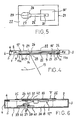
- edge flanges are dispensed with in the recess 7 ′ in the rear wall 2, and the game device 12 ′′ is fastened on the inside of a support plate 32, for example by gluing, the outside of which, in turn, is applied to the inside of a cardboard blank by means of an adhesive application 33 34 is glued.
- the cardboard blank 34 at the same time forms an outer cover of the recess 7 'by overlapping the recess 7' on the edge and glued to the rear wall 2 of the flat container in the edge regions thereof by means of adhesive applications 35.
- the cover 34 can also be plug-connected to the rear wall 2, for example with the aid of push-in tabs of the cover 34 which engage in insertion slots in the rear wall 2.
- the shaped film insert is indicated by dash-dotted lines in FIG. 6 at 36 and can be provided with an opening in the area of the interior 8 of the flat container adjacent to the recess 7 ', the edges of which surround the area of the container interior 8 adjacent to the recess 7'.
- This opening can be formed by a recess in the shaped film insert 36, which surrounds the area of the container interior 8 receiving the game device 12 ', taking into account the location of the game device 12' in the container, on two, three or all four sides.
- the game device 12 has a pressure switch 37 as a trigger mechanism, which is attached to the front wall 1 of the container.
- the pressure switch 37 is formed by a pressure plunger 38, the inner end of which is formed by a widened edge flange or head part 39.
- the pressure tappet 38 can be formed with its head part 39 by a one-piece molded plastic body.
- a holding and guiding disc 40 with a through opening 41 is glued, which is connected to a congruent opening in the front wall 1.
- the pressure plunger 38 rests with its edge flange 39 on the inside of the disk 40, as shown in FIG. 6.
- the user presses the pressure plunger 38 protruding through the opening 41 from the front wall, as a result of which the head part 39 is moved against a contact arm 42 and, as the movement continues inward, presses it against a contact part 42 of the electronic unit of the gaming device 12 "
- the predetermined melody is played even when the contact of the contact arm 42 with the contact part 43 is interrupted again by releasing the pressure plunger 38.
- the exemplary embodiment according to FIG. 6 corresponds to the other exemplary embodiments, as is expressed by the use of the same reference numerals for identical or matching parts. It goes without saying that the mutual distance between adjacent or bonded layers or parts of the container is drawn exaggerated in the interest of a clear representation.
Landscapes
- Engineering & Computer Science (AREA)
- Mechanical Engineering (AREA)
- Physics & Mathematics (AREA)
- General Physics & Mathematics (AREA)
- Theoretical Computer Science (AREA)
- Cartons (AREA)
- Packaging Frangible Articles (AREA)
- Confectionery (AREA)
Claims (8)
Priority Applications (3)
| Application Number | Priority Date | Filing Date | Title |
|---|---|---|---|
| AT86109567T ATE56680T1 (de) | 1986-07-12 | 1986-07-12 | Flachbehaelter fuer suesswaren, insbesondere wandkalender. |
| EP86109567A EP0253003B1 (fr) | 1986-07-12 | 1986-07-12 | Récipient de forme plate pour confiseries, en particulier calendrier d'Avent |
| DE8686109567T DE3674405D1 (de) | 1986-07-12 | 1986-07-12 | Flachbehaelter fuer suesswaren, insbesondere wandkalender. |
Applications Claiming Priority (1)
| Application Number | Priority Date | Filing Date | Title |
|---|---|---|---|
| EP86109567A EP0253003B1 (fr) | 1986-07-12 | 1986-07-12 | Récipient de forme plate pour confiseries, en particulier calendrier d'Avent |
Publications (2)
| Publication Number | Publication Date |
|---|---|
| EP0253003A1 EP0253003A1 (fr) | 1988-01-20 |
| EP0253003B1 true EP0253003B1 (fr) | 1990-09-19 |
Family
ID=8195265
Family Applications (1)
| Application Number | Title | Priority Date | Filing Date |
|---|---|---|---|
| EP86109567A Expired - Lifetime EP0253003B1 (fr) | 1986-07-12 | 1986-07-12 | Récipient de forme plate pour confiseries, en particulier calendrier d'Avent |
Country Status (3)
| Country | Link |
|---|---|
| EP (1) | EP0253003B1 (fr) |
| AT (1) | ATE56680T1 (fr) |
| DE (1) | DE3674405D1 (fr) |
Families Citing this family (5)
| Publication number | Priority date | Publication date | Assignee | Title |
|---|---|---|---|---|
| GB9102325D0 (en) * | 1991-02-02 | 1991-03-20 | Dextro North Limited | Novelty device |
| FR2717158B1 (fr) * | 1994-03-08 | 1996-08-23 | Sica Duprez | Boîte d'emballage d'articles, destinée notamment au conditionnement de friandises telles que chocolats. |
| WO2005091236A1 (fr) * | 2004-03-16 | 2005-09-29 | John Philip Griffits | Cave a vin automatisee |
| DE602006003404D1 (de) | 2006-01-16 | 2008-12-11 | Fine Tune Internat Ltd | Kalender Multimediagerät |
| US20130240387A1 (en) * | 2012-03-15 | 2013-09-19 | Chewters Chocolates | Presentation Box for Chocolates or other Consumables |
Family Cites Families (7)
| Publication number | Priority date | Publication date | Assignee | Title |
|---|---|---|---|---|
| BE484161A (fr) * | ||||
| DE2813540A1 (de) * | 1978-03-29 | 1979-10-04 | Kneisl Schokoladen Gmbh & Co K | Schachtel fuer schokolade |
| US4180165A (en) * | 1978-04-20 | 1979-12-25 | American Can Company | Blister package |
| US4222188A (en) * | 1978-09-22 | 1980-09-16 | Tarrant Fred A | Combined merchandise display, sound reproduction device and insignia supporting unit |
| DE3239597A1 (de) * | 1982-10-26 | 1984-04-26 | Marco Polo Industries & Merchandising Co., Ltd., Kowloon | Toenende postkarte |
| CH661022A5 (de) * | 1984-09-12 | 1987-06-30 | Andi Steiner | Verpackung fuer ein gut sowie behaeltnis. |
| DE8512998U1 (de) | 1985-05-03 | 1985-07-25 | Alfred Windel GmbH, 4500 Osnabrück | Verpackungsbehältnis für Süßwaren |
-
1986
- 1986-07-12 AT AT86109567T patent/ATE56680T1/de active
- 1986-07-12 EP EP86109567A patent/EP0253003B1/fr not_active Expired - Lifetime
- 1986-07-12 DE DE8686109567T patent/DE3674405D1/de not_active Expired - Lifetime
Also Published As
| Publication number | Publication date |
|---|---|
| ATE56680T1 (de) | 1990-10-15 |
| DE3674405D1 (de) | 1990-10-25 |
| EP0253003A1 (fr) | 1988-01-20 |
Similar Documents
| Publication | Publication Date | Title |
|---|---|---|
| EP0556628B1 (fr) | Emballage, notamment paquet du type souple pour cigarettes | |
| DE2822968C2 (de) | Steckverbindung zum Anschluß einer Programmierkassette an ein Fernsehspielgerät | |
| DE69814671T2 (de) | Behälter für nahrungsmittel | |
| DE69210958T2 (de) | Zigarettenpackungen | |
| DE69501267T2 (de) | Zuschnitt zur Herstellung einer leicht zu öffnenden amerikanischen Schachtel, sowie so hergestellte Schachtel | |
| DE60313651T2 (de) | Magazinbeilage mit einem fach für ein aufzeichnungsmedium | |
| DE2362427B2 (de) | Zuschnitt fuer eine fuer zigaretten oder zigarillos bestimmte schachtel | |
| CH661022A5 (de) | Verpackung fuer ein gut sowie behaeltnis. | |
| EP0745956A2 (fr) | Procédé de réalisation d'objets en plastique et produit semi-fini à utiliser dans ce procédé | |
| DE29715337U1 (de) | Tasteneinheit | |
| DE1586737A1 (de) | Faltschachtel fuer eine Farbband- oder aehnliche Kassette | |
| EP0253003B1 (fr) | Récipient de forme plate pour confiseries, en particulier calendrier d'Avent | |
| DE2837609C2 (de) | Behälter für eine Magnetbandkassette | |
| DE69302143T2 (de) | Dosenartige Verpackung mit Ausgabeöffnung | |
| DE8618941U1 (de) | Flachbehälter für Süßwaren, insbesondere Wandkalender | |
| EP3243760B1 (fr) | Emballage et section destinée à la fabrication d'un emballage | |
| DE8620939U1 (de) | Flachbehälter für Süßwaren, insbesondere Wandkalender | |
| DE3015748A1 (de) | Magnetbandkassettenbehaelter | |
| DE4103018C2 (de) | Halterung für einen zu verpackenden Gegenstand | |
| DE9405887U1 (de) | Kreditkartenbehältnis | |
| EP0115580A2 (fr) | Empaquetage pour matériaux de suture chirurgicales | |
| EP0703160A1 (fr) | Boîte à couvercle articulé pour cigarettes ou similaire | |
| DE69812940T2 (de) | Behälter | |
| DE29614075U1 (de) | Hartschachtel für Zigaretten mit Zündstreifen | |
| DE8512998U1 (de) | Verpackungsbehältnis für Süßwaren |
Legal Events
| Date | Code | Title | Description |
|---|---|---|---|
| PUAI | Public reference made under article 153(3) epc to a published international application that has entered the european phase |
Free format text: ORIGINAL CODE: 0009012 |
|
| AK | Designated contracting states |
Kind code of ref document: A1 Designated state(s): AT BE CH DE FR GB IT LI LU NL SE |
|
| RBV | Designated contracting states (corrected) |
Designated state(s): AT CH DE FR GB IT LI |
|
| 17P | Request for examination filed |
Effective date: 19880311 |
|
| 17Q | First examination report despatched |
Effective date: 19890404 |
|
| GRAA | (expected) grant |
Free format text: ORIGINAL CODE: 0009210 |
|
| AK | Designated contracting states |
Kind code of ref document: B1 Designated state(s): AT CH DE FR GB IT LI |
|
| REF | Corresponds to: |
Ref document number: 56680 Country of ref document: AT Date of ref document: 19901015 Kind code of ref document: T |
|
| ET | Fr: translation filed | ||
| ITF | It: translation for a ep patent filed | ||
| REF | Corresponds to: |
Ref document number: 3674405 Country of ref document: DE Date of ref document: 19901025 |
|
| GBT | Gb: translation of ep patent filed (gb section 77(6)(a)/1977) | ||
| PLBE | No opposition filed within time limit |
Free format text: ORIGINAL CODE: 0009261 |
|
| STAA | Information on the status of an ep patent application or granted ep patent |
Free format text: STATUS: NO OPPOSITION FILED WITHIN TIME LIMIT |
|
| ITTA | It: last paid annual fee | ||
| 26N | No opposition filed | ||
| PGFP | Annual fee paid to national office [announced via postgrant information from national office to epo] |
Ref country code: CH Payment date: 19930705 Year of fee payment: 8 |
|
| PG25 | Lapsed in a contracting state [announced via postgrant information from national office to epo] |
Ref country code: LI Effective date: 19940731 Ref country code: CH Effective date: 19940731 |
|
| REG | Reference to a national code |
Ref country code: CH Ref legal event code: PL |
|
| PGFP | Annual fee paid to national office [announced via postgrant information from national office to epo] |
Ref country code: AT Payment date: 19970728 Year of fee payment: 12 |
|
| PG25 | Lapsed in a contracting state [announced via postgrant information from national office to epo] |
Ref country code: AT Free format text: LAPSE BECAUSE OF NON-PAYMENT OF DUE FEES Effective date: 19980712 |
|
| REG | Reference to a national code |
Ref country code: GB Ref legal event code: IF02 |
|
| PGFP | Annual fee paid to national office [announced via postgrant information from national office to epo] |
Ref country code: DE Payment date: 20050622 Year of fee payment: 20 |
|
| PGFP | Annual fee paid to national office [announced via postgrant information from national office to epo] |
Ref country code: GB Payment date: 20050628 Year of fee payment: 20 |
|
| PG25 | Lapsed in a contracting state [announced via postgrant information from national office to epo] |
Ref country code: IT Free format text: LAPSE BECAUSE OF NON-PAYMENT OF DUE FEES;WARNING: LAPSES OF ITALIAN PATENTS WITH EFFECTIVE DATE BEFORE 2007 MAY HAVE OCCURRED AT ANY TIME BEFORE 2007. THE CORRECT EFFECTIVE DATE MAY BE DIFFERENT FROM THE ONE RECORDED. Effective date: 20050712 |
|
| PGFP | Annual fee paid to national office [announced via postgrant information from national office to epo] |
Ref country code: FR Payment date: 20050728 Year of fee payment: 20 |
|
| REG | Reference to a national code |
Ref country code: GB Ref legal event code: PE20 |
|
| PG25 | Lapsed in a contracting state [announced via postgrant information from national office to epo] |
Ref country code: GB Free format text: LAPSE BECAUSE OF EXPIRATION OF PROTECTION Effective date: 20060711 |