EP0253003A1 - Flachbehälter für Süsswaren, insbesondere Wandkalender - Google Patents
Flachbehälter für Süsswaren, insbesondere Wandkalender Download PDFInfo
- Publication number
- EP0253003A1 EP0253003A1 EP86109567A EP86109567A EP0253003A1 EP 0253003 A1 EP0253003 A1 EP 0253003A1 EP 86109567 A EP86109567 A EP 86109567A EP 86109567 A EP86109567 A EP 86109567A EP 0253003 A1 EP0253003 A1 EP 0253003A1
- Authority
- EP
- European Patent Office
- Prior art keywords
- container
- recess
- container according
- flat
- flap
- Prior art date
- Legal status (The legal status is an assumption and is not a legal conclusion. Google has not performed a legal analysis and makes no representation as to the accuracy of the status listed.)
- Granted
Links
Images

Classifications
-
- B—PERFORMING OPERATIONS; TRANSPORTING
- B65—CONVEYING; PACKING; STORING; HANDLING THIN OR FILAMENTARY MATERIAL
- B65D—CONTAINERS FOR STORAGE OR TRANSPORT OF ARTICLES OR MATERIALS, e.g. BAGS, BARRELS, BOTTLES, BOXES, CANS, CARTONS, CRATES, DRUMS, JARS, TANKS, HOPPERS, FORWARDING CONTAINERS; ACCESSORIES, CLOSURES, OR FITTINGS THEREFOR; PACKAGING ELEMENTS; PACKAGES
- B65D5/00—Rigid or semi-rigid containers of polygonal cross-section, e.g. boxes, cartons or trays, formed by folding or erecting one or more blanks made of paper
- B65D5/42—Details of containers or of foldable or erectable container blanks
- B65D5/4291—Containers provided with an acoustic device, e.g. for indicating opening of the package
-
- B—PERFORMING OPERATIONS; TRANSPORTING
- B65—CONVEYING; PACKING; STORING; HANDLING THIN OR FILAMENTARY MATERIAL
- B65D—CONTAINERS FOR STORAGE OR TRANSPORT OF ARTICLES OR MATERIALS, e.g. BAGS, BARRELS, BOTTLES, BOXES, CANS, CARTONS, CRATES, DRUMS, JARS, TANKS, HOPPERS, FORWARDING CONTAINERS; ACCESSORIES, CLOSURES, OR FITTINGS THEREFOR; PACKAGING ELEMENTS; PACKAGES
- B65D85/00—Containers, packaging elements or packages, specially adapted for particular articles or materials
- B65D85/60—Containers, packaging elements or packages, specially adapted for particular articles or materials for sweets or like confectionery products
-
- G—PHYSICS
- G09—EDUCATION; CRYPTOGRAPHY; DISPLAY; ADVERTISING; SEALS
- G09D—RAILWAY OR LIKE TIME OR FARE TABLES; PERPETUAL CALENDARS
- G09D3/00—Perpetual calendars
Definitions
- the invention relates to a flat container for confectionery, in particular a wall calendar, according to the preamble of claim 1.
- Such flat containers or wall calendars for confectionery have found widespread use particularly as advent calendars.
- the known advent calendars are provided in their front wall with 24 flaps or small doors, each of which can be folded along a fold line so that the confectionery located behind it in the respective recess of the shaped film insert can be removed.
- the outside of their front wall is usually designed as a picture with Christmas motifs in particular.
- the invention has for its object to increase the gift value of flat containers for confectionery of the specified type with simple means.
- the flat container can in particular be designed as a folding box, the Cardboard blank that provides the one-piece flap forming the rear wall.
- the recess in the one-piece flap can be produced by a simple punching process in the flat state of the cardboard blank in order to form an access opening to the interior of the container in the state of the cardboard blank which is folded together and glued together along a longitudinal side edge and which contains a play device in the region of the recess .
- This game device which is provided in addition to the sweets in the container, increases the gift value in particular of a correspondingly designed advent calendar and offers an additional incentive to buy.
- the game device can take into account the play instinct of children and can be designed, for example, as a music box or as an electronic music game machine.
- These well-known music slot machines comprise a thin, platelike music chip as well as battery and loudspeaker and a suitable trigger mechanism, when actuated a melody sounds, in the case of using the flat container as an advent calendar a Christmas or advent song.
- the flat container shown in the drawing is designed as a flat wall calendar, in particular as an advent calendar, and is formed from a one-piece cardboard blank in the manner of a folding box, in the interior of which a molded film insert with recesses accommodating confectionery is accommodated.
- the recesses are open towards the front of the container and are arranged behind flaps in the front of the container, which can be opened to remove the confectionery from the recesses in the molded film insert.
- the cardboard blank when folded and glued in the manner of a folding box, forms an outer shell for the use of shaped films with a front wall 1, a rear wall 2 and narrow side walls 3 and 4, all of which are in one piece, i.e. of the one-piece cardboard blank as a starting workpiece.
- the side wall 4 is provided with an inward longitudinal adhesive tab 5 and is glued here to the adjacent edge area of the rear wall 2 by means of an adhesive application 6.
- a recess 7 has been punched into the rear wall 2 in the flat state of the cardboard blank.
- This punching process can be carried out simultaneously with the punching process
- Front wall 1 of the container for attaching the flaps or small doors for removing the confectionery from the molded film insert can be carried out.
- the recess 7 creates an access opening to the interior 8 of the container and, according to the exemplary embodiment according to FIGS. 1 to 3, is provided with integrally molded edge flanges 9 of the surface shape which can be seen in particular in FIG. 2.
- the four edge flanges 9 of the rectangular recess are oriented approximately perpendicular to the front wall 1 and are provided at their ends adjoining the front wall with adhesive tabs 10 bent at right angles to the recess 7.
- the gluing approaches 10 are each limited to a central region of the edge flanges 9 and glued to the inside of the front wall 1 by means of an adhesive application 11 each.
- the edge flanges 9 of the recess 7 form a compartment delimited from the interior 8 of the container, in which a game device 12 is fixed by gluing, locking or in some other suitable manner.
- the game device 12 is fixed by gluing with the aid of adhesive orders 11a, which are arranged on the side of the bonding approaches 10 opposite the adhesive orders 11.
- a flap 13 is provided in the front wall 1 in the front wall 1 of the container opposite the recess 7 or the game device 12, which allows access to the game device 12.
- the flap 13 is punched out on three sides of the front wall 1 and articulated on the fourth side on the hinge side to form a fold line 14 on the front wall 1.
- the contour of the game device 12 corresponds to the recess 7 in the rear wall 2 of the container and closes on the back essentially flush with this.
- the game device 12 comprises a rear support in the form of a shaped plate 15, in which the electronic unit 16 of the game device 12 is fixed in an arrangement adjacent to the front wall 1.
- the assembly 16 comprises as a trigger mechanism a light-sensitive sensor 17, which is normally covered by the flap 13 in the front wall 1 and thus kept darkened.
- the flap 13 which is shown in FIG. 3 in the open position, is provided with a return spring which strives to Hold flap 13 in its closed position.
- the return spring is formed by a rubber band 18 that is attached to the flap 13 in the end region adjacent to the fold line 14, is guided through a channel 19 through the mold plate 15 to the rear of the rear wall 2 and is fixed there by means of a fastening tab 20.
- the game device 12 ⁇ comprises a cardboard blank 21 with a card-shaped lower part 22 and a card-shaped upper part 23, which have a rectangular contour corresponding to the recess 7 and are connected to one another by a fold line 24 at one of their edges.
- the lower part 22 and upper part 23 can be glued to one another on the other three sides.
- the lower support part 23 is glued to the four adhesive lugs 10 of the edge flanges 9 of the recess 7 by means of the adhesive layers 11a.
- the electronic assembly 16 ⁇ of the game device 12 ⁇ is on the inside of the Ab support lower part 22 fixed and covered by the upper support part 23 to the front wall flap 13.
- the electronic assembly 16 of the game device 12 is triggered by opening the front-side flap 13 and thus an exposure of the sensor 17 and, for example, a Christmas carol sounds with the help of the integrated music chip in the exemplary embodiment according to FIGS. 4 and 5, the triggering of the electronic unit by actuating the front wall flap 13.
- a pull tab 25 which for this purpose consists, for example, of an electrically non-conductive material, such as plastic, and in a manner not shown in detail Trigger contact of the electronic unit 16 ⁇ interrupts.
- the end 26 of the pull tab 25 facing away from the assembly 16 ⁇ is fixed in a suitable manner on the container in order to produce the triggering contact of the assembly 16 ⁇ when the front wall flap 13 is opened about the pivot axis defined by the fold line 14.
- the end 26 facing away from the structural unit 16 ⁇ is connected to the inside of the front wall flap 13 via a connecting strap 27, which is shown in FIG. 4 in the half-open position.
- the connecting tab 27 is punched out on three sides of the lower support part 22, passed through an opening 28 in the upper support part 23 and connected, for example glued, to the inside of the flap 13.
- the side of the connecting link 27 which is integrally connected to the lower support part 22 along a seam line 29 forms a hinge-like pivot axis in the vicinity of and parallel to the pivot axis the front panel flap 13, which is defined by the fold line 14.
- the pull tab 25 When the front wall flap 13 is opened in the direction of the arrow 30 in FIG. 4, the pull tab 25 is thus pulled forward in the longitudinal direction corresponding to the pivot axis 14, whereby it is guided by means of an opening 31 on the electronic unit 16 'by a (not shown) contact arm Unit 16 ⁇ reaches through the opening 31.
- the trigger contact of the electronic assembly 16 ⁇ is produced when, during the pulling movement of the pull tab 25 in accordance with the directional arrow 30, the contact arm with a contact area provided for this purpose comes into conductive connection with the assembly 16 ⁇ or a music chip integrated into it .
- the front wall flap 13 When the front wall flap 13 is opened, the front side of the upper support part 23 becomes visible, which for this reason can have a picture motif or another appealing surface design, which can also be provided in the configuration according to FIGS. 1 to 3.
- the trigger contact of the assembly 16 ⁇ is interrupted when the front flap 13 is closed against the arrow 21 again, when the correspondingly moved back contact tab 25 with its hole-free part is pushed under the contact area of the contact arm of the electronic assembly 16 ⁇ .
- edge flanges are dispensed with in the recess 7 ⁇ in the rear wall 2, and the game device 12 ⁇ is fastened on the inside of a support plate 32, for example by gluing, the outside of which in turn is glued to the inside of a cardboard blank 34 by means of an adhesive application 33 is.
- the cardboard blank 34 at the same time forms an outside cover of the recess 7 ⁇ by overlapping the recess 7 ⁇ on the edge and glued to the rear wall 2 of the flat container in the edge regions thereof by means of adhesive applications 35.
- the cover 34 can also be plug-connected to the rear wall 2, for example with the aid of push-in tabs of the cover 34 which engage in insertion slots in the rear wall 2.
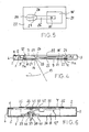
- the shaped film insert is indicated by dash-dotted lines in FIG. 6 at 36 and can be provided with an opening in the area of the interior 8 of the flat container adjacent to the recess 7 ⁇ , the edges of which surround the area of the container interior 8 adjacent to the recess 7 ⁇ .
- This opening can be formed by a recess in the shaped film insert 36, which surrounds the area of the container interior 8 receiving the game device 12 ⁇ , taking into account the mounting location of the game device 12 ⁇ in the container on two, three or all four sides.
- the game device 12 ⁇ has in the embodiment of FIG. 6 as a trigger mechanism, a pressure switch 37 which is attached to the front wall 1 of the container.
- the pressure switch 37 is formed by a pressure tappet 38, the inner end of which is occupied by a widened edge flange or head part 39.
- the pressure ram 38 can be formed with its head part 39 from a one-piece molded plastic body.
- a holding and guiding disc 40 with a through opening 41 is glued, which is connected to a congruent opening in the front wall 1.
- the pressure plunger 38 rests with its edge flange 39 on the inside of the disk 40, as shown in FIG. 6.
- the user presses on the pressure plunger 38 protruding through the opening 41 from the front wall, as a result of which the head part 39 is moved against a contact arm 42 and, as the movement continues inward, presses it against a contact part 42 of the electronic unit of the gaming device 12 '.
- the predetermined melody is also played to the end when the contact of the contact arm 42 with the contact part 43 is interrupted again by releasing the pressure plunger 38.
- the exemplary embodiment according to FIG. 6 corresponds to the other exemplary embodiments, as is expressed by the use of the same reference numerals for identical or matching parts. It goes without saying that the mutual distance between adjoining or bonded layers or parts of the container is exaggerated in the interest of a clear representation.
Landscapes
- Engineering & Computer Science (AREA)
- Mechanical Engineering (AREA)
- Physics & Mathematics (AREA)
- General Physics & Mathematics (AREA)
- Theoretical Computer Science (AREA)
- Cartons (AREA)
- Packaging Frangible Articles (AREA)
- Confectionery (AREA)
Abstract
Description
- Die Erfindung betrifft einen Flachbehälter für Süßwaren, insbesondere Wandkalender, nach dem Oberbegriff des Anspruchs 1.
- Derartige Flachbehälter bzw. Wandkalender für Süßwaren haben insbesondere als Adventskalender weite Verbreitung gefunden. Die bekannten Adventskalender sind in ihrer Vorderwand mit 24 Klappen bzw. kleinen Türchen versehen, die jeweils entlang einer Faltlinie aufklappbar sind, damit die dahinter in der jeweiligen Vertiefung des Formfolieneinsatzes befindlichen Süßwaren entnommen werden können. Da die Adventskalender zur Weihnachtszeit verschenkt werden, ist ihre Vorderwand außenseitig in der Regel als Bild mit insbesondere weihnachtlichen Motiven ausgeführt.
- Der Erfindung liegt die Aufgabe zugrunde, den Geschenkwert von Flachbehältern für Süßwaren der angegebenen Art mit einfachen Mitteln zu erhöhen.
- Diese Aufgabe wird nach der Erfindung durch eine Ausgestaltung des Flachbehälters gemäß dem Anspruch 1 gelöst. Bei dieser Ausgestaltung kann der Flachbehälter insbesondere als Faltschachtel ausgeführt sein, deren Pappzuschnitt die die Rückwand bildende einteilige Klappe darbietet. Die Ausnehmung in der einteiligen Klappe kann dabei durch einen einfachen Stanzvorgang im flachliegenden Zustand des Pappzuschnitts hergestellt werden, um im zum Flachbehälter zusammengefalteten und entlang einem Längsseitenrand zusammengeklebten Zustand des Pappzuschnitts eine Zugangsöffnung zum Innenraum des Behälters zu bilden, der im Bereich der Ausnehmung eine Spielvorrichtung enthält. Diese Spielvorrichtung, die zusätzlich zu den Süßwaren im Behälter vorgesehen ist, erhöht den Geschenkwert insbesondere eines entsprechend ausgestalteten Adventskalenders und bietet einen zusätzlichen Kaufanreiz. Die Spielvorrichtung kann dabei dem Spieltrieb von Kindern Rechnung tragen und beispielsweise als Spieluhr oder auch als elektronischer Musikspielautomat ausgeführt sein. Diese an sich bekannten Musikspielautomaten umfassen einen dünnen, plättchenförmigen Musik-Chip sowie Batterie und Lautsprecher und einen geeigneten Auslösemechanismus, bei dessen Betätigung eine Melodie, im Falle der Verwendung des Flachbehälters als Adventskalender ein Weihnachts- oder Adventslied, ertönt.
- Weitere Merkmale und Vorteile der Erfindung ergeben sich aus den Unteransprüchen und der nachstehenden Beschreibung in Verbindung mit der Zeichnung, in der mehrere Ausführungsbeispiele des Gegenstands der Erfindung schematisch veranschaulicht sind. In der Zeichnung zeigen:
- Fig. 1 eine Draufsicht auf die Rückwand eines Flachbehälters für Süßwaren in Form einer Faltschachtel,
- Fig. 2 einen Schnitt nach der Linie II-II der Fig. 1,
- Fig. 3 eine Schnittdarstellung entsprechend Fig. 2 mit eingesetzter Spielvorrichtung,
- Fig. 4 eine Schnittdarstellung entsprechend Fig. 3 mit einer abgewandelten Ausführungsform der Spielvorrichtung,
- Fig. 5 einen Schnitt durch die Spielvorrichtung nach Fig. 4 entlang der Linie V-V und
- Fig. 6 eine weitere Schnittdarstellung entsprechend den Fig. 3 und 4 zur Veranschaulichung weiterer Abwandlungen.
- Der in der Zeichnung dargestellte Flachbehälter ist als flacher Wandkalender, insbesondere als Adventskalender ausgeführt und von einem einteiligen Pappzuschnitt nach Art einer Faltschachtel gebildet, in deren Innenraum ein Formfolieneinsatz mit Süßwaren aufnehmenden Vertiefungen untergebracht ist. Die Vertiefungen sind zur Behältervorderseite hin offen und hinter Klappen in der Behältervorderseite angeordnet, die zur Herausnahme der Süßwaren aus den Vertiefungen des Formfolieneinsatzes geöffnet werden können.
- Der Pappzuschnitt bildet in seinem faltschachtelartig zusammengefalteten und verklebten Zustand eine Außenhülle für den Formfolieneinsatz mit einer Vorderwand 1, einer Rückwand 2 und schmalen Seitenwänden 3 und 4, die sämtlich einteilig, d.h. von dem einteiligen Pappzuschnitt als Ausgangswerkstück, ausgeführt sind. Dabei ist die Seitenwand 4 mit einer einwärts gerichteten längslaufenden Klebelasche 5 versehen und hier mittels eines Klebstoffauftrags 6 mit dem angrenzenden Randbereich der Rückwand 2 verklebt.
- Bevor der Pappzuschnitt zur Faltschachtel mit der aus Fig. 2 ersichtlichen Querschnittsform geformt ist, ist im flachliegenden Zustand des Pappzuschnitts eine Ausnehmung 7 in die Rückwand 2 gestanzt worden. Dieser Stanzvorgang kann gleichzeitig mit der Stanzbearbeitung der Vorderwand 1 des Behälters zum Anbringen der Klappen bzw. kleinen Türchen zur Herausnahme der Süßwaren aus dem Formfolieneinsatz durchgeführt werden. Die Ausnehmung 7 schafft eine Zugangsöffnung zum Innenraum 8 des Behälters und ist gemäß dem Ausführungsbeispiel nach den Fig. 1 bis 3 mit einstückig angeformten Randflanschen 9 der insbesondere aus Fig. 2 ersichtlichen Flächenform versehen. Die vier Randflansche 9 der rechteckig ausgeführten Ausnehmung sind etwa senkrecht zur Vorderwand 1 ausgerichtet und an ihren an die Vorderwand angrenzenden Enden mit rechtwinklig zur Ausnehmung 7 hin abgebogenen Verklebungsansätzen 10 versehen. Die Verklebungsansätze 10 sind, wie dies insbesondere aus Fig. 1 ersichtlich ist, jeweils auf einen mittleren Bereich der Randflansche 9 beschränkt und mittels je eines Klebstoffauftrags 11 mit der Innenseite der Vorderwand 1 verklebt.
- Die Randflansche 9 der Ausnehmung 7 bilden ein vom Innenraum 8 des Behälters abgegrenztes Abteil, in dem eine Spielvorrichtung 12 durch Verklebung, Verriegelung oder in sonst geeigneter Weise festgelegt ist. Bei dem Ausführungsbeispiel nach den Fig. 1 bis 3 ist die Festlegung der Spielvorrichtung 12 durch Verklebung mit Hilfe von Klebstoffaufträgen 11a vorgenommen, die auf der den Klebstoffaufträgen 11 gegenüberliegenden Seite der Verklebungsansätze 10 angeordnet sind. Dabei ist in der Vorderwand 1 des Behälters in Gegenüberlage der Ausnehmung 7 bzw. der Spielvorrichtung 12 eine Klappe 13 in der Vorderwand 1 vorgesehen, die einen Zugang zur Spielvorrichtung 12 ermöglicht. Die Klappe 13 ist dreiseitig aus der Vorderwand 1 ausgestanzt und an ihrer vierten Seite scharnierseitig unter Ausbildung einer Falzlinie 14 an die Vorderwand 1 angelenkt.
- Die Kontur der Spielvorrichtung 12 entspricht der Ausnehmung 7 in der Rückwand 2 des Behälters und schließt rückseitig im wesentlichen bündig mit dieser ab. Dabei umfaßt die Spielvorrichtung 12 eine rückseitige Abstützung in Gestalt einer Formplatte 15, in der die elektronische Baueinheit 16 der Spielvorrichtung 12 in einer an die Vorderwand 1 angrenzenden Anordnung festgelegt ist. Die Baueinheit 16 umfaßt dabei als Auslösemechanismus einen lichtempfindlichen Sensor 17, der normalerweise von der Klappe 13 in der Vorderwand 1 abgedeckt und damit verdunkelt gehalten ist.
- Damit die Verdunkelung des Sensors 17 im Nichtgebrauch der Spielvorrichtung 12 durch eine satte Anlage der Klappe 13 auch bei häufigerer Benutzung gewährleistet bleibt, ist die Klappe 13, die in Fig. 3 in Offenstellung gezeigt ist, mit einer Rückstellfeder versehen, die bestrebt ist, die Klappe 13 in ihrer Schließstellung zu halten. Bei dem dargestellten Beispiel ist die Rückstellfeder von einem Gummiband 18 gebildet, daß im an die Falzlinie 14 angrenzenden Endbereich an der Klappe 13 befestigt, durch einen Kanal 19 durch die Formplatte 15 zur Rückseite der Rückwand 2 geführt und dort mittels einer Befestigungslasche 20 festgelegt ist.
- Bei dem Ausführungsbeispiel nach den Fig. 4 und 5 umfaßt die Spielvorrichtung 12ʹ einen Kartonzuschnitt 21 mit einem kartenförmigen Unterteil 22 und einem kartenförmigen Oberteil 23, die eine der Ausnehmung 7 entsprechende rechteckige Kontur aufweisen und an einem ihrer Ränder durch eine Falzlinie 24 miteinander verbunden sind. An den drei übrigen Seiten können Unterteil 22 und Oberteil 23 randseitig miteinander verklebt sein. Zur Festlegung der Spielvorrichtung 12ʹ in der Ausnehmung 7 ist der Abstützungsunterteil 23 mittels der Klebstoffaufträge 11a mit den vier Verklebungsansätzen 10 der Randflansche 9 der Ausnehmung 7 verklebt. Die elektronische Baueinheit 16ʹ der Spielvorrichtung 12ʹ ist auf der Innenseite des Ab stützungsunterteils 22 festgelegt und vom Abstützungsoberteil 23 zur vorderwandseitigen Klappe 13 hin abgedeckt.
- Ebenso wie bei dem Ausführungsbeispiel nach den Fig. 1 bis 3 die elektronische Baueinheit 16 der Spielvorrichtung 12 durch ein Öffnen der vorderwandseitigen Klappe 13 und damit eine Belichtung des Sensors 17 ausgelöst wird und beispielsweise ein Weihnachtslied mit Hilfe des integrierten Musik-Chips ertönt, erfolgt auch bei dem Ausführungsbeispiel gemäß den Fig. 4 und 5 die Auslösung der elektronischen Baueinheit durch Betätigung der Vorderwandklappe 13.
- In der normalerweise von der Vorderwandklappe 13 eingenommenen Schließstellung ist das Spielen der Spielvorrichtung 12ʹ bzw. der elektronischen Baueinheit 16ʹ mit Hilfe einer Zuglasche 25 unterbunden, die zu diesem Zweck beispielsweise aus einem elektrisch nichtleitenden Material, wie Kunststoff, besteht und in nicht näher dargestellter Weise einen Auslösekontakt der elektronischen Baueinheit 16ʹ unterbricht. Das von der Baueinheit 16ʹ abgewandte Ende 26 der Zuglasche 25 ist in geeigneter Weise am Behälter festgelegt, um den Auslösekontakt der Baueinheit 16ʹ beim Aufklappen der Vorderwandklappe 13 um die von der Falzlinie 14 definierte Schwenkachse herzustellen.
- Hierzu ist das von der Baueinheit 16ʹ abgewandte Ende 26 über eine Verbindungslasche 27 mit der Innenseite der Vorderwandklappe 13 verbunden, die in Fig. 4 in halb geöffneter Stellung gezeigt ist. Die Verbindungslasche 27 ist dreiseitig aus dem Abstützungsunterteil 22 ausgestanzt, durch eine Öffnung 28 im Abstützungsoberteil 23 hindurchgeführt und mit der Innenseite der Klappe 13 verbunden, z.B. verklebt. Die mit dem Abstützungsunterteil 22 einstückig entlang einer Flazlinie 29 verbundene Seite der Verbindungslasche 27 bildet dabei eine scharnierartige Schwenkachse in der Nähe der und parallel zur Schwenkachse der Vorderwandklappe 13, die von der Falzlinie 14 definiert ist.
- Beim Aufklappen der Vorderwandklappe 13 in Richtung des Pfeils 30 in Fig. 4 wird somit die Zuglasche 25 in Längsrichtung entsprechend zur Schwenkachse 14 hin vorgezogen, wobei sie mittels einer Öffnung 31 an der elektronischen Baueinheit 16ʹ geführt ist, indem ein (nicht dargestellter) Kontaktarm der Baueinheit 16ʹ die Öffnung 31 durchgreift. Dabei wird der Auslösekontakt der elektronischen Baueinheit 16ʹ hergestellt, wenn während der Vorziehbewegung der Zuglasche 25 entsprechend dem Richtungspfeil 30 der Kontaktarm mit einem hierfür vorgesehenen Kontaktbereich durch die Öffnung 31 hindurch in leitende Verbindung mit der Baueinheit 16ʹ bzw. einem in diese integrierten Musik-Chip gelangt.
- Mit dem Aufklappen der Vorderwandklappe 13 wird die Vorderseite des Abstützungsoberteils 23 sichtbar, die aus diesem Grunde ein Bildmotiv oder eine sonstige ansprechende Oberflächengestaltung aufweisen kann, die im übrigen auch bei der Ausgestaltung gemäß den Fig. 1 bis 3 vorgesehen sein kann. Der Auslösekontakt der Baueinheit 16ʹ wird beim Zuklappen der Vorderwandklappe 13 entgegen dem Pfeil 21 wieder unterbrochen, wenn sich die dabei entsprechend zurückbewegte Kontaktlasche 25 mit ihrem lochfreien Teil unter den Kontaktbereich des Kontaktarms der elektronischen Baueiheit 16ʹ schiebt.
- Bei dem Ausführungsbeispiel gemäß Fig. 6 ist bei der Ausnehmung 7ʹ in der Rückwand 2 auf Randflansche verzichtet, und die Spielvorrichtung 12ʺ ist auf der Innenseite einer Tragplatte 32 z.B. durch Verklebung befestigt, deren Außenseite ihrerseits mittels eines Klebstoffauftrags 33 mit der Innenseite eines Kartonzuschnitts 34 verklebt ist.
- Der Kartonzuschnitt 34 bildet zugleich eine außenseitige Abdeckung der Ausnehmung 7ʹ, indem er die Ausnehmung 7ʹ randseitig übergreift und in deren Randbereichen mittels Klebstoffaufträgen 35 mit der Rückwand 2 des Flachbehälters verklebt ist. Anstelle einer solchen Verklebung kann auch eine Steckverbindung der Abdeckung 34 mit der Rückwand 2 beispielsweise mit Hilfe von in Einsteckschlitze der Rückwand 2 eingreifenden Einstecklaschen der Abdeckung 34 vorgenommen sein.
- Der Formfolieneinsatz ist in Fig. 6 bei 36 strichpunktiert angedeutet und kann im an die Ausnehmung 7ʹ angrenzenden Bereich des Innenraums 8 des Flachbehälters mit einer Öffnung versehen sein, deren Ränder den an die Ausnehmung 7ʹ angrenzenden Bereich des Behälterinnenraums 8 umgeben. Diese Öffnung kann von einer Aussparung im Formfolieneinsatz 36 gebildet sein, die den die Spielvorrichtung 12ʹ aufnehmenden Bereich des Behälterinnenraums 8 unter Berücksichtigung des Anbringungsorts der Spielvorrichtung 12ʹ im Behälter an zwei, drei oder allen vier Seiten abstützend umgibt.
- Die Spielvorrichtung 12ʺ weist bei dem Ausführungsbeispiel nach Fig. 6 als Auslösemechanismus einen Druckschalter 37 auf, der an der Vorderwand 1 des Behälters angebracht ist. Der Druckschalter 37 ist gemäß dem dargestellten Beispiel von einem Druckstößel 38 gebildet, dessen inneres Ende von einem verbreiterten Randflansch bzw. Kopfteil 39 eingenommen ist. Der Druckstößel 38 kann dabei mit seinem Kopfteil 39 von einem einteiligen Kunststofformkörper gebildet sein.
- Auf die Innenseite der Vorderwand 1 des Behälters ist eine Halte- und Führungsscheibe 40 mit einer Durchgangsöffnung 41 aufgeklebt, die mit einer deckungsgleichen Öffnung in der Vorderwand 1 in Verbindung steht. In seiner Ruhestellung liegt der Druckstößel 38 mit seinem Randflansch 39 an der Innenseite der Scheibe 40 an, wie es in Fig. 6 gezeigt ist.
- Zur Betätigung des Druckschalters 37 drückt der Benutzer auf den durch die Öffnung 41 aus der Vorderwand herausragenden Druckstößel 38, wodurch dieser mit seinem Kopfteil 39 gegen einen Kontaktarm 42 bewegt wird und diesen bei fortgesetzter Einwärtsbewegung gegen ein Kontaktteil 42 der elektronischen Baueinheit der Spielvorrichtung 12ʺ drückt. Hierdurch wird die Spielvorrichtung ausgelöst und eine in den Musik-Chip der elektronischen Baueinheit eingegebene Melodie ertönt. Die vorgegebene Melodie wird auch dann zuende gespielt, wenn durch Loslassen des Druckstößels 38 der Kontakt des Kontaktarms 42 mit dem Kontaktteil 43 wieder unterbrochen wird.
- Hinsichtlich der Ausbildung des Flachbehälters nach Art einer Faltschachtel stimmt das Ausführungsbeispiel nach Fig. 6 mit den übrigen Ausführungsbeispielen überein, wie es durch die Verwendung gleicher Bezugszeichen für gleiche bzw. übereinstimmende Teile zum Ausdruck gebracht ist. Es versteht sich im übrigen, daß der gegenseitige Abstand zwischen aneinandergrenzenden bzw. miteinander verklebten Lagen bzw. Teilen des Behälters im Interesse einer deutlichen Darstellung übertrieben groß gezeichnet ist.
Claims (14)
Priority Applications (3)
| Application Number | Priority Date | Filing Date | Title |
|---|---|---|---|
| AT86109567T ATE56680T1 (de) | 1986-07-12 | 1986-07-12 | Flachbehaelter fuer suesswaren, insbesondere wandkalender. |
| EP86109567A EP0253003B1 (de) | 1986-07-12 | 1986-07-12 | Flachbehälter für Süsswaren, insbesondere Wandkalender |
| DE8686109567T DE3674405D1 (de) | 1986-07-12 | 1986-07-12 | Flachbehaelter fuer suesswaren, insbesondere wandkalender. |
Applications Claiming Priority (1)
| Application Number | Priority Date | Filing Date | Title |
|---|---|---|---|
| EP86109567A EP0253003B1 (de) | 1986-07-12 | 1986-07-12 | Flachbehälter für Süsswaren, insbesondere Wandkalender |
Publications (2)
| Publication Number | Publication Date |
|---|---|
| EP0253003A1 true EP0253003A1 (de) | 1988-01-20 |
| EP0253003B1 EP0253003B1 (de) | 1990-09-19 |
Family
ID=8195265
Family Applications (1)
| Application Number | Title | Priority Date | Filing Date |
|---|---|---|---|
| EP86109567A Expired - Lifetime EP0253003B1 (de) | 1986-07-12 | 1986-07-12 | Flachbehälter für Süsswaren, insbesondere Wandkalender |
Country Status (3)
| Country | Link |
|---|---|
| EP (1) | EP0253003B1 (de) |
| AT (1) | ATE56680T1 (de) |
| DE (1) | DE3674405D1 (de) |
Cited By (5)
| Publication number | Priority date | Publication date | Assignee | Title |
|---|---|---|---|---|
| WO1992013770A1 (en) * | 1991-02-02 | 1992-08-20 | Fine Art Developments Plc | Novelty devices |
| FR2717158A1 (fr) * | 1994-03-08 | 1995-09-15 | Sica Duprez | Boîte d'emballage d'articles, destinée notamment au conditionnement de friandises telles que chocolats. |
| EP1808839A1 (de) | 2006-01-16 | 2007-07-18 | Fine Tune International Ltd. | Kalender Multimediagerät |
| GB2449002B (en) * | 2004-03-16 | 2008-12-31 | John Philip Griffits | Computerised confectionery container |
| WO2013134859A1 (en) * | 2012-03-15 | 2013-09-19 | Chewters Chocolates | Presentation box for chocolates or other consumables |
Citations (7)
| Publication number | Priority date | Publication date | Assignee | Title |
|---|---|---|---|---|
| BE484161A (de) * | ||||
| DE2813540A1 (de) * | 1978-03-29 | 1979-10-04 | Kneisl Schokoladen Gmbh & Co K | Schachtel fuer schokolade |
| US4180165A (en) * | 1978-04-20 | 1979-12-25 | American Can Company | Blister package |
| US4222188A (en) * | 1978-09-22 | 1980-09-16 | Tarrant Fred A | Combined merchandise display, sound reproduction device and insignia supporting unit |
| DE3239597A1 (de) * | 1982-10-26 | 1984-04-26 | Marco Polo Industries & Merchandising Co., Ltd., Kowloon | Toenende postkarte |
| DE8512998U1 (de) | 1985-05-03 | 1985-07-25 | Alfred Windel GmbH, 4500 Osnabrück | Verpackungsbehältnis für Süßwaren |
| EP0174913A2 (de) * | 1984-09-12 | 1986-03-19 | Andi Steiner | Verpackung für ein Gut, sowie Verwendung derselben |
-
1986
- 1986-07-12 AT AT86109567T patent/ATE56680T1/de active
- 1986-07-12 EP EP86109567A patent/EP0253003B1/de not_active Expired - Lifetime
- 1986-07-12 DE DE8686109567T patent/DE3674405D1/de not_active Expired - Lifetime
Patent Citations (7)
| Publication number | Priority date | Publication date | Assignee | Title |
|---|---|---|---|---|
| BE484161A (de) * | ||||
| DE2813540A1 (de) * | 1978-03-29 | 1979-10-04 | Kneisl Schokoladen Gmbh & Co K | Schachtel fuer schokolade |
| US4180165A (en) * | 1978-04-20 | 1979-12-25 | American Can Company | Blister package |
| US4222188A (en) * | 1978-09-22 | 1980-09-16 | Tarrant Fred A | Combined merchandise display, sound reproduction device and insignia supporting unit |
| DE3239597A1 (de) * | 1982-10-26 | 1984-04-26 | Marco Polo Industries & Merchandising Co., Ltd., Kowloon | Toenende postkarte |
| EP0174913A2 (de) * | 1984-09-12 | 1986-03-19 | Andi Steiner | Verpackung für ein Gut, sowie Verwendung derselben |
| DE8512998U1 (de) | 1985-05-03 | 1985-07-25 | Alfred Windel GmbH, 4500 Osnabrück | Verpackungsbehältnis für Süßwaren |
Cited By (6)
| Publication number | Priority date | Publication date | Assignee | Title |
|---|---|---|---|---|
| WO1992013770A1 (en) * | 1991-02-02 | 1992-08-20 | Fine Art Developments Plc | Novelty devices |
| US5435787A (en) * | 1991-02-02 | 1995-07-25 | Fine Art Developments Plc | Devices |
| FR2717158A1 (fr) * | 1994-03-08 | 1995-09-15 | Sica Duprez | Boîte d'emballage d'articles, destinée notamment au conditionnement de friandises telles que chocolats. |
| GB2449002B (en) * | 2004-03-16 | 2008-12-31 | John Philip Griffits | Computerised confectionery container |
| EP1808839A1 (de) | 2006-01-16 | 2007-07-18 | Fine Tune International Ltd. | Kalender Multimediagerät |
| WO2013134859A1 (en) * | 2012-03-15 | 2013-09-19 | Chewters Chocolates | Presentation box for chocolates or other consumables |
Also Published As
| Publication number | Publication date |
|---|---|
| ATE56680T1 (de) | 1990-10-15 |
| DE3674405D1 (de) | 1990-10-25 |
| EP0253003B1 (de) | 1990-09-19 |
Similar Documents
| Publication | Publication Date | Title |
|---|---|---|
| EP0556628B1 (de) | Verpackung, insbesondere Weichbecher-Packung für Zigaretten | |
| DE2822968C2 (de) | Steckverbindung zum Anschluß einer Programmierkassette an ein Fernsehspielgerät | |
| EP1960275B8 (de) | Rauchartikelpackung mit ausschiebedurchgang | |
| DE69210958T2 (de) | Zigarettenpackungen | |
| DE60313651T2 (de) | Magazinbeilage mit einem fach für ein aufzeichnungsmedium | |
| EP1497202A1 (de) | Zigaretten-packung mit schieber und hülse | |
| CH661022A5 (de) | Verpackung fuer ein gut sowie behaeltnis. | |
| DE2362427B2 (de) | Zuschnitt fuer eine fuer zigaretten oder zigarillos bestimmte schachtel | |
| DD208788A5 (de) | Zuschnitt fuer eine fuer zigaretten oder zigarillos bestimmte schachtel | |
| EP0745956A2 (de) | Verfahren zum Herstellen von Gegenständen aus Kunststoff und Halbzeug zur Verwendung bei diesem Verfahren | |
| DE29715337U1 (de) | Tasteneinheit | |
| DD146165A5 (de) | Kappenfaltschachtel | |
| DE4108128A1 (de) | Verbindergehaeuse und mit diesem gelenkig verbundener deckel | |
| EP0253003B1 (de) | Flachbehälter für Süsswaren, insbesondere Wandkalender | |
| DE60036666T2 (de) | Schachtel mit einem verstärkten Verschluss | |
| DE19710515C1 (de) | Steckkarte für elektronische Geräte | |
| AT394788B (de) | Kassette fuer einen aufzeichnungstraeger | |
| DE2837609C2 (de) | Behälter für eine Magnetbandkassette | |
| DE19510749C1 (de) | Behälter, wie Ascher, Ablagefach oder dgl., insbesondere für Fahrzeuge | |
| DE2940421A1 (de) | Kappenfaltschachtel | |
| DE8618941U1 (de) | Flachbehälter für Süßwaren, insbesondere Wandkalender | |
| DE19846027A1 (de) | Schiebeschachtel | |
| EP0115580B1 (de) | Packung für chirurgisches Nahtmaterial | |
| DE8620939U1 (de) | Flachbehälter für Süßwaren, insbesondere Wandkalender | |
| EP0745954A2 (de) | Verfahren zum Herstellen von Gegenständen aus Kunststoff sowie Halbzeug zur Verwendung bei diesem Verfahren |
Legal Events
| Date | Code | Title | Description |
|---|---|---|---|
| PUAI | Public reference made under article 153(3) epc to a published international application that has entered the european phase |
Free format text: ORIGINAL CODE: 0009012 |
|
| AK | Designated contracting states |
Kind code of ref document: A1 Designated state(s): AT BE CH DE FR GB IT LI LU NL SE |
|
| RBV | Designated contracting states (corrected) |
Designated state(s): AT CH DE FR GB IT LI |
|
| 17P | Request for examination filed |
Effective date: 19880311 |
|
| 17Q | First examination report despatched |
Effective date: 19890404 |
|
| GRAA | (expected) grant |
Free format text: ORIGINAL CODE: 0009210 |
|
| AK | Designated contracting states |
Kind code of ref document: B1 Designated state(s): AT CH DE FR GB IT LI |
|
| REF | Corresponds to: |
Ref document number: 56680 Country of ref document: AT Date of ref document: 19901015 Kind code of ref document: T |
|
| ET | Fr: translation filed | ||
| ITF | It: translation for a ep patent filed | ||
| REF | Corresponds to: |
Ref document number: 3674405 Country of ref document: DE Date of ref document: 19901025 |
|
| GBT | Gb: translation of ep patent filed (gb section 77(6)(a)/1977) | ||
| PLBE | No opposition filed within time limit |
Free format text: ORIGINAL CODE: 0009261 |
|
| STAA | Information on the status of an ep patent application or granted ep patent |
Free format text: STATUS: NO OPPOSITION FILED WITHIN TIME LIMIT |
|
| ITTA | It: last paid annual fee | ||
| 26N | No opposition filed | ||
| PGFP | Annual fee paid to national office [announced via postgrant information from national office to epo] |
Ref country code: CH Payment date: 19930705 Year of fee payment: 8 |
|
| PG25 | Lapsed in a contracting state [announced via postgrant information from national office to epo] |
Ref country code: LI Effective date: 19940731 Ref country code: CH Effective date: 19940731 |
|
| REG | Reference to a national code |
Ref country code: CH Ref legal event code: PL |
|
| PGFP | Annual fee paid to national office [announced via postgrant information from national office to epo] |
Ref country code: AT Payment date: 19970728 Year of fee payment: 12 |
|
| PG25 | Lapsed in a contracting state [announced via postgrant information from national office to epo] |
Ref country code: AT Free format text: LAPSE BECAUSE OF NON-PAYMENT OF DUE FEES Effective date: 19980712 |
|
| REG | Reference to a national code |
Ref country code: GB Ref legal event code: IF02 |
|
| PGFP | Annual fee paid to national office [announced via postgrant information from national office to epo] |
Ref country code: DE Payment date: 20050622 Year of fee payment: 20 |
|
| PGFP | Annual fee paid to national office [announced via postgrant information from national office to epo] |
Ref country code: GB Payment date: 20050628 Year of fee payment: 20 |
|
| PG25 | Lapsed in a contracting state [announced via postgrant information from national office to epo] |
Ref country code: IT Free format text: LAPSE BECAUSE OF NON-PAYMENT OF DUE FEES;WARNING: LAPSES OF ITALIAN PATENTS WITH EFFECTIVE DATE BEFORE 2007 MAY HAVE OCCURRED AT ANY TIME BEFORE 2007. THE CORRECT EFFECTIVE DATE MAY BE DIFFERENT FROM THE ONE RECORDED. Effective date: 20050712 |
|
| PGFP | Annual fee paid to national office [announced via postgrant information from national office to epo] |
Ref country code: FR Payment date: 20050728 Year of fee payment: 20 |
|
| REG | Reference to a national code |
Ref country code: GB Ref legal event code: PE20 |
|
| PG25 | Lapsed in a contracting state [announced via postgrant information from national office to epo] |
Ref country code: GB Free format text: LAPSE BECAUSE OF EXPIRATION OF PROTECTION Effective date: 20060711 |