EP0252274A2 - Dispositif pour s'asseoir en forme de chaise - Google Patents
Dispositif pour s'asseoir en forme de chaise Download PDFInfo
- Publication number
- EP0252274A2 EP0252274A2 EP87107864A EP87107864A EP0252274A2 EP 0252274 A2 EP0252274 A2 EP 0252274A2 EP 87107864 A EP87107864 A EP 87107864A EP 87107864 A EP87107864 A EP 87107864A EP 0252274 A2 EP0252274 A2 EP 0252274A2
- Authority
- EP
- European Patent Office
- Prior art keywords
- seat
- arm
- backrest
- backrest body
- frame
- Prior art date
- Legal status (The legal status is an assumption and is not a legal conclusion. Google has not performed a legal analysis and makes no representation as to the accuracy of the status listed.)
- Withdrawn
Links
Images


Classifications
-
- A—HUMAN NECESSITIES
- A47—FURNITURE; DOMESTIC ARTICLES OR APPLIANCES; COFFEE MILLS; SPICE MILLS; SUCTION CLEANERS IN GENERAL
- A47B—TABLES; DESKS; OFFICE FURNITURE; CABINETS; DRAWERS; GENERAL DETAILS OF FURNITURE
- A47B83/00—Combinations comprising two or more pieces of furniture of different kinds
- A47B83/02—Tables combined with seats
-
- A—HUMAN NECESSITIES
- A47—FURNITURE; DOMESTIC ARTICLES OR APPLIANCES; COFFEE MILLS; SPICE MILLS; SUCTION CLEANERS IN GENERAL
- A47C—CHAIRS; SOFAS; BEDS
- A47C16/00—Stand-alone rests or supports for feet, legs, arms, back or head
- A47C16/04—Prayer-stools; Kneeling stools; Kneeling supports
-
- A—HUMAN NECESSITIES
- A47—FURNITURE; DOMESTIC ARTICLES OR APPLIANCES; COFFEE MILLS; SPICE MILLS; SUCTION CLEANERS IN GENERAL
- A47C—CHAIRS; SOFAS; BEDS
- A47C7/00—Parts, details, or accessories of chairs or stools
- A47C7/36—Support for the head or the back
- A47C7/40—Support for the head or the back for the back
-
- A—HUMAN NECESSITIES
- A47—FURNITURE; DOMESTIC ARTICLES OR APPLIANCES; COFFEE MILLS; SPICE MILLS; SUCTION CLEANERS IN GENERAL
- A47C—CHAIRS; SOFAS; BEDS
- A47C9/00—Stools for specified purposes
- A47C9/002—Stools for specified purposes with exercising means or having special therapeutic or ergonomic effects
- A47C9/005—Stools for specified purposes with exercising means or having special therapeutic or ergonomic effects with forwardly inclined seat, e.g. with a knee-support
-
- A—HUMAN NECESSITIES
- A47—FURNITURE; DOMESTIC ARTICLES OR APPLIANCES; COFFEE MILLS; SPICE MILLS; SUCTION CLEANERS IN GENERAL
- A47B—TABLES; DESKS; OFFICE FURNITURE; CABINETS; DRAWERS; GENERAL DETAILS OF FURNITURE
- A47B83/00—Combinations comprising two or more pieces of furniture of different kinds
- A47B83/02—Tables combined with seats
- A47B2083/025—Computer workstation with integrated seat
-
- A—HUMAN NECESSITIES
- A47—FURNITURE; DOMESTIC ARTICLES OR APPLIANCES; COFFEE MILLS; SPICE MILLS; SUCTION CLEANERS IN GENERAL
- A47B—TABLES; DESKS; OFFICE FURNITURE; CABINETS; DRAWERS; GENERAL DETAILS OF FURNITURE
- A47B2200/00—General construction of tables or desks
- A47B2200/0066—Workstations
- A47B2200/0072—Computer work stations with integrated seat or chair
-
- A—HUMAN NECESSITIES
- A47—FURNITURE; DOMESTIC ARTICLES OR APPLIANCES; COFFEE MILLS; SPICE MILLS; SUCTION CLEANERS IN GENERAL
- A47B—TABLES; DESKS; OFFICE FURNITURE; CABINETS; DRAWERS; GENERAL DETAILS OF FURNITURE
- A47B2200/00—General construction of tables or desks
- A47B2200/0084—Accessories for tables or desks
- A47B2200/0096—Workstation with integrated knee-seat
Definitions
- the invention relates to a chair-like seat device with a seat and a backrest.
- seat devices have been on the market which have a lower leg system arranged below the seat. One sits on such seat devices with knees bent backwards so that the lower leg is supported with its shin side on the system.
- Such a seating device regularly represents an unchangeable unit, so that it can only be used for this seating position. If someone wants to sit in this position, in addition to the usual chairs that are available anyway, he only has to buy such a seating device for this purpose, which is complex and also takes up a relatively large amount of space.
- An object of the present invention is therefore in creating a seating device of the type mentioned, on which one can sit in the usual position without lower leg support and also with lower leg support. This is to be achieved with means that are simple to handle and inexpensive to manufacture.
- the backrest body forming the backrest is held at a distance from the seat by a swivel arm standing up on one side of the seat and in that the swivel arm can be swiveled downward about a swivel axis running parallel to the front edge of the seat, in such a way that the backrest body is guided around the front edge of the seat during the pivoting movement and arrives in a position arranged in front of and below the seat, in which it forms an attachment for the lower leg of the seated person which passes through the space between him and the front edge of the seat.
- the backrest body thus has a double function. If it is swiveled up, a normal chair with backrest results, with the lower legs completely free. If you tilt the backrest body downwards, you get a lower leg system. Since one does not lean on the back in the latter sitting position, the omission of the backrest is meaningless. A multipurpose seat device is thus obtained without an additional lower leg system being present. To achieve this, practically no additional components are required. Are also for Moving the backrest body from one position to the other does not require any conversion work.
- the backrest body can be rotatably held by the pivot arm about an axis of rotation parallel to the pivot axis. However, it can also be fixed.
- the backrest body has an essentially cylindrical shape, it easily fulfills both functions.
- the backrest surface or contact surface facing the seated person in the backrest position and in the lower leg rest position can be formed by different peripheral regions of the backrest body. These areas can be hollowed out accordingly, for example. This can be dispensed with in the case of a substantially cylindrical backrest body.
- the backrest body should, however, consist of a resilient material, for example of a foam or the like, which is provided with a tight coating.
- a holding arm projecting toward the seat can be arranged, to which the backrest body is attached. Furthermore, at the end of the swivel arm facing away from the backrest body, a bearing arm projecting towards the seat and coaxial to the swivel axis can be arranged. It is advantageous that the bearing arm is rotatably connected to a bearing part rigidly arranged on the seat or seat frame, expediently below the seat.
- a structurally particularly simple measure is that the Schwen carm, the holding arm and the bearing arm are formed by a U-shaped pivot bracket, which is advantageously bent in one piece from rod material.
- the pivoting movement of the freely pivoting backrest body is limited at both ends by a stop. It is expedient that the swivel angle can be changed. In this way, you can adapt to the person in question, since the seat depth changes with the upper end position of the backrest body and the space between the backrest body and front edge of the seat changes with the lower end position.
- each pair of stops there are several pairs of stops that can be used optionally, each pair of stops being assigned to a different pivot angle.
- An uncomplicated and easy to use arrangement for this is characterized in that the bearing part and the bearing arm bear abutting plates, one of which has a number of circular arc-shaped recesses corresponding to the number of stop pairs, each with its ends forming a stop, and of which the other plate has an equal number of optionally usable fastening points for a stop bolt engaging in the respective recess.
- the stop pin has to be implemented.
- the seat is adjustable in height, expediently by being supported by a post-like foot which has two telescoping parts, of which the upper part can be fixed at the respective height.
- the bearing part supporting the bearing arm should be arranged on the upper telescopic part.
- the seat is arranged so that it can be tilted forward.
- the seating device according to the invention is therefore also ideally suited for this group of people.
- This in particular together with a table arranged in front of it, with which the seat device can be connected and thus form a unit.
- the table top can be adjustable in height, so that here too Adaptability to the cheapest working posture is given.
- the table top can be inclined towards the seat.
- the seat device is connected to the table only on one side of the seat and can be pivoted into a position located below the table top. When the seat device is not in use, it disappears below the table top. This is also convenient for transportation and storage. It goes without saying that the backrest body can be pivoted downwards in order to pivot the seat device.
- Schools are also a preferred field of application of the seating device according to the invention, particularly when it is connected to a table.
- Fig. 1 shows a seat device 1, which is connected to a table 2 ⁇ arranged in front of it and forms a unit with it.
- This unit is primarily intended for children and adolescents in both the home and school areas and is intended to enable sitting that is appropriate for the body, even when working.
- the seat device 1 since the seat device 1 is connected to the table 2 ⁇ , the distance between these two parts predetermined so that the seated person always takes the desired posture.
- the seat device 1 can also be used separately from a table as a piece of furniture with the configuration to be described in detail.
- the chair-like seat device 1 has a seat 2 having a plate-like shape and a backrest which is formed by a backrest body 3.
- the backrest body 3 is held by a swivel arm 4, which extends on one side of the seat 2, on the side on which - as will be described in more detail - the seat device 1 is connected to the table 2 ⁇ , so that the " Boarding "in the seat both below and above is not hindered.
- the swivel arm 4 extends upward and holds the backrest body 3 at a distance from the seat 2.
- the person sitting on the seat 2 can lean with the back on the backrest body 3.
- the backrest body 3 also fulfills another function, namely that of a system for the lower legs.
- the swivel arm 4 can be pivoted about a pivot axis 6 running parallel to the front edge 5 of the seat, that is to say transversely to the seated person, downward in the direction of arrow 7, the backrest body 3 being guided around the front edge 5 of the seat when being pivoted and into one arrives in front of the seat 2 and below this position, in which he has a system for which forms the lower leg 8 of the person sitting through the space between it and the front edge of the seat.
- This lower swivel position of the swivel arm 4 with the backrest body 3 can be seen in FIG. 3, in which a stick figure is indicated with a thick solid line. So that the backrest body 3 can get into this position, the free distance between the pivot axis 6 and the backrest body 3 must be at least the same size as the distance between the pivot axis 6 and the front edge 5 of the seat.
- the backrest body 3 has a substantially cylindrical shape. It can be arranged fixed with respect to the swivel arm 4. In order to obtain both a comfortable backrest and a comfortable lower leg system, the backrest body 3 can also consist of flexible material, so that it nestles against the back or lower leg. The backrest body 3 could also be held rotatably by the pivot arm 4 about an axis of rotation parallel to the pivot axis 6. There would then be no frictional force between the backrest body 3 and the back or lower legs of the seated person when the person changes their sitting position somewhat.
- the backrest surface or contact surface of the backrest body facing the seated person in the backrest position and in the lower leg abutment position is formed by different peripheral regions of the backrest body.
- these two circumferential areas also conform to the shape of the back or lower leg and, for example, be recessed for this purpose.
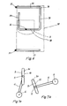
- FIG. 7 In which a flat-shaped backrest body 3a is rotatably attached to the corresponding swivel arm 4.
- One outer surface 9 serves to lean the back (FIG. 7a), while in the lower leg support position (FIG. 7b) the opposite outer surface 10 faces the lower legs.
- a holding arm 11 which projects to the side of the seat 2 and to which the backrest body 3 is fastened.
- the backrest body 3 is simply plugged onto the holding arm 11.
- From the backrest body 3 facing away from the swivel arm 4 is a protruding toward the seat, to the swivel axis 6 coaxial bearing arm 12, which is in a rotatable plug-in connection with a rigidly arranged bearing part 14 on the seat or on the seat frame 13, advantageously below the seat.
- the swivel arm 4, the holding arm 11 and the bearing arm 12 can be formed in a simple and elegant manner simply by a U-shaped swivel bracket 15, which can be bent in one piece from rod material.
- the crossbar of the U forms the swivel arm 4, while the holding arm 11 and the bearing arm 12 are each formed by one of the two U-legs.
- the seat 2 and the backrest body 3 lie freely opposite one another, so that the person's entry from this side is not impeded when the backrest body 3 is in the shin rest position (FIG. 3).
- the backrest body 3 can be freely pivoted by means of the swivel bracket 15, the swivel movement being limited at both ends by a stop. Between these two stops, the backrest body or the swivel bracket can be pivoted back and forth as desired, one stop in the backrest position and the other stop in the lower leg rest position preventing a secure hold against further pivoting beyond the respective position.
- a stop arrangement Lich Various designs are possible for such a stop arrangement Lich.
- a particularly expedient embodiment is realized, which also has the advantage that it is possible to provide different pairs of stops practically without additional effort, each of which is assigned a different pivot angle.
- the correct position of the backrest body 3 in the backrest position and in the lower leg position depends on the body size. It would be most advantageous if the backrest position and the lower leg rest position could be adjusted independently of one another. However, this would increase the operational effort and the manufacturing costs. In addition, it has been found in practice that there is a characteristic backrest position and a characteristic lower leg position for certain body size ranges, so that, as already mentioned, the swiveling angle can be changed by providing several pairs of stops which can be used and which are each assigned a different swivel angle are sufficient.
- the bearing part which is arranged rigidly on the seat frame 13, and the bearing arm 12 carry plates 16, 17 which abut one another (in FIG. 5 they are drawn apart from one another so that their structure can be recognized), one plate 16 of which has a plurality of circular-arcuate recesses 18, 19, 20, the number of which corresponds to the number of desired stop pairs.
- Each arcuate recess 18 or 19 or 20 forms with its ends a pair of stops 18a, 18b or 19a, 19b or 20a, 20b.
- the other plate 17 has an equal number of fastening points 21, 22, 23, in the exemplary embodiment threaded bores, which can optionally be used for a stop body 24 engaging in the respective recess 18, 19 or 20.
- each attachment point 21, 22 and 23 is assigned to one of the circular arc-shaped recesses 18, 19 and 20, so that each attachment point is opposite a recess.
- the radius of the arcuate recesses and the distribution of the recesses seen over the circumference play no role, so that they can be arranged in the most space-efficient way.
- the length of the arcuate recesses is essential because it determines the respective pivot angle of the backrest body 3.
- the fastening points 21, 22, 23 are arranged so distributed over the plate 17 that both the backrest position and the lower leg position of the backrest body 3 in the desired pivot angle determined by the length of the associated arcuate recess Angular position. If you put the on Impact body 24, for example, in the bore 21, the stop body 24 engages in the arcuate recess 18 of the plate 16 (it has already been pointed out that the plate 6 lies flat against the plate 17 in the assembled state), wherein it is in the recess end 18b located. The backrest body 3 then assumes its upper end position in this arrangement. When pivoting the backrest body downward, the stop body 24 passes through the recess 18 until it strikes the opposite recess end 18a.
- the bearing part 14 is a bearing sleeve penetrated by the bearing arm 12, on the end of which facing away from the pivot arm 4 is the plate 17 which has the fastening points 21, 22, 23.
- the plate 16 having the recesses 18, 19, 20 is located at the inserted end of the bearing arm 12, which emerges at the end of the bearing sleeve 14 opposite the pivot arm 4.
- the arrangement could also be reversed, namely that the plate seated on the bearing part 14 carries the arcuate recesses and the plate arranged on the bearing arm 12 carries the attachment points for the stop body.
- the illustrated embodiment is advantageous.
- the annular recesses 18, 19, 20 Bag recesses In order to obtain a closed visible surface on the plate 16 on the outside facing away from the other plate 17, the annular recesses 18, 19, 20 Bag recesses.
- the recesses can also be formed continuously and a cover plate or the like can be placed on the outside of the plate 16.
- a clamping screw 25 can be provided, for example, which is screwed into the bearing part 14 from the outside and is firmly clamped against the bearing arm 12.
- the bearing part 14 can be fixed directly or, as in the exemplary embodiment, rigidly to the seat frame 13 via the plate 17.
- the plate 17 is welded to the seat frame.
- the height of the seat 2 can be adjusted.
- the seat is supported in the exemplary embodiment by a post-like foot, which has two telescoping interlocking post parts 26, 27, of which the upper post part 27 can be fixed in the respective height, for example by means of a retaining bolt 28 which passes through the upper post part 27 into a Holding hole one on the lower post part 26 in front seen row of holes 29 engages.
- the post-like foot - even if it is not adjustable in height - has the advantage that the seat device is free of feet, especially in the front area, so that the legs of the seated person are not hindered.
- the already described bearing part 14 is arranged on the upper post part 27 so that it follows the height adjustment of the seat.
- the seat 2 is arranged so that it can be tilted forward, which is particularly important for sitting in the lower leg support position, since one should sit here as obliquely as possible (see FIG. 3).
- the seat can be tilted forward against the force of a spring, not shown, so that the seat 2 automatically returns to its starting position (FIG. 2), in which it can also be inclined, but only by a small angular amount.
- the seat device 1 is connected to the table 2 des only on one side of the seat 2, specifically on the side of the swivel arm 4, and can be swiveled into a position below the table top 30.
- the table frame has legs 31, 32 arranged in the region of the two longitudinal ends of the table, which leave the table side facing the seat 2, with a floor brace 33 and 34 resting on the floor and facing the seat 2, with at least one of the two Table floor struts, in the practical embodiment only to the table floor strut 34, one is also attached to the floor strut 35 of the seat frame 13 lying on the floor.
- the two pillars 31, 32 together with the respectively assigned floor strut 33 and 34 form an L-shape, which is particularly advantageous because in this way the entry of the person between the table and the seat is not hindered.
- the pivoting of the seat device 1 into the space below the table top 30 can take place without hindrance.
- the table floor strut 34 is connected to the seat frame floor strut 35. Between these two struts there is an articulation 36 with a vertical articulation axis, which enables the seat device to be pivoted horizontally under the table top 30.
- the other table floor strut 33 is arranged at a distance from the seat frame 13.
- the seat frame 13 has a floor frame 37 lying on the floor with an essentially U-shaped shape open towards the table 2 Tisch.
- the post-like foot 26, 27 supporting the seat 2 stands high from the frame crosspiece 38, ie from the crosspiece of the U.
- One of the frame legs, ie a U-leg forms the seat frame floor strut 35 and, as already mentioned, is articulated to the facing table floor strut e 34.
- the frame crossbar 38 is shorter than the distance between the two table base struts 33, 34, which favors the pivoting of the seat device under the table top.
- the bottom frame 37 of the frame is bent from a suitably hollow rod material.
- the two legs 31, 32 at the upper end opposite the floor struts 33, 34 can advantageously be integrally connected to one another via a cross member 40, so that the two table -Floor struts 33, 34, the legs 31, 32 and the cross member 40 can be formed by a one-piece tube bent part.
- the cross member 40 runs above the table top 30.
- the table frame shown has castors 41, 42, which are each arranged and mounted at the facing longitudinal end of the table at the bottom at the transition between the supporting leg 31 or 32 and the table floor strut 33 or 34. In the position of use of the table shown in FIG. 1, the castors do not project downwards over the table floor struts 33, 34, so that the table stands securely. If, on the other hand, the table and thus the folded unit is tilted in the direction away from the seat when the seat device is pivoted under the table top 30, the castors 41, 42 become effective because they protrude beyond the table frame on the side facing away from the seat. You can then move the entire unit and move it to another room, for example.
- the traverse 40 projecting upward above the table top can serve as a handle for tilting and moving.
- the free ends of the two support arms 43 can advantageously be integrally connected to one another via a connecting rod 44 running parallel to the table edge.
- the connecting rod 44 forms a U-shaped support frame for the table top 30 with the two support arms 43.
- the table top 30 is adjustable in height so that it can be adapted to the size of the user.
- this is achieved in that the legs 31, 32 each have a row of holes 45, to the holes of which the respective support arm 43 can be attached.
- the support arms 43 can have an attachment extension 46 which is angled parallel to the associated supporting leg. This can carry a plug-in projection 47 and, in the single and multiple grid spacing of the row of holes 45, have a fastening bore through which a threaded bolt which also engages in a hole in the row of holes 45 is inserted.
- the table top 30 can be inclined toward the seat 2. This measure, known per se, is particularly important with regard to the seating position according to FIG. 3, in which the backrest body 3 forms the lower leg system. When the table top 30 is inclined, it is more convenient to work or play on it.
- the connecting rod 44 can be used for pivoting the table top 30.
- a fitting indicated at 48 holds the table top 30 in the inclined position.
- the table floor strut 34 and the seat frame floor strut 35 are arranged in alignment with one another. If the seat device 1 is pivoted by means of the joint 36, the position of the seat device below the table top as shown in FIG. 6 results.
- the swivel angle is about 90 °.
- the table floor struts 33, 34 are longer than the seat frame 13 is wide, so that the space under the table top is sufficient.
- the seat device 1 can be pivoted a little outwards against the pivoting direction by means of the joint 36, as a result of which the distance between the table and the seat on the entry side increases.
- table 2 ⁇ and the seat device 1 are connected to each other with a variable distance. This can also be conducive to a favorable working position.
- This variant is not shown in the drawing. However, it is easy to imagine, since for this purpose, for example, only the table floor strut 34 would have to be formed in two parts in the manner of a telescope.
Landscapes
- Chairs For Special Purposes, Such As Reclining Chairs (AREA)
- Chairs Characterized By Structure (AREA)
- Special Chairs (AREA)
Applications Claiming Priority (2)
| Application Number | Priority Date | Filing Date | Title |
|---|---|---|---|
| DE3623224 | 1986-07-10 | ||
| DE19863623224 DE3623224A1 (de) | 1986-07-10 | 1986-07-10 | Stuhlartige sitzvorrichtung |
Publications (2)
| Publication Number | Publication Date |
|---|---|
| EP0252274A2 true EP0252274A2 (fr) | 1988-01-13 |
| EP0252274A3 EP0252274A3 (fr) | 1988-05-25 |
Family
ID=6304845
Family Applications (1)
| Application Number | Title | Priority Date | Filing Date |
|---|---|---|---|
| EP87107864A Withdrawn EP0252274A3 (fr) | 1986-07-10 | 1987-05-30 | Dispositif pour s'asseoir en forme de chaise |
Country Status (3)
| Country | Link |
|---|---|
| EP (1) | EP0252274A3 (fr) |
| JP (1) | JPS6399809A (fr) |
| DE (1) | DE3623224A1 (fr) |
Cited By (15)
| Publication number | Priority date | Publication date | Assignee | Title |
|---|---|---|---|---|
| GB2202138A (en) * | 1987-03-20 | 1988-09-21 | Andrew Magnar Kvalheim | Multi-position convertible therapeutic chair |
| EP0473291A1 (fr) * | 1990-08-27 | 1992-03-04 | Andrew M. Kvalheim | Chaise transformable |
| EP0476057A1 (fr) * | 1989-06-16 | 1992-03-25 | Workstation Environments Inc | Systeme pour postes de travail. |
| WO1993009701A1 (fr) * | 1991-11-11 | 1993-05-27 | Josef Huser | Siege convertible |
| FR2689737A1 (fr) * | 1992-04-13 | 1993-10-15 | Baldo Emmanuel | Ensemble mobilier bureau siège multiréglable et séparable. |
| WO1995034457A1 (fr) * | 1994-06-15 | 1995-12-21 | Städet I Bergsjöbygden Ab | Appareil reglable formant dossier pour engins a usage sportif et de competition |
| DE4435023A1 (de) * | 1994-09-25 | 1996-03-28 | Frithjof Kremeike | Sitzgelegenheit mit Rückenlehne, dadurch gekennzeichnet, daß man sie von hinten besteigen kann |
| DE19543818C1 (de) * | 1995-11-24 | 1997-05-07 | Desanta | Stuhl mit Kniestütze |
| CH689578A5 (de) * | 1995-10-25 | 1999-06-30 | Huser Thomas | EDV-Büromöbel. |
| EP0980658A1 (fr) * | 1998-08-17 | 2000-02-23 | Beatrice Kern | Pupitre de lecture adapté pour ordinateur et procédé permettant d'obtenir une position de travail ergonomique |
| WO2005060795A2 (fr) * | 2003-12-22 | 2005-07-07 | Garderobia Metallwaren Gmbh | Ensemble siege |
| US7497515B2 (en) * | 2000-03-23 | 2009-03-03 | Jonathan Krehm, legal representative | Ergonomic chair |
| US7571959B2 (en) * | 2004-03-26 | 2009-08-11 | Krueger International, Inc. | Student desk |
| US7887136B2 (en) * | 2007-08-16 | 2011-02-15 | Stefan Zoell | Device for supporting a human body in various positions |
| US11051627B2 (en) * | 2016-12-05 | 2021-07-06 | Mobiiuz | Anterior support device for the lower limbs |
Families Citing this family (5)
| Publication number | Priority date | Publication date | Assignee | Title |
|---|---|---|---|---|
| AT394134B (de) * | 1990-04-05 | 1992-02-10 | Sifa Sitzfabrik Gmbh | Sessel |
| DE4015841A1 (de) * | 1990-05-17 | 1991-11-21 | Hans Prof Roericht | Mehrzweckstuhl |
| DE4143538C2 (de) * | 1991-02-22 | 1995-07-13 | Georg Engel | Verwandlungssitz zur wahlweisen Benutzung als Stuhl mit Armlehnen oder als Kniesitz |
| DE4234883C1 (de) * | 1992-10-16 | 1994-04-21 | Pius Ponticelli | Stuhl |
| JP6104883B2 (ja) * | 2012-03-15 | 2017-03-29 | 株式会社亘陽 | チェアベッド |
Citations (3)
| Publication number | Priority date | Publication date | Assignee | Title |
|---|---|---|---|---|
| US3837705A (en) * | 1972-01-31 | 1974-09-24 | Olivetti & Co Spa | Office chair |
| WO1985000275A1 (fr) * | 1983-07-08 | 1985-01-31 | Mengshoel Hans Chr | Siege et son utilisation |
| EP0179748A2 (fr) * | 1984-10-17 | 1986-04-30 | Liedberg / Östlund AB | Chaise de travail |
-
1986
- 1986-07-10 DE DE19863623224 patent/DE3623224A1/de not_active Withdrawn
-
1987
- 1987-05-30 EP EP87107864A patent/EP0252274A3/fr not_active Withdrawn
- 1987-06-29 JP JP62162202A patent/JPS6399809A/ja active Pending
Patent Citations (3)
| Publication number | Priority date | Publication date | Assignee | Title |
|---|---|---|---|---|
| US3837705A (en) * | 1972-01-31 | 1974-09-24 | Olivetti & Co Spa | Office chair |
| WO1985000275A1 (fr) * | 1983-07-08 | 1985-01-31 | Mengshoel Hans Chr | Siege et son utilisation |
| EP0179748A2 (fr) * | 1984-10-17 | 1986-04-30 | Liedberg / Östlund AB | Chaise de travail |
Cited By (20)
| Publication number | Priority date | Publication date | Assignee | Title |
|---|---|---|---|---|
| GB2202138A (en) * | 1987-03-20 | 1988-09-21 | Andrew Magnar Kvalheim | Multi-position convertible therapeutic chair |
| GB2202138B (en) * | 1987-03-20 | 1990-10-17 | Andrew Magnar Kvalheim | Multi-position convertible therapeutic chair |
| EP0476057A1 (fr) * | 1989-06-16 | 1992-03-25 | Workstation Environments Inc | Systeme pour postes de travail. |
| EP0476057A4 (en) * | 1989-06-16 | 1993-03-03 | Workstation Environments, Inc | Work station system |
| EP0473291A1 (fr) * | 1990-08-27 | 1992-03-04 | Andrew M. Kvalheim | Chaise transformable |
| WO1993009701A1 (fr) * | 1991-11-11 | 1993-05-27 | Josef Huser | Siege convertible |
| FR2689737A1 (fr) * | 1992-04-13 | 1993-10-15 | Baldo Emmanuel | Ensemble mobilier bureau siège multiréglable et séparable. |
| WO1995034457A1 (fr) * | 1994-06-15 | 1995-12-21 | Städet I Bergsjöbygden Ab | Appareil reglable formant dossier pour engins a usage sportif et de competition |
| DE4435023A1 (de) * | 1994-09-25 | 1996-03-28 | Frithjof Kremeike | Sitzgelegenheit mit Rückenlehne, dadurch gekennzeichnet, daß man sie von hinten besteigen kann |
| CH689578A5 (de) * | 1995-10-25 | 1999-06-30 | Huser Thomas | EDV-Büromöbel. |
| EP0775458A1 (fr) * | 1995-11-24 | 1997-05-28 | Simon Desanta | Siège avec surface d'appui des genoux |
| US5782534A (en) * | 1995-11-24 | 1998-07-21 | Desanta; Simon | Chair with knee support |
| DE19543818C1 (de) * | 1995-11-24 | 1997-05-07 | Desanta | Stuhl mit Kniestütze |
| EP0980658A1 (fr) * | 1998-08-17 | 2000-02-23 | Beatrice Kern | Pupitre de lecture adapté pour ordinateur et procédé permettant d'obtenir une position de travail ergonomique |
| US7497515B2 (en) * | 2000-03-23 | 2009-03-03 | Jonathan Krehm, legal representative | Ergonomic chair |
| WO2005060795A2 (fr) * | 2003-12-22 | 2005-07-07 | Garderobia Metallwaren Gmbh | Ensemble siege |
| WO2005060795A3 (fr) * | 2003-12-22 | 2005-08-25 | Garderobia Metallwaren Gmbh | Ensemble siege |
| US7571959B2 (en) * | 2004-03-26 | 2009-08-11 | Krueger International, Inc. | Student desk |
| US7887136B2 (en) * | 2007-08-16 | 2011-02-15 | Stefan Zoell | Device for supporting a human body in various positions |
| US11051627B2 (en) * | 2016-12-05 | 2021-07-06 | Mobiiuz | Anterior support device for the lower limbs |
Also Published As
| Publication number | Publication date |
|---|---|
| EP0252274A3 (fr) | 1988-05-25 |
| JPS6399809A (ja) | 1988-05-02 |
| DE3623224A1 (de) | 1988-01-21 |
Similar Documents
| Publication | Publication Date | Title |
|---|---|---|
| EP0252274A2 (fr) | Dispositif pour s'asseoir en forme de chaise | |
| EP0635227B1 (fr) | Chaise, notamment chaise de bureau | |
| DE60300064T2 (de) | Stuhl mit beweglichem Sitz und Rückenlehne | |
| DE2223886C3 (de) | Stuhl mit durch einen Hebel zu betätigender Höhen- und RückenlehnenversteUung | |
| EP0058411A1 (fr) | Fauteuil gynécologique d'examen et d'accouchement | |
| DE2304195B2 (de) | Vorrichtung zum tragen von koerperbehinderten personen | |
| EP0198957A2 (fr) | Chaise roulante pour invalides | |
| DE60022752T2 (de) | Rollstuhl | |
| EP0517006B1 (fr) | Support pour une personne en position debout | |
| DE2736550C2 (fr) | ||
| EP0114600A2 (fr) | Chaise, notamment chaise de bureau | |
| EP0510348A1 (fr) | Chaise, notamment chaise de bureau | |
| DE3612451A1 (de) | Fahrbare vorrichtung zur handhabung kranker oder behinderter personen | |
| WO2002065971A1 (fr) | Coque de siege comprenant des elements de soutien reglables | |
| DE1404660C3 (de) | Verstellsessel | |
| EP1707076A2 (fr) | Piece de meuble combinant une table et un siège | |
| DE8312140U1 (de) | Stehentlastung | |
| DE2837558A1 (de) | Arbeitsstuhl | |
| DE1580621A1 (de) | Sitz,insbesondere fuer Kraftfahrzeuge | |
| DE851405C (de) | Zusammenklappbares Moebelstueck, bestehend aus einem Tisch und um diesen herum angeordneten, unter die Tischplatte klappbaren Stuehlen | |
| DE2954540C2 (fr) | ||
| DE10229436A1 (de) | Kinderstuhl mit einer höhenverstellbaren Sitz- und/oder Fußfläche sowie einem Möbelbeschlag hierfür | |
| DE4103313A1 (de) | Hochstuhl | |
| DE19533069A1 (de) | Stuhl | |
| CH473579A (de) | Fahrbarer Stuhl mit Fuss- und Armstützen |
Legal Events
| Date | Code | Title | Description |
|---|---|---|---|
| PUAI | Public reference made under article 153(3) epc to a published international application that has entered the european phase |
Free format text: ORIGINAL CODE: 0009012 |
|
| AK | Designated contracting states |
Kind code of ref document: A2 Designated state(s): AT BE CH DE ES FR GB GR IT LI LU NL SE |
|
| PUAL | Search report despatched |
Free format text: ORIGINAL CODE: 0009013 |
|
| AK | Designated contracting states |
Kind code of ref document: A3 Designated state(s): AT BE CH DE ES FR GB GR IT LI LU NL SE |
|
| STAA | Information on the status of an ep patent application or granted ep patent |
Free format text: STATUS: THE APPLICATION IS DEEMED TO BE WITHDRAWN |
|
| 18D | Application deemed to be withdrawn |
Effective date: 19890408 |
|
| RIN1 | Information on inventor provided before grant (corrected) |
Inventor name: MOLL, HELLMUTH Inventor name: MOLL, REINER |